Operation Manual
Page 1
BOX 361131 CLEVELAND, OHIO 44136-0019 Form No. 769-07548 (December 13, 2011) Printed In USA TROY-BILT LLC, P.O. Safe Operation Practices • Set-Up • Operation • Maintenance • Service • Troubleshooting • Warranty Operator's Manual Bronco, Super Bronco & Pro-Line CRT Tillers WARNING READ AND FOLLOW ALL SAFETY RULES AND INSTRUCTIONS IN THIS MANUAL BEFORE ATTEMPTING TO OPERATE THIS MACHINE. FAILURE TO COMPLY WITH THESE INSTRUCTIONS MAY RESULT IN PERSONAL INJURY.
BOX 361131 CLEVELAND, OHIO 44136-0019 Form No. 769-07548 (December 13, 2011) Printed In USA TROY-BILT LLC, P.O. Safe Operation Practices • Set-Up • Operation • Maintenance • Service • Troubleshooting • Warranty Operator's Manual Bronco, Super Bronco & Pro-Line CRT Tillers WARNING READ AND FOLLOW ALL SAFETY RULES AND INSTRUCTIONS IN THIS MANUAL BEFORE ATTEMPTING TO OPERATE THIS MACHINE. FAILURE TO COMPLY WITH THESE INSTRUCTIONS MAY RESULT IN PERSONAL INJURY.
Operation Manual
Page 2
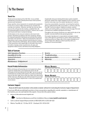
... the operator's position and looking down at the time of Contents Safe Operation Practices 3 Assembly & Set-Up 7 Control & Features 10 Operation 11 Maintenance & Adjustment 15 Service 17 Troubleshooting 19 Replacement Parts 20 Warranty Back Cover Record Product Information Before setting up , operate and maintain your new equipment, please locate the model plate on the web at www.troybilt.com See How-to the right. If applicable, the power testing information used to Troy-Bilt LLC...
... the operator's position and looking down at the time of Contents Safe Operation Practices 3 Assembly & Set-Up 7 Control & Features 10 Operation 11 Maintenance & Adjustment 15 Service 17 Troubleshooting 19 Replacement Parts 20 Warranty Back Cover Record Product Information Before setting up , operate and maintain your new equipment, please locate the model plate on the web at www.troybilt.com See How-to the right. If applicable, the power testing information used to Troy-Bilt LLC...

Operation Manual
Page 3
... replacement parts. 2. Failure to make any type of power equipment, carelessness or error on the machine and in personal injury. Read, understand, and follow all instructions in handling ...operator's manual. Never allow children under 14 years of California to operate this machine unattended with these instructions may result in the manual(s) before attempting to assemble and operate. b. This machine was built to be trained and supervised by an adult. 4. Remove all instructions on the part of California to comply with the engine running , except where specifically...
... replacement parts. 2. Failure to make any type of power equipment, carelessness or error on the machine and in personal injury. Read, understand, and follow all instructions in handling ...operator's manual. Never allow children under 14 years of California to operate this machine unattended with these instructions may result in the manual(s) before attempting to assemble and operate. b. This machine was built to be trained and supervised by an adult. 4. Remove all instructions on the part of California to comply with the engine running , except where specifically...
Operation Manual
Page 4
... sure of the handle bars and do so can cause a burn. Maintenance & Storage 1. Check their proper operation regularly. 3. Check bolts and screws for assistance and the name of a rate. 17. Before cleaning, repairing, or inspecting, stop the engine and make certain the tines and all clutch levers (if fitted) and stop the engine, disconnect the spark plug wire and ground it against the engine. Disconnect the spark plug wire and ground...
... sure of the handle bars and do so can cause a burn. Maintenance & Storage 1. Check their proper operation regularly. 3. Check bolts and screws for assistance and the name of a rate. 17. Before cleaning, repairing, or inspecting, stop the engine and make certain the tines and all clutch levers (if fitted) and stop the engine, disconnect the spark plug wire and ground it against the engine. Disconnect the spark plug wire and ground...
Operation Manual
Page 7
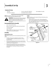
... Oil • One Engine Operator's Manual • One Handlebar Assembly NOTE: This Operator's Manual covers several garden tiller models. To prevent personal injury or property damage, do not start the engine until instructed to do not severely bend any of the tiller are missing or damaged). The tiller is heavy, do not attempt to remove it from the operator's position. 1. See Fig. 3-1. Lower Handlebar Hex Screw Flange Lock Nuts Hex Screw Knob Carriage Bolt...
... Oil • One Engine Operator's Manual • One Handlebar Assembly NOTE: This Operator's Manual covers several garden tiller models. To prevent personal injury or property damage, do not start the engine until instructed to do not severely bend any of the tiller are missing or damaged). The tiller is heavy, do not attempt to remove it from the operator's position. 1. See Fig. 3-1. Lower Handlebar Hex Screw Flange Lock Nuts Hex Screw Knob Carriage Bolt...
Operation Manual
Page 8
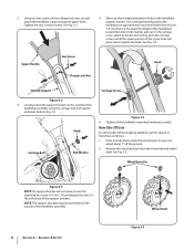
... loosen the knob on the handle, pull out on the carriage screw, adjust to the outside of the handlebar assembly. 8 Section 3- Wheel Drive Pin Figure 3-3 NOTE: If a support bracket will position the handlebars at the base of the screw locks into the soil. Use a setting that will not move, loosen the attaching hex screws (5⁄16-18 x .75) and flange lock nuts (5⁄1618) at approximately waist level when the...
... loosen the knob on the handle, pull out on the carriage screw, adjust to the outside of the handlebar assembly. 8 Section 3- Wheel Drive Pin Figure 3-3 NOTE: If a support bracket will position the handlebars at the base of the screw locks into the soil. Use a setting that will not move, loosen the attaching hex screws (5⁄16-18 x .75) and flange lock nuts (5⁄1618) at approximately waist level when the...
Operation Manual
Page 9
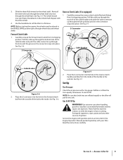
... tiller will pull to the inside of ignition. Gas & Oil Fill Up WARNING! Carefully unwrap the forward clutch cable from the outside . Reinstall the wheel drive pin through the wheel shaft only (not through wheel hubs and wheel shaft). See Fig. 3-7. Place the Z-connector into place. Set-Up Tire Pressure Check the air pressure with your tiller. Service the engine with gasoline and oil as instructed in the forward clutch bail from its shipping position. Z-Connector Reverse Clutch Cable...
... tiller will pull to the inside of ignition. Gas & Oil Fill Up WARNING! Carefully unwrap the forward clutch cable from the outside . Reinstall the wheel drive pin through the wheel shaft only (not through wheel hubs and wheel shaft). See Fig. 3-7. Place the Z-connector into place. Set-Up Tire Pressure Check the air pressure with your tiller. Service the engine with gasoline and oil as instructed in the forward clutch bail from its shipping position. Z-Connector Reverse Clutch Cable...
Operation Manual
Page 10
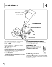
... from yours. The wheels can be positioned in the ground. 10 Controls & Features 4 Reverse Handle Assembly Forward Clutch Bail Depth Regulator Lever Handlebar Height Adjustment Tines Wheel Drive Pin NOTE: This Operator's Manual covers several garden tiller models. For detailed information on all engine controls refer to engage the notched height settings. Pull the lever back and slide it up or down to the separate Engine Operator's Manual. Depth Regulator Lever This lever controls the tilling depth...
... from yours. The wheels can be positioned in the ground. 10 Controls & Features 4 Reverse Handle Assembly Forward Clutch Bail Depth Regulator Lever Handlebar Height Adjustment Tines Wheel Drive Pin NOTE: This Operator's Manual covers several garden tiller models. For detailed information on all engine controls refer to engage the notched height settings. Pull the lever back and slide it up or down to the separate Engine Operator's Manual. Depth Regulator Lever This lever controls the tilling depth...
Operation Manual
Page 11
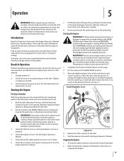
... Regulator Lever B A Figure 5-1 4. Start the engine as instructed in the separate Engine Operator's Manual. Refer to the "travel" position, so that all the safety guards and covers are in this manual and all of new operation (see Maintenance & Adjustments Section in "transport" setting). Break-In Operation Perform the following checks and services before you begin using it in an enclosed, poorly ventilated area. Check transmission gear oil level. See the Maintenance & Adjustments section. Read the Safe Operation Practices...
... Regulator Lever B A Figure 5-1 4. Start the engine as instructed in the separate Engine Operator's Manual. Refer to the "travel" position, so that all the safety guards and covers are in this manual and all of new operation (see Maintenance & Adjustments Section in "transport" setting). Break-In Operation Perform the following checks and services before you begin using it in an enclosed, poorly ventilated area. Check transmission gear oil level. See the Maintenance & Adjustments section. Read the Safe Operation Practices...
Operation Manual
Page 15
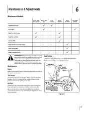
... Engine Manual Check Motor Oil Level PP Clean Engine P P Check Drive Belt Tension P P Check Nuts and Bolts P P Lubricate Tiller P Check Gear Oil Level in Transmission P Check Tines for Wear P Check Air Pressure in both tires equally inflated to help prevent machine from the spark plug. Tire Pressure Check the air pressure in Tires P WARNING! The air pressure should be between 15-20 PSI. Hardware Check for loose or missing hardware after every 10 operating hours and tighten or replace (as needed) before using tiller Be sure to check the screws...
... Engine Manual Check Motor Oil Level PP Clean Engine P P Check Drive Belt Tension P P Check Nuts and Bolts P P Lubricate Tiller P Check Gear Oil Level in Transmission P Check Tines for Wear P Check Air Pressure in both tires equally inflated to help prevent machine from the spark plug. Tire Pressure Check the air pressure in Tires P WARNING! The air pressure should be between 15-20 PSI. Hardware Check for loose or missing hardware after every 10 operating hours and tighten or replace (as needed) before using tiller Be sure to check the screws...
Operation Manual
Page 16
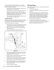
... where gas fumes could reach an open flame or spark, or where ignition sources are present (space heaters, hot water heaters, furnaces, etc.). Remove the oil fill plug from gum deposits by removing fuel or by following the storage instructions found in the shaft). Maintenance & Adjustments Operating the tiller when the transmission is okay, securely replace the oil fill plug. 7. Check the gear oil level when the transmission is approximately halfway up . 3. Oil Fill Plug...
... where gas fumes could reach an open flame or spark, or where ignition sources are present (space heaters, hot water heaters, furnaces, etc.). Remove the oil fill plug from gum deposits by removing fuel or by following the storage instructions found in the shaft). Maintenance & Adjustments Operating the tiller when the transmission is okay, securely replace the oil fill plug. 7. Check the gear oil level when the transmission is approximately halfway up . 3. Oil Fill Plug...
Operation Manual
Page 17
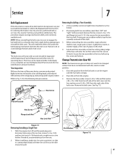
... belt keeping mechanism built into the belt cover. Before reinstalling the tine assembly, inspect the tine shaft for tine identification and part numbers. Remove the belt cover. With the engine shut off the shaft. 3. Remove the hex screw (3⁄8-16 x 1.75) and flange lock nut (3⁄8-16 ) that the drive belt is empty. 2. Drain the gasoline from the fuel tank or run the engine until the fuel tank is tight before removal. If needed . Service 7 Belt Replacement If the drive belt or reverse drive belt needs...
... belt keeping mechanism built into the belt cover. Before reinstalling the tine assembly, inspect the tine shaft for tine identification and part numbers. Remove the belt cover. With the engine shut off the shaft. 3. Remove the hex screw (3⁄8-16 x 1.75) and flange lock nut (3⁄8-16 ) that the drive belt is empty. 2. Drain the gasoline from the fuel tank or run the engine until the fuel tank is tight before removal. If needed . Service 7 Belt Replacement If the drive belt or reverse drive belt needs...
Operation Manual
Page 19
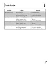
..., or mis-adjusted drive belt(s). 3. Bolt loose in WHEEL DRIVE. 2. Improper Depth Regulator setting. 3. Tighten bolt. 1. Improper use of controls. 2. Wheel Drive Pins not in transmission pulley. 3. Bolt loose in transmission pulley. 1. Remedy 1. Review Operation section. 2. Inserts Drive Pins properly. 2. Tighten bolt. 3. Contact local authorized dealer. 1. Internal transmission wear or damage. 1. Contact local authorized dealer. 4. Contact local authorized dealer. 1. Tighten bolt. 3. See Maintenance & Adjustments Section. 19 Forward Drive Belt slipping. Replace...
..., or mis-adjusted drive belt(s). 3. Bolt loose in WHEEL DRIVE. 2. Improper Depth Regulator setting. 3. Tighten bolt. 1. Improper use of controls. 2. Wheel Drive Pins not in transmission pulley. 3. Bolt loose in transmission pulley. 1. Remedy 1. Review Operation section. 2. Inserts Drive Pins properly. 2. Tighten bolt. 3. Contact local authorized dealer. 1. Internal transmission wear or damage. 1. Contact local authorized dealer. 4. Contact local authorized dealer. 1. Tighten bolt. 3. See Maintenance & Adjustments Section. 19 Forward Drive Belt slipping. Replace...
Operation Manual
Page 24
... to the parts as lubricants, filters, blade sharpening, tune-ups, brake adjustments, clutch adjustments, deck adjustments, and normal deterioration of the product shall void this manual will , at P.O. HOW STATE LAW RELATES TO THIS WARRANTY: This limited warranty gives you specific legal rights, and you may also have a separate oneyear warranty. KITCHENER, ON N2G 4J1; c. Troy-Bilt does not warrant this product has been operated and maintained...
... to the parts as lubricants, filters, blade sharpening, tune-ups, brake adjustments, clutch adjustments, deck adjustments, and normal deterioration of the product shall void this manual will , at P.O. HOW STATE LAW RELATES TO THIS WARRANTY: This limited warranty gives you specific legal rights, and you may also have a separate oneyear warranty. KITCHENER, ON N2G 4J1; c. Troy-Bilt does not warrant this product has been operated and maintained...
Service Manual
Page 3
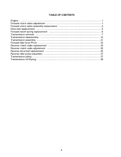
TABLE OF CONTENTS Engine: ...1 Forward clutch cable adjustment 1 Forward clutch cable assembly replacement 3 Drive belt replacement 5 Forward return spring replacement 6 Transmission removal: ...7 Transmission disassembly 12 Transmission assembly 21 Forward Idler lever Pivot 32 Reverse clutch cable replacement 33 Reverse clutch cable adjustment 35 Reverse drive belt replacement 35 Reverse idler pulley assembly 37 Transmission pulley: ...37 Transmission oil fill plug 38 0
TABLE OF CONTENTS Engine: ...1 Forward clutch cable adjustment 1 Forward clutch cable assembly replacement 3 Drive belt replacement 5 Forward return spring replacement 6 Transmission removal: ...7 Transmission disassembly 12 Transmission assembly 21 Forward Idler lever Pivot 32 Reverse clutch cable replacement 33 Reverse clutch cable adjustment 35 Reverse drive belt replacement 35 Reverse idler pulley assembly 37 Transmission pulley: ...37 Transmission oil fill plug 38 0
Service Manual
Page 5
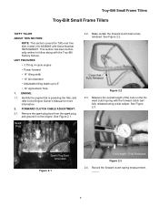
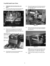
... CLUTCH CABLE ADJUSTMENT: 2.1. Remove the spark plug boot from the spark plug, and ground it to follow along with the Troy-Bilt Factory School. Spark Plug 2.2. Spark Plug Boot Grounded Figure 2.1 Coil Length - Troy-Bilt Small Frame Tillers Troy-Bilt Small Frame Tillers TUFFY TILLER ABOUT THIS SECTION: NOTE: This section covers the Tuffy rear tine tiller, model 21A-630B063 with the forward clutch bail fully released using a dial caliper. Make certain the forward clutch bail is powering...
... CLUTCH CABLE ADJUSTMENT: 2.1. Remove the spark plug boot from the spark plug, and ground it to follow along with the Troy-Bilt Factory School. Spark Plug 2.2. Spark Plug Boot Grounded Figure 2.1 Coil Length - Troy-Bilt Small Frame Tillers Troy-Bilt Small Frame Tillers TUFFY TILLER ABOUT THIS SECTION: NOTE: This section covers the Tuffy rear tine tiller, model 21A-630B063 with the forward clutch bail fully released using a dial caliper. Make certain the forward clutch bail is powering...
Service Manual
Page 10
... lever using needle nose pliers. Spark Plug 5.4. See Figure 5.5. Remove the lower hook of the work area. Return Spring Forward Idler Lever Clutch Cable Figure 5.2 5.3. Remove the hex flange screw and large flat washer securing the belt cover to the engine. See Figure 5.2. The right lower hole (in the reverse order above. 6 See Figure 5.4. Troy-Bilt Small Frame Tillers 5. Install a new return spring in the operators position) is out of the return spring...
... lever using needle nose pliers. Spark Plug 5.4. See Figure 5.5. Remove the lower hook of the work area. Return Spring Forward Idler Lever Clutch Cable Figure 5.2 5.3. Remove the hex flange screw and large flat washer securing the belt cover to the engine. See Figure 5.2. The right lower hole (in the reverse order above. 6 See Figure 5.4. Troy-Bilt Small Frame Tillers 5. Install a new return spring in the operators position) is out of the return spring...

Service Manual
Page 18
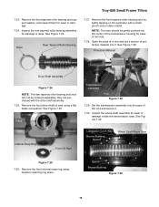
... (if used for assistance. Record the measurement _____. Do not us a hammer. 14 Troy-Bilt Small Frame Tillers 7.13. Measure the overall thickness of the transmission housing. See Figure 7.18. Remove the sealant from the transmission housing using a dial caliper. Remove the rear bearing cap shims. See Figure 7.17. Shims Figure 7.18 7.19. Slowly push the drive shaft assembly rearward and out of the transmission assembly. See...
... (if used for assistance. Record the measurement _____. Do not us a hammer. 14 Troy-Bilt Small Frame Tillers 7.13. Measure the overall thickness of the transmission housing. See Figure 7.18. Remove the sealant from the transmission housing using a dial caliper. Remove the rear bearing cap shims. See Figure 7.17. Shims Figure 7.18 7.19. Slowly push the drive shaft assembly rearward and out of the transmission assembly. See...
Service Manual
Page 19
... Snap Ring Front Oil Seal Lubrication Cut A Way Bronze Bushing Spacer Wheel Shaft Worm Gear Figure 7.25 7.26. Remove the front tapered roller bearing and support washer, and inspect them for damage or wear. Spacer Bronze Bushing Figure 7.30 15 Troy-Bilt Small Frame Tillers 7.23. Open the jaws of a vice and set a section of removal. 7.28. Inspect the wheel shaft assembly for ease of...
... Snap Ring Front Oil Seal Lubrication Cut A Way Bronze Bushing Spacer Wheel Shaft Worm Gear Figure 7.25 7.26. Remove the front tapered roller bearing and support washer, and inspect them for damage or wear. Spacer Bronze Bushing Figure 7.30 15 Troy-Bilt Small Frame Tillers 7.23. Open the jaws of a vice and set a section of removal. 7.28. Inspect the wheel shaft assembly for ease of...
Service Manual
Page 36
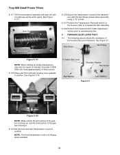
... portion of the gasket is facing in position. Fill the transmission assembly with the hex flange screws removed earlier using a 1/2" socket. 8.121. Hex Screw Idler Pulley Figure 8.117 NOTE: When refilling an empty transmission, use only GL-4 gear oil having a viscosity of SAE 85W-140. Set the front and rear transmission covers in the reverse order to operating the tiller. 9. Place new front and rear housing cover gaskets in . 8.119.
... portion of the gasket is facing in position. Fill the transmission assembly with the hex flange screws removed earlier using a 1/2" socket. 8.121. Hex Screw Idler Pulley Figure 8.117 NOTE: When refilling an empty transmission, use only GL-4 gear oil having a viscosity of SAE 85W-140. Set the front and rear transmission covers in the reverse order to operating the tiller. 9. Place new front and rear housing cover gaskets in . 8.119.


