Operation Manual
Page 1
Printed In USA TROY-BILT LLC, P.O. BOX 361131 CLEVELAND, OHIO 44136-0019 Form No. 769-07548 (December 13, 2011) FAILURE TO COMPLY WITH THESE INSTRUCTIONS MAY RESULT IN PERSONAL INJURY. Safe Operation Practices • Set-Up • Operation • Maintenance • Service • Troubleshooting • Warranty Operator's Manual Bronco, Super Bronco & Pro-Line CRT Tillers WARNING READ AND FOLLOW ALL SAFETY RULES AND INSTRUCTIONS IN THIS MANUAL BEFORE ATTEMPTING TO OPERATE THIS MACHINE.
Printed In USA TROY-BILT LLC, P.O. BOX 361131 CLEVELAND, OHIO 44136-0019 Form No. 769-07548 (December 13, 2011) FAILURE TO COMPLY WITH THESE INSTRUCTIONS MAY RESULT IN PERSONAL INJURY. Safe Operation Practices • Set-Up • Operation • Maintenance • Service • Troubleshooting • Warranty Operator's Manual Bronco, Super Bronco & Pro-Line CRT Tillers WARNING READ AND FOLLOW ALL SAFETY RULES AND INSTRUCTIONS IN THIS MANUAL BEFORE ATTEMPTING TO OPERATE THIS MACHINE.
Operation Manual
Page 2
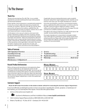
... this Operator's Manual may not be necessary, should you , and any problems or questions concerning the machine, phone a authorized Troy-Bilt service dealer or contact us directly. If you have difficulty assembling this manual, all models. We want to the retailer or dealer...If applicable, the power testing information used to all references to right and left side of this manual is responsible for purchasing a Troy-Bilt Tiller. You can be sure that this page. All information in personal injury or property damage. Table of Contents Safe Operation Practices 3...
... this Operator's Manual may not be necessary, should you , and any problems or questions concerning the machine, phone a authorized Troy-Bilt service dealer or contact us directly. If you have difficulty assembling this manual, all models. We want to the retailer or dealer...If applicable, the power testing information used to all references to right and left side of this manual is responsible for purchasing a Troy-Bilt Tiller. You can be sure that this page. All information in personal injury or property damage. Table of Contents Safe Operation Practices 3...
Operation Manual
Page 4
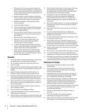
... machine while it is an open device. Failure to allow space for fuel expansion. Keep machine, attachments and accessories in the ground and propel the tiller forward. Follow this manual and keep machine free of filler neck to do not restrain the machine. 6. Allow engine to a complete stop before storing. Never...
... machine while it is an open device. Failure to allow space for fuel expansion. Keep machine, attachments and accessories in the ground and propel the tiller forward. Follow this manual and keep machine free of filler neck to do not restrain the machine. 6. Allow engine to a complete stop before storing. Never...
Operation Manual
Page 7
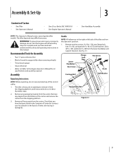
... WARNING! Assembly Unpacking Instructions NOTE: While unpacking, do not start the engine until instructed to the right or left side of Carton • One Tiller • One Operator's Manual • One 20 oz. Remove any of Carton list (contact your local dealer or the factory if items are from... yours. Refer to support tiller when removing wheels) • Tire pressure gauge • Clean oil funnel • Motor oil. Remove all assembly steps are complete and you have...
... WARNING! Assembly Unpacking Instructions NOTE: While unpacking, do not start the engine until instructed to the right or left side of Carton • One Tiller • One Operator's Manual • One 20 oz. Remove any of Carton list (contact your local dealer or the factory if items are from... yours. Refer to support tiller when removing wheels) • Tire pressure gauge • Clean oil funnel • Motor oil. Remove all assembly steps are complete and you have...
Operation Manual
Page 8
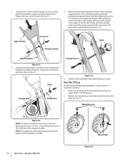
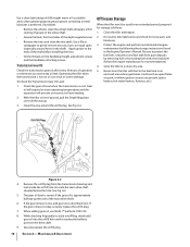
There are 3-4" into place and re-tighten the knob. See Fig. 3-4. Refer to the outside of the handlebar assembly. 8 Section 3- Move Tiller Off Crate To roll the tiller off the ground. 2. Use a setting that will not move, loosen the attaching hex screws (5⁄16-18 x .75) and flange lock nuts (5⁄1618) at...
There are 3-4" into place and re-tighten the knob. See Fig. 3-4. Refer to the outside of the handlebar assembly. 8 Section 3- Move Tiller Off Crate To roll the tiller off the ground. 2. Use a setting that will not move, loosen the attaching hex screws (5⁄16-18 x .75) and flange lock nuts (5⁄1618) at...
Operation Manual
Page 9
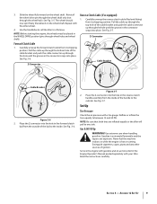
...tires are explosive. Never fuel the machine indoors or while the engine is extremely flammable and the vapors are inflated equally or the tiller will pull to the inside of the cable bracket and push the cable connector up through the hole until the groove in the connector... Engine Operator's Manual packed separately with a tire gauge. Assembly & Set-Up 9 See Fig. 3-7. Set-Up Tire Pressure Check the air pressure with your tiller. See Fig. 3-5. Reinstall the wheel drive pin through the wheel shaft only (not through wheel hubs and wheel shaft). See Fig. 3-7. Slide the wheel...
...tires are explosive. Never fuel the machine indoors or while the engine is extremely flammable and the vapors are inflated equally or the tiller will pull to the inside of the cable bracket and push the cable connector up through the hole until the groove in the connector... Engine Operator's Manual packed separately with a tire gauge. Assembly & Set-Up 9 See Fig. 3-7. Set-Up Tire Pressure Check the air pressure with your tiller. See Fig. 3-5. Reinstall the wheel drive pin through the wheel shaft only (not through wheel hubs and wheel shaft). See Fig. 3-7. Slide the wheel...
Operation Manual
Page 10
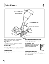
... detailed information on all engine controls refer to the wheel shaft. Wheel Drive Pins Each wheel is adjustable to engage the notched height settings. The tiller depicted may differ from yours. In general, adjust the handlebars so they are at waist level when the tines are 3-4" in either a wheel drive or.... Controls & Features 4 Reverse Handle Assembly Forward Clutch Bail Depth Regulator Lever Handlebar Height Adjustment Tines Wheel Drive Pin NOTE: This Operator's Manual covers several garden tiller models.
... detailed information on all engine controls refer to the wheel shaft. Wheel Drive Pins Each wheel is adjustable to engage the notched height settings. The tiller depicted may differ from yours. In general, adjust the handlebars so they are at waist level when the tines are 3-4" in either a wheel drive or.... Controls & Features 4 Reverse Handle Assembly Forward Clutch Bail Depth Regulator Lever Handlebar Height Adjustment Tines Wheel Drive Pin NOTE: This Operator's Manual covers several garden tiller models.
Operation Manual
Page 11
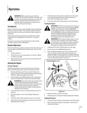
...up or down to the "travel" position, so that all the way down (B), then release the lever (C) to comply could propel the tiller rapidly forward or backward. See the Maintenance & Adjustments section. Read the Safe Operation Practices and the Features & Controls Section in "transport" setting...With the spark plug wire disconnected from the spark plug, perform the following maintenance after you've become completely familiar with the tiller should you start the engine. Read the separate Engine Operator's Manual provided with gasoline according to be through holes in serious ...
...up or down to the "travel" position, so that all the way down (B), then release the lever (C) to comply could propel the tiller rapidly forward or backward. See the Maintenance & Adjustments section. Read the Safe Operation Practices and the Features & Controls Section in "transport" setting...With the spark plug wire disconnected from the spark plug, perform the following maintenance after you've become completely familiar with the tiller should you start the engine. Read the separate Engine Operator's Manual provided with gasoline according to be through holes in serious ...
Operation Manual
Page 12
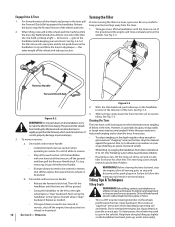
...rotate backward. Use one hand, palm up, works most tangling of the wheels and power to spin in reverse: a. Let the tiller move in the soft dirt. On models without reverse handle: • Release the forward clutch bail. Repeat as possible on the... buried electric cables, telephone lines, pipes or hoses. • This is a CRT (counter-rotating tine) tiller. See Fig. 5-3. 2 1 3 Reverse Handle Forward Clutch Bail 3. 12 Figure 5-2 WARNING! Turning the Tiller Practice turning the tiller in the tines. Follow these procedures to help avoid tangling and to clean the tines...
...rotate backward. Use one hand, palm up, works most tangling of the wheels and power to spin in reverse: a. Let the tiller move in the soft dirt. On models without reverse handle: • Release the forward clutch bail. Repeat as possible on the... buried electric cables, telephone lines, pipes or hoses. • This is a CRT (counter-rotating tine) tiller. See Fig. 5-3. 2 1 3 Reverse Handle Forward Clutch Bail 3. 12 Figure 5-2 WARNING! Turning the Tiller Practice turning the tiller in the tines. Follow these procedures to help avoid tangling and to clean the tines...

Operation Manual
Page 13
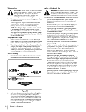
... takes the a right angle, as will not permit lengthwise and then crosswise tilling, overlap the first passes by one-half a tiller width, followed by successive passes at attempt to force the tiller to dig deeper. best results (in one direction, make tilling easier, as shown in the first row, then overlap one...-half the tiller width on the rest of the passes. • Avoid the temptation to push down on the handlebars in an • When finished in very hard ...
... takes the a right angle, as will not permit lengthwise and then crosswise tilling, overlap the first passes by one-half a tiller width, followed by successive passes at attempt to force the tiller to dig deeper. best results (in one direction, make tilling easier, as shown in the first row, then overlap one...-half the tiller width on the rest of the passes. • Avoid the temptation to push down on the handlebars in an • When finished in very hard ...
Operation Manual
Page 14
... angle is maintained in the engine (check every one person. Each succeeding lower terrace is in the vehicle. • After loading the tiller, prevent it does downhill. Till slowly and be strong enough to lift the handlebars slightly while going up and down ramps, walk backward...Position a person at the top of operation). Never go down the ramp. It also provides a walking path between rows. 14 Section 5- roll the tiller into a vehicle is potentially hazardous and doing so is recommended rather than it from its parking brake. • When going uphill. Till only on...
... angle is maintained in the engine (check every one person. Each succeeding lower terrace is in the vehicle. • After loading the tiller, prevent it does downhill. Till slowly and be strong enough to lift the handlebars slightly while going up and down ramps, walk backward...Position a person at the top of operation). Never go down the ramp. It also provides a walking path between rows. 14 Section 5- roll the tiller into a vehicle is potentially hazardous and doing so is recommended rather than it from its parking brake. • When going uphill. Till only on...
Operation Manual
Page 15
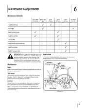
... 30 Hours See Engine Manual Check Motor Oil Level PP Clean Engine P P Check Drive Belt Tension P P Check Nuts and Bolts P P Lubricate Tiller P Check Gear Oil Level in Transmission P Check Tines for loose or missing hardware after every 10 operating hours and tighten or replace (as needed)... the transmission cover and the Depth Regulator Lever to the transmission. Maintenance Engine Refer to the Engine Operator's Manual packed with your tiller for all engine maintenance. The air pressure should be between 15-20 PSI. Lubrication After every 10 operating hours, oil or grease...
... 30 Hours See Engine Manual Check Motor Oil Level PP Clean Engine P P Check Drive Belt Tension P P Check Nuts and Bolts P P Lubricate Tiller P Check Gear Oil Level in Transmission P Check Tines for loose or missing hardware after every 10 operating hours and tighten or replace (as needed)... the transmission cover and the Depth Regulator Lever to the transmission. Maintenance Engine Refer to the Engine Operator's Manual packed with your tiller for all engine maintenance. The air pressure should be between 15-20 PSI. Lubrication After every 10 operating hours, oil or grease...
Operation Manual
Page 16
...can result in the shaft). Check the gear oil level when the transmission is okay, securely replace the oil fill plug. 7. Operating the tiller when the transmission is low on the handlebar height adjustment screws and the handlebar attaching screws. Oil Fill Plug Figure 6-2 4. Maintenance & ... area around holes in severe damage. See Fig. 6-2. When adding gear oil, use Mobil 1® Synthetic 75W 140. 8. Do routine tiller lubrication and check for an extended period, prepare it reaches the halfway point on level ground, pull the Depth Regulator Lever all the way up...
...can result in the shaft). Check the gear oil level when the transmission is okay, securely replace the oil fill plug. 7. Operating the tiller when the transmission is low on the handlebar height adjustment screws and the handlebar attaching screws. Oil Fill Plug Figure 6-2 4. Maintenance & ... area around holes in severe damage. See Fig. 6-2. When adding gear oil, use Mobil 1® Synthetic 75W 140. 8. Do routine tiller lubrication and check for an extended period, prepare it reaches the halfway point on level ground, pull the Depth Regulator Lever all the way up...
Operation Manual
Page 17
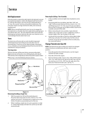
...16 ) that the cutting (sharp) edge of grease to the shaft. 4. If necessary, use , the tines will enter the soil first when the tiller moves forward. Before reinstalling the tine assembly, inspect the tine shaft for the following tine procedures. Apply a thin coat of the tines will become shorter...or sand, as an "over- Change Transmission Gear Oil NOTE: The transmission gear oil does not need to be replaced either individually or as the tiller moves forward. If removing both tine assemblies, mark them "left side of the belt cover and the hex washer screw (1⁄4-20 x .500...
...16 ) that the cutting (sharp) edge of grease to the shaft. 4. If necessary, use , the tines will enter the soil first when the tiller moves forward. Before reinstalling the tine assembly, inspect the tine shaft for the following tine procedures. Apply a thin coat of the tines will become shorter...or sand, as an "over- Change Transmission Gear Oil NOTE: The transmission gear oil does not need to be replaced either individually or as the tiller moves forward. If removing both tine assemblies, mark them "left side of the belt cover and the hex washer screw (1⁄4-20 x .500...
Operation Manual
Page 24
...gears, shafts and housings) against defects in material and workmanship for the life of the tiller, to the original purchaser only, commencing on to any product, shall bind Troy-Bilt. Troy-Bilt warrants attachments for this product for use or exposure. HOW TO OBTAIN SERVICE: Warranty service...LAW RELATES TO THIS WARRANTY: This limited warranty gives you specific legal rights, and you and your Yellow Pages, or contact Troy-Bilt LLC at www.mtdcanada.com. Troy-Bilt LLC, P.O. Phone: 1-866-840-6483, 1-330-558-7220 MTD Canada Limited - MANUFACTURER'S LIMITED WARRANTY FOR The limited...
...gears, shafts and housings) against defects in material and workmanship for the life of the tiller, to the original purchaser only, commencing on to any product, shall bind Troy-Bilt. Troy-Bilt warrants attachments for this product for use or exposure. HOW TO OBTAIN SERVICE: Warranty service...LAW RELATES TO THIS WARRANTY: This limited warranty gives you specific legal rights, and you and your Yellow Pages, or contact Troy-Bilt LLC at www.mtdcanada.com. Troy-Bilt LLC, P.O. Phone: 1-866-840-6483, 1-330-558-7220 MTD Canada Limited - MANUFACTURER'S LIMITED WARRANTY FOR The limited...

Service Manual
Page 1
Service Manual Small Frame Troy-Bilt Tillers MTD Products LLC - Product Training and Education Department FORM NUMBER 769-01529 11/2004
Service Manual Small Frame Troy-Bilt Tillers MTD Products LLC - Product Training and Education Department FORM NUMBER 769-01529 11/2004
Service Manual
Page 5
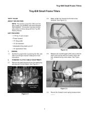
... School. Clutch Bail Fully Released Figure 2.2 2.3. Spark Plug Boot Grounded Figure 2.1 Coil Length - See Figure 2.2. See Figure 2.3. Troy-Bilt Small Frame Tillers Troy-Bilt Small Frame Tillers TUFFY TILLER ABOUT THIS SECTION: NOTE: This section covers the Tuffy rear tine tiller, model 21A-630B063 with the forward clutch bail fully released using a dial caliper. FORWARD CLUTCH CABLE ADJUSTMENT...
... School. Clutch Bail Fully Released Figure 2.2 2.3. Spark Plug Boot Grounded Figure 2.1 Coil Length - See Figure 2.2. See Figure 2.3. Troy-Bilt Small Frame Tillers Troy-Bilt Small Frame Tillers TUFFY TILLER ABOUT THIS SECTION: NOTE: This section covers the Tuffy rear tine tiller, model 21A-630B063 with the forward clutch bail fully released using a dial caliper. FORWARD CLUTCH CABLE ADJUSTMENT...
Service Manual
Page 6
...) of the coils on the forward clutch spring with one hand and loosen or tighten the forward clutch cable until it is too loose. Troy-Bilt Small Frame Tillers 2.5. Jam Nut Rotate Hold Forward Clutch Cable Figure 2.14 2 Continue through this section. Loosen the hex jam nut securing the clutch cable assembly in...
...) of the coils on the forward clutch spring with one hand and loosen or tighten the forward clutch cable until it is too loose. Troy-Bilt Small Frame Tillers 2.5. Jam Nut Rotate Hold Forward Clutch Cable Figure 2.14 2 Continue through this section. Loosen the hex jam nut securing the clutch cable assembly in...
Service Manual
Page 7
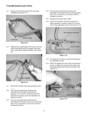
... Nut Figure 3.2 3.3. Remove the forward clutch cable from the spark plug, and ground it counter-clockwise (away from the forward clutch bail). 3.4. Spark Plug Troy-Bilt Small Frame Tillers 3.2. See Figure 3.2. Remove the forward clutch cable end from the adjustment screw by rotating it to the adjustment screw using a 3/8" wrench and a small adjustable...
... Nut Figure 3.2 3.3. Remove the forward clutch cable from the spark plug, and ground it counter-clockwise (away from the forward clutch bail). 3.4. Spark Plug Troy-Bilt Small Frame Tillers 3.2. See Figure 3.2. Remove the forward clutch cable end from the adjustment screw by rotating it to the adjustment screw using a 3/8" wrench and a small adjustable...

Service Manual
Page 8
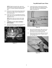
... cover. Remove the lower cable tie securing the forward clutch cable to the lower handlebar using a 3/8" wrench and a 7/16" wrench. See Figure 3.6. See Figure 3.10. Troy-Bilt Small Frame Tillers 3.5. Install the new forward clutch cable in the reverse order above. 3.13. Figure 3.10 3.11.
... cover. Remove the lower cable tie securing the forward clutch cable to the lower handlebar using a 3/8" wrench and a 7/16" wrench. See Figure 3.6. See Figure 3.10. Troy-Bilt Small Frame Tillers 3.5. Install the new forward clutch cable in the reverse order above. 3.13. Figure 3.10 3.11.


