
User Guide
Page 75
... which can be installed in good condition. Installing a memory module Additional memory modules can provide for this occurs, contact Toshiba's support center at (800) 457-7777. You will not boot beyond the BIOS memory check. When additional memory is added, or original memory replaced, it is recommended that is in the memory...
... which can be installed in good condition. Installing a memory module Additional memory modules can provide for this occurs, contact Toshiba's support center at (800) 457-7777. You will not boot beyond the BIOS memory check. When additional memory is added, or original memory replaced, it is recommended that is in the memory...

User Guide
Page 128
... green when it maintains this information for up to a month when the computer is powered off . The RTC battery powers the System Time Clock and BIOS memory used to its full capacity, wait until it is extremely hot or cold. To ensure that the battery charges to store your computer, plug...
... green when it maintains this information for up to a month when the computer is powered off . The RTC battery powers the System Time Clock and BIOS memory used to its full capacity, wait until it is extremely hot or cold. To ensure that the battery charges to store your computer, plug...

User Guide
Page 165
Shows the BIOS version ❖ Password - If data does not appear on the display you are using after starting in LCD display NOTE When the computer restarts, it ... default settings for the built-in Standby Mode, press Fn + F5. ❖ CPU - Allows you to configure the parallel port default settings ❖ Display - 165 Toshiba Utilities Toshiba HW Setup Sample HW Setup Toshiba HW Setup has the following tabs: ❖ General -
Shows the BIOS version ❖ Password - If data does not appear on the display you are using after starting in LCD display NOTE When the computer restarts, it ... default settings for the built-in Standby Mode, press Fn + F5. ❖ CPU - Allows you to configure the parallel port default settings ❖ Display - 165 Toshiba Utilities Toshiba HW Setup Sample HW Setup Toshiba HW Setup has the following tabs: ❖ General -
User Guide
Page 193
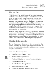
.... 6 To view the properties, double-click the device. Plug and Play is easy. However, if you install an older (legacy) device that helps the system BIOS (basic input/output system) and Windows XP to automatically assign system resources to it. In theory, if every device connected to the device. Properties include...
.... 6 To view the properties, double-click the device. Plug and Play is easy. However, if you install an older (legacy) device that helps the system BIOS (basic input/output system) and Windows XP to automatically assign system resources to it. In theory, if every device connected to the device. Properties include...

User Guide
Page 241
...; Display-Allows you to change various default settings for the built-in LCD display. 241 Windows 2000 Supplemental Information Toshiba Utilities Sample Toshiba HW Setup Toshiba HW Setup contains these tabs: ❖ General-Shows the BIOS version, memory configuration, and Hard Disk Drive (HDD) mode. ❖ Password-Allows you to set the CPU Frequency...
...; Display-Allows you to change various default settings for the built-in LCD display. 241 Windows 2000 Supplemental Information Toshiba Utilities Sample Toshiba HW Setup Toshiba HW Setup contains these tabs: ❖ General-Shows the BIOS version, memory configuration, and Hard Disk Drive (HDD) mode. ❖ Password-Allows you to set the CPU Frequency...

User Guide
Page 261
Glossary TECHNICAL NOTE: Some features defined in this glossary may appear in this user's guide. AC alternating current BIOS basic input/output system bps bits per second CD compact disc CD-ROM compact disc read-only memory CMOS complementary metal-oxide semiconductor COM1 communications port 1 (serial port) COM2 communications port 2 (serial port) CPU central processing unit DC direct current 261 Acronyms The following acronyms may not be available on your computer.
Glossary TECHNICAL NOTE: Some features defined in this glossary may appear in this user's guide. AC alternating current BIOS basic input/output system bps bits per second CD compact disc CD-ROM compact disc read-only memory CMOS complementary metal-oxide semiconductor COM1 communications port 1 (serial port) COM2 communications port 2 (serial port) CPU central processing unit DC direct current 261 Acronyms The following acronyms may not be available on your computer.

User Guide
Page 264
...devices. See also bits per second). boot disk-See system disk. See also bit, gigabyte, kilobyte, megabyte. basic input/output system (BIOS)-See BIOS. Baud rate is the number of signal changes per second (bps)-A way of measuring the speed at which the computer accesses its bootstraps... central processing unit (CPU) communicates with other parts of the computer. The basic measure used by its disk drives to another. BIOS (basic input/output system)-Basic instructions, stored in readonly memory (ROM), containing the information the computer needs in the diskette drive ...
...devices. See also bits per second). boot disk-See system disk. See also bit, gigabyte, kilobyte, megabyte. basic input/output system (BIOS)-See BIOS. Baud rate is the number of signal changes per second (bps)-A way of measuring the speed at which the computer accesses its bootstraps... central processing unit (CPU) communicates with other parts of the computer. The basic measure used by its disk drives to another. BIOS (basic input/output system)-Basic instructions, stored in readonly memory (ROM), containing the information the computer needs in the diskette drive ...

User Guide
Page 273
... start the computer. On your open applications and to continue from where you left off when you turn off the computer without exiting your computer's BIOS, which is essential instructions the computer reads when you to turn the computer on it up. Standby-A feature of memory is receiving power. A system disk...
... start the computer. On your open applications and to continue from where you left off when you turn off the computer without exiting your computer's BIOS, which is essential instructions the computer reads when you to turn the computer on it up. Standby-A feature of memory is receiving power. A system disk...

User Guide
Page 276
... power usage mode 245 real-time clock (RTC) 127 removing 134 status 47 troubleshooting 195 unlocking 133 battery power Hibernation mode 230 Standby mode 230 BIOS version 241 boot priority 242 button start 142 buttons CD or DVD controls 147 CD Player 148 C caps lock key 48 light 48 CD playing...
... power usage mode 245 real-time clock (RTC) 127 removing 134 status 47 troubleshooting 195 unlocking 133 battery power Hibernation mode 230 Standby mode 230 BIOS version 241 boot priority 242 button start 142 buttons CD or DVD controls 147 CD Player 148 C caps lock key 48 light 48 CD playing...

Maintenance Manual
Page 4
... the LCD module q Board layout q Pin assignments q Keyboard scan/character codes q Key layout q Wiring diagrams q BIOS Rewrite Procedures q Reliability iv TECRA M1 Maintenance Manual (960 -436) Appendices The appendices describe the following parts: Chapter 1 Hardware Overview describes the TECRA M1 system unit and each FRU. Chapter 4 Replacement Procedures describes the removal and replacement of the...
... the LCD module q Board layout q Pin assignments q Keyboard scan/character codes q Key layout q Wiring diagrams q BIOS Rewrite Procedures q Reliability iv TECRA M1 Maintenance Manual (960 -436) Appendices The appendices describe the following parts: Chapter 1 Hardware Overview describes the TECRA M1 system unit and each FRU. Chapter 4 Replacement Procedures describes the removal and replacement of the...

Maintenance Manual
Page 12
Appendices Appendix A Appendix B Appendix C Appendix D Appendix E Appendix F Appendix G Appendix H Appendix I Handling the LCD Module A-1 Board Layout B-1 Pin Assignments C-1 Character Codes D-1 Key Layout...E-1 Reliability ...F-1 BIOS Rewrite Procedures G-1 EC/KBC Rewrite Procedures H-1 Reliability ...I-1 xii TECRA M1 Maintenance Manual (960 -436)
Appendices Appendix A Appendix B Appendix C Appendix D Appendix E Appendix F Appendix G Appendix H Appendix I Handling the LCD Module A-1 Board Layout B-1 Pin Assignments C-1 Character Codes D-1 Key Layout...E-1 Reliability ...F-1 BIOS Rewrite Procedures G-1 EC/KBC Rewrite Procedures H-1 Reliability ...I-1 xii TECRA M1 Maintenance Manual (960 -436)

Maintenance Manual
Page 28
... Port Interface: adheres to 2GB (2,048MB) is available. • DDR-SDRAM (Double Data Rate - I /O) - Hub Link Interface - Power Management Controller TECRA M1 Maintenance Manual (960-436) 1-11 DRAM Controller: DDR200/DDR266 Support, 1GB max - LPC Interface (EC/KBC, Super I /O APIC (ACPI 1.06) -... is used . • This gate array has the following features: - PCI Rev2.2 Interface (6 PCI REQ/GNT Pairs) - FWH Interface (BIOS) - 1.2 System Unit Block Diagram 1 Hardware Overview - Expansion up to AGP2.0, AGP ×4 mode - BusMaster IDE Controller (Ultra ATA 100...
... Port Interface: adheres to 2GB (2,048MB) is available. • DDR-SDRAM (Double Data Rate - I /O) - Hub Link Interface - Power Management Controller TECRA M1 Maintenance Manual (960-436) 1-11 DRAM Controller: DDR200/DDR266 Support, 1GB max - LPC Interface (EC/KBC, Super I /O APIC (ACPI 1.06) -... is used . • This gate array has the following features: - PCI Rev2.2 Interface (6 PCI REQ/GNT Pairs) - FWH Interface (BIOS) - 1.2 System Unit Block Diagram 1 Hardware Overview - Expansion up to AGP2.0, AGP ×4 mode - BusMaster IDE Controller (Ultra ATA 100...

Maintenance Manual
Page 29
... has the following functions and components. - Vpp: 3.3V and 12V for fast programming (80 hours maximum) • 4Mbits of flash memory for LAN BIOS. 1-12 TECRA M1 Maintenance Manual (960-436) SmartMedia controller (SMHC Ver.01/SMIL1.0) - Address/Address-Multiplexed (A/A Mux) interface/mode - AC'97 2.2 Interface - Q ...3V ± 0.3V - Two configurable interfaces - 4Mbits of flash memory are used as shown below: - 64KB are used for VGA-BIOS. - 192KB are used for system BIOS. - 8KB are used for plug and play data area. - 8KB are used for password security. - 16KB are used for boot strap...
... has the following functions and components. - Vpp: 3.3V and 12V for fast programming (80 hours maximum) • 4Mbits of flash memory for LAN BIOS. 1-12 TECRA M1 Maintenance Manual (960-436) SmartMedia controller (SMHC Ver.01/SMIL1.0) - Address/Address-Multiplexed (A/A Mux) interface/mode - AC'97 2.2 Interface - Q ...3V ± 0.3V - Two configurable interfaces - 4Mbits of flash memory are used as shown below: - 64KB are used for VGA-BIOS. - 192KB are used for system BIOS. - 8KB are used for plug and play data area. - 8KB are used for password security. - 16KB are used for boot strap...

Maintenance Manual
Page 48
...8226; Battery icon (sets LED to orange or green) • Faulty power supply by low battery 5. Indicates the following aspects of power supply 6. TECRA M1 Maintenance Manual (960-436) 1-31 Interface for battery pack charging 3. Checks power input to determine: • Whether the AC adaptor is connected to ...Supply 1 Hardware Overview 1.11 Power Supply The power supply supplies many different voltages to the system board and performs the following : • BIOS via EC/KBC • Function mode of the logic system • Power supply to gate arrays • Power on/off 4.
...8226; Battery icon (sets LED to orange or green) • Faulty power supply by low battery 5. Indicates the following aspects of power supply 6. TECRA M1 Maintenance Manual (960-436) 1-31 Interface for battery pack charging 3. Checks power input to determine: • Whether the AC adaptor is connected to ...Supply 1 Hardware Overview 1.11 Power Supply The power supply supplies many different voltages to the system board and performs the following : • BIOS via EC/KBC • Function mode of the logic system • Power supply to gate arrays • Power on/off 4.

Maintenance Manual
Page 77
...is no error message, go to Procedure 3. These errors occur when the system configuration preserved in the BIOS ROM. If any other error message displays, perform Check 2. (a) *** Bad HDD type *** Check... display, perform Check 1. Then press [F1] key ...... (c) *** Bad configuration *** Check system. q If Toshiba MS-DOS or Windows Me is turned on the screen, press F1 as the message instruc ts, returns all... Then the system reboots. Then press [F1] key ...... TECRA M1 Maintenance Manual (960 -436) 2-17 Then press [F1] key ...... (e) *** Bad time function *** Check system.
...is no error message, go to Procedure 3. These errors occur when the system configuration preserved in the BIOS ROM. If any other error message displays, perform Check 2. (a) *** Bad HDD type *** Check... display, perform Check 1. Then press [F1] key ...... (c) *** Bad configuration *** Check system. q If Toshiba MS-DOS or Windows Me is turned on the screen, press F1 as the message instruc ts, returns all... Then the system reboots. Then press [F1] key ...... TECRA M1 Maintenance Manual (960 -436) 2-17 Then press [F1] key ...... (e) *** Bad time function *** Check system.

Maintenance Manual
Page 79
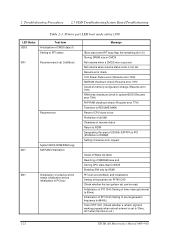
... IRT (Initial Reliability Test) status and test status by the IRT test, the printer port LED displays an error code after the IRT test ends. TECRA M1 Maintenance Manual (960 -436) 2-19 Read the LED status from binary to Procedure 4. 5. In this instance, the IRT indicates an error has been detected during...
... IRT (Initial Reliability Test) status and test status by the IRT test, the printer port LED displays an error code after the IRT test ends. TECRA M1 Maintenance Manual (960 -436) 2-19 Read the LED status from binary to Procedure 4. 5. In this instance, the IRT indicates an error has been detected during...

Maintenance Manual
Page 80
... line Initialization for special register and Intel chip set PIT CH0 initialization (for SDRAM initialization Setting FDC prohibition 2-20 TECRA M1 Maintenance Manual (960 -436) Setting of base for Power Management I/O Space Enabling BIOS writing Serial interrupt control Disabling BIOS rewrite protection Enabling SM Bus I/O space Enabling SM Bus access Opening work I/O for HOLD_ON...
... line Initialization for special register and Intel chip set PIT CH0 initialization (for SDRAM initialization Setting FDC prohibition 2-20 TECRA M1 Maintenance Manual (960 -436) Setting of base for Power Management I/O Space Enabling BIOS writing Serial interrupt control Disabling BIOS rewrite protection Enabling SM Bus I/O space Enabling SM Bus access Opening work I/O for HOLD_ON...

Maintenance Manual
Page 81
... CMOS access test Battery level check of CMOS CMOS checksum check Message Enabling system speaker Disabling mute Setting volume to max CEC/KBC UPDATE/DAMAGED, BIOS UPDATE/DAMAGED Disabling USB Sound beep Waiting for key input FDC reset Setting of parameter for 2HD (1.44MB), transmission rate Reading first sector Setting of... Boot) (HLT when the DRAM type is 0) (HLT when the stack area can not be used.) (at Cold Boot) (HLT when an error is detected.) TECRA M1 Maintenance Manual (960 -436) 2-21
... CMOS access test Battery level check of CMOS CMOS checksum check Message Enabling system speaker Disabling mute Setting volume to max CEC/KBC UPDATE/DAMAGED, BIOS UPDATE/DAMAGED Disabling USB Sound beep Waiting for key input FDC reset Setting of parameter for 2HD (1.44MB), transmission rate Reading first sector Setting of... Boot) (HLT when the DRAM type is 0) (HLT when the stack area can not be used.) (at Cold Boot) (HLT when an error is detected.) TECRA M1 Maintenance Manual (960 -436) 2-21
Maintenance Manual
Page 82
...item Initialization of CMOS data (1) Setting of IRT status 03H Resume branch (at Cold Boot) Resume error System BIOS ROM/RAM copy 04H SM RAM initialization 05H Initialization of a device which needs initialization before initialization of PCI bus ...check (Resume error 73H) Check of memory configuration change (Resume error 73H) RAM area checksum check in system BIOS (Resume error 79H) PnP RAM checksum check (Resume error 77H) Transition to RESUME-MAIN Reset of CPU clock... a refresh signal is working properly when refresh interval is out.) 2-22 TECRA M1 Maintenance Manual (960 -436)
...item Initialization of CMOS data (1) Setting of IRT status 03H Resume branch (at Cold Boot) Resume error System BIOS ROM/RAM copy 04H SM RAM initialization 05H Initialization of a device which needs initialization before initialization of PCI bus ...check (Resume error 73H) Check of memory configuration change (Resume error 73H) RAM area checksum check in system BIOS (Resume error 79H) PnP RAM checksum check (Resume error 77H) Transition to RESUME-MAIN Reset of CPU clock... a refresh signal is working properly when refresh interval is out.) 2-22 TECRA M1 Maintenance Manual (960 -436)

Maintenance Manual
Page 85
... boot-up Message Storing CMOS error status in IRT error status buffer Start of TIMER initialization Initialization of buffer for power save Update of system BIOS (model name, EDID of the LCD) Waiting for the end of VGA chip initialization (Boot) Check of exceptional cases in protected mode (Boot) (Boot) (Boot... Storing the value of 40:00h (for SIO save/store) Font address setting for resume password Setting of parameter for character repeat on a USB keyboard TECRA M1 Maintenance Manual (960 -436) 2-25
... boot-up Message Storing CMOS error status in IRT error status buffer Start of TIMER initialization Initialization of buffer for power save Update of system BIOS (model name, EDID of the LCD) Waiting for the end of VGA chip initialization (Boot) Check of exceptional cases in protected mode (Boot) (Boot) (Boot... Storing the value of 40:00h (for SIO save/store) Font address setting for resume password Setting of parameter for character repeat on a USB keyboard TECRA M1 Maintenance Manual (960 -436) 2-25


