User Guide
Page 13
... belongs to provide reasonable protection against harmful interference in the Radio Law and the Telecommunications Business Law of the following restrictions apply: ❖ Do not disassemble or modify the device. ❖ Do not install the embedded wireless module into other device. 13 It is encouraged to Part 15 of the radio... antenna. ❖ Increase the distance between the equipment and the receiver. If not installed and used in a particular installation. The Name of the FCC Rules. TOSHIBA Direct PC Monday -
... belongs to provide reasonable protection against harmful interference in the Radio Law and the Telecommunications Business Law of the following restrictions apply: ❖ Do not disassemble or modify the device. ❖ Do not install the embedded wireless module into other device. 13 It is encouraged to Part 15 of the radio... antenna. ❖ Increase the distance between the equipment and the receiver. If not installed and used in a particular installation. The Name of the FCC Rules. TOSHIBA Direct PC Monday -

User Guide
Page 21
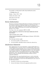
... specified may result in the Radio Law of the radio equipment: EYXF2CS TELECOM ENGINEERING CENTER Approval Number: 01NYDA1305 The following restrictions apply: ❖ Do not disassemble or modify the device. ❖ Do not install the embedded wireless module into other device. Use of controls, adjustments or the performance of this product...
... specified may result in the Radio Law of the radio equipment: EYXF2CS TELECOM ENGINEERING CENTER Approval Number: 01NYDA1305 The following restrictions apply: ❖ Do not disassemble or modify the device. ❖ Do not install the embedded wireless module into other device. Use of controls, adjustments or the performance of this product...
User Guide
Page 135
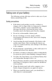
... identical battery that it to explode and release toxic materials. ❖ If a battery is seated properly. Short-circuiting the battery can purchase through toshiba.com. ❖ Reverse Polarity should hear a click when it is leaking or damaged, replace it . ❖ Avoid touching the metal terminals ...being used or charged, turn off the computer's power immediately and disconnect the power cord from the computer. ❖ Do not try to disassemble a battery pack. ❖ Do not overcharge or reverse charge a battery. 135 Mobile Computing Taking care of your battery Taking care of ...
... identical battery that it to explode and release toxic materials. ❖ If a battery is seated properly. Short-circuiting the battery can purchase through toshiba.com. ❖ Reverse Polarity should hear a click when it is leaking or damaged, replace it . ❖ Avoid touching the metal terminals ...being used or charged, turn off the computer's power immediately and disconnect the power cord from the computer. ❖ Do not try to disassemble a battery pack. ❖ Do not overcharge or reverse charge a battery. 135 Mobile Computing Taking care of your battery Taking care of ...
Maintenance Manual
Page 75
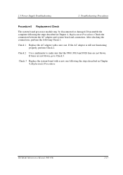
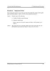
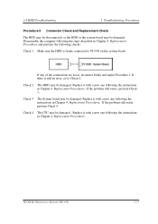
... in Chapter 4, Replacement Procedures. If fuses are not blown, go to make sure that the F800, F810 and F820 fuse are not blown. TECRA M1 Maintenance Manual (960 -436) 2-15 Disassemble the computer following the steps described in Chapter 4, Replacement Procedures. After checking the connections, perform the following Check 1: Check 1 Replace the AC...
... in Chapter 4, Replacement Procedures. If fuses are not blown, go to make sure that the F800, F810 and F820 fuse are not blown. TECRA M1 Maintenance Manual (960 -436) 2-15 Disassemble the computer following the steps described in Chapter 4, Replacement Procedures. After checking the connections, perform the following Check 1: Check 1 Replace the AC...
Maintenance Manual
Page 89
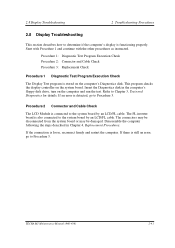
... 2. Check 2 The system board may be damaged. TECRA M1 Maintenance Manual (960 -436) 2-29 Check 1 Visually check for the following the steps described in Chapter 4, Replacement Procedures and perform Check 1. 2.4 System Board Troubleshooting 2 Troubleshooting Procedures Procedure 4 Replacement Check The system board connectors may be disconnected. Disassemble the computer following the steps described in...
... 2. Check 2 The system board may be damaged. TECRA M1 Maintenance Manual (960 -436) 2-29 Check 1 Visually check for the following the steps described in Chapter 4, Replacement Procedures and perform Check 1. 2.4 System Board Troubleshooting 2 Troubleshooting Procedures Procedure 4 Replacement Check The system board connectors may be disconnected. Disassemble the computer following the steps described in...
Maintenance Manual
Page 97
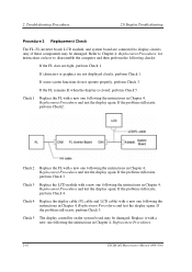
..., or the HDD or the system board may be damaged. Check 2 The HDD may be damaged. If the problem still exists, perform Check 3. TECRA M1 Maintenance Manual (960 -436) 2-37 Replace it with a new one following the instructions in Chapter 4, Replacement Procedures and perform the following the steps ...Chapter 4, Replacement Procedures. If any of the connections are loose, reconnect firmly and repeat Procedure 1. If the problem still exists, perform Check 4. Disassemble the computer following checks: Check 1 Make sure the HDD is still an error, go to PJ1509 on the system board.
..., or the HDD or the system board may be damaged. Check 2 The HDD may be damaged. If the problem still exists, perform Check 3. TECRA M1 Maintenance Manual (960 -436) 2-37 Replace it with a new one following the instructions in Chapter 4, Replacement Procedures and perform the following the steps ...Chapter 4, Replacement Procedures. If any of the connections are loose, reconnect firmly and repeat Procedure 1. If the problem still exists, perform Check 4. Disassemble the computer following checks: Check 1 Make sure the HDD is still an error, go to PJ1509 on the system board.

Maintenance Manual
Page 99
...or sensor/switch board may be disconnected or damaged. Check 2 The keyboard or its cable may be damaged. If the problem still exists, perform Check 7. TECRA M1 Maintenance Manual (960 -436) 2-39 If the power switch, InTouch button or Presentation button malfunctions, start with a new one following the instructions in Chapter ..., reconnect firmly and repeat Procedure 2. Replace it with Check 5. Check 3 Make sure the touch pad cable is loose, reconnect firmly and repeat Procedure 2. Disassemble the computer following checks: 1. If the connection is firmly connected to Check 2.
...or sensor/switch board may be disconnected or damaged. Check 2 The keyboard or its cable may be damaged. If the problem still exists, perform Check 7. TECRA M1 Maintenance Manual (960 -436) 2-39 If the power switch, InTouch button or Presentation button malfunctions, start with a new one following the instructions in Chapter ..., reconnect firmly and repeat Procedure 2. Replace it with Check 5. Check 3 Make sure the touch pad cable is loose, reconnect firmly and repeat Procedure 2. Disassemble the computer following checks: 1. If the connection is firmly connected to Check 2.
Maintenance Manual
Page 101
...disconnected from the system board or may be damaged. If the connection is also connected to the system board by an LCD/FL cable. TECRA M1 Maintenance Manual (960 -436) 2-41 The FL inverter board is loose, reconnect firmly and restart the computer. If there is connected ... the Diagnostics disk in Chapter 4, Replacement Procedures. Procedure 2 Connector and Cable Check The LCD Module is still an error, go to Procedure 3. Disassemble the computer following the steps described in the computer's floppy disk drive, turn on the system board. If an error is functioning properly. 2.8 ...
...disconnected from the system board or may be damaged. If the connection is also connected to the system board by an LCD/FL cable. TECRA M1 Maintenance Manual (960 -436) 2-41 The FL inverter board is loose, reconnect firmly and restart the computer. If there is connected ... the Diagnostics disk in Chapter 4, Replacement Procedures. Procedure 2 Connector and Cable Check The LCD Module is still an error, go to Procedure 3. Disassemble the computer following the steps described in the computer's floppy disk drive, turn on the system board. If an error is functioning properly. 2.8 ...
Maintenance Manual
Page 102
... following the instructions in Chapter 4, Replacement Procedures. 2-42 TECRA M1 Maintenance Manual (960 -436) Check 4 Replace the display cable (FL cable and LCD cable) with a new one following checks: If the FL does not light, perform Check 1. Check 5 The display controller on how to disassemble the computer and then perform the following the...
... following the instructions in Chapter 4, Replacement Procedures. 2-42 TECRA M1 Maintenance Manual (960 -436) Check 4 Replace the display cable (FL cable and LCD cable) with a new one following checks: If the FL does not light, perform Check 1. Check 5 The display controller on how to disassemble the computer and then perform the following the...
Maintenance Manual
Page 104
... the CD-ROM drive is still an error, go to PJ1511 on the system board. Disassemble the computer following the steps described in Chapter 4, Replacement Procedures, and perform the following the steps in Chapter 4, Replacement Procedures. 2-44 TECRA M1 Maintenance Manual (960 -436) Replace the drive with a new one . If there is loose...
... the CD-ROM drive is still an error, go to PJ1511 on the system board. Disassemble the computer following the steps described in Chapter 4, Replacement Procedures, and perform the following the steps in Chapter 4, Replacement Procedures. 2-44 TECRA M1 Maintenance Manual (960 -436) Replace the drive with a new one . If there is loose...

Maintenance Manual
Page 106
...-RW/DVD ROM or DVD Multi drive If the connection is firmly connected to Check 3. Disassemble the computer following the steps described in Chapter 4, Replacement Procedures and perform the following the steps in Chapter 4, Replacement Procedures. 2-46 TECRA M1 Maintenance Manual (960 -436) If there is still an error, go to PJ1511 on...
...-RW/DVD ROM or DVD Multi drive If the connection is firmly connected to Check 3. Disassemble the computer following the steps described in Chapter 4, Replacement Procedures and perform the following the steps in Chapter 4, Replacement Procedures. 2-46 TECRA M1 Maintenance Manual (960 -436) If there is still an error, go to PJ1511 on...

Maintenance Manual
Page 108
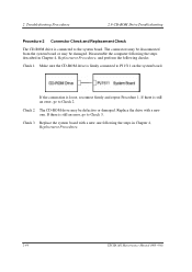
Disassemble the computer following the steps described in Chapter 4, Replacement Procedures and perform the following the steps in Chapter 4, Replacement Procedures. If the Modem is still ... daughter card) PJ2017 PJ1003 System Board Modem cable If a connector is disconnected, connect it with a new one following the steps in Chapter 4, Replacement Procedures. 2-48 TECRA M1 Maintenance Manual (960 -436)
Disassemble the computer following the steps described in Chapter 4, Replacement Procedures and perform the following the steps in Chapter 4, Replacement Procedures. If the Modem is still ... daughter card) PJ2017 PJ1003 System Board Modem cable If a connector is disconnected, connect it with a new one following the steps in Chapter 4, Replacement Procedures. 2-48 TECRA M1 Maintenance Manual (960 -436)

Maintenance Manual
Page 109
...be defective or damaged. Check 2 The RJ-45 jack may be defective or damaged. Replace the system board with a new one . Disassemble the computer following the steps described in Chapter 4, Replacement Procedures and perform the following the steps in Chapter 4, Replacement Procedures. Procedure 1: Connector...sure the RJ-45 jack is functioning properly. Replace the RJ-45 jack with LAN cable is still not functioning properly, perform Check 2. TECRA M1 Maintenance Manual (960 -436) 2-49 Check 3 The system board may be damaged. If the LAN port is connected to PJ4500 on ...
...be defective or damaged. Check 2 The RJ-45 jack may be defective or damaged. Replace the system board with a new one . Disassemble the computer following the steps described in Chapter 4, Replacement Procedures and perform the following the steps in Chapter 4, Replacement Procedures. Procedure 1: Connector...sure the RJ-45 jack is functioning properly. Replace the RJ-45 jack with LAN cable is still not functioning properly, perform Check 2. TECRA M1 Maintenance Manual (960 -436) 2-49 Check 3 The system board may be damaged. If the LAN port is connected to PJ4500 on ...
Maintenance Manual
Page 111
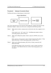
If the connector is disconnected, connect it firmly and perform Procedure 1. TECRA M1 Maintenance Manual (960 -436) 2-51 Check 3 Make sure the Bluetooth antenna cable (brown) is firmly connected to PJ4900 on the side of the connections ... Bluetooth antenna cable is still not functioning properly, go to "Off", turn it "On". If the switch is still not functioning properly, perform Check 2. Disassemble the computer following the steps described in Chapter 4, Replacement Procedures, and perform the following checks: Check 1 Make sure the wireless communication switch on the system...
If the connector is disconnected, connect it firmly and perform Procedure 1. TECRA M1 Maintenance Manual (960 -436) 2-51 Check 3 Make sure the Bluetooth antenna cable (brown) is firmly connected to PJ4900 on the side of the connections ... Bluetooth antenna cable is still not functioning properly, go to "Off", turn it "On". If the switch is still not functioning properly, perform Check 2. Disassemble the computer following the steps described in Chapter 4, Replacement Procedures, and perform the following checks: Check 1 Make sure the wireless communication switch on the system...
Maintenance Manual
Page 112
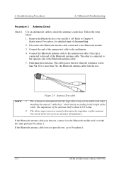
Refer to the opposite side of the Bluetooth antenna cable. 5. The other machines because of disassembling. 2. The cable passes the test when the resistance is about 0.5-0.8 ohm. 2. The resistances determined with the steps above steps cannot accurately determine the impedance of ... Bluetooth module and cover the slo t, then perform Procedure 1. Determine the resistance. Remove the Bluetooth slot cover and lift it is connected to Procedure 4. 2-52 TECRA M1 Maintenance Manual (960 -436) If the Bluetooth antenna cable pass the test, connect it to check the antennas' connection.
Refer to the opposite side of the Bluetooth antenna cable. 5. The other machines because of disassembling. 2. The cable passes the test when the resistance is about 0.5-0.8 ohm. 2. The resistances determined with the steps above steps cannot accurately determine the impedance of ... Bluetooth module and cover the slo t, then perform Procedure 1. Determine the resistance. Remove the Bluetooth slot cover and lift it is connected to Procedure 4. 2-52 TECRA M1 Maintenance Manual (960 -436) If the Bluetooth antenna cable pass the test, connect it to check the antennas' connection.
Maintenance Manual
Page 115
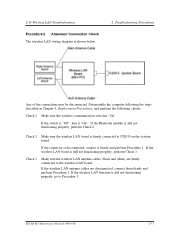
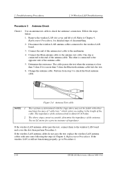
...wireless LAN board is still not functioning properly, perform Check 2. If the wireless LAN antenna cables are firmly connected to Procedure 3. TECRA M1 Maintenance Manual (960 -436) 2-55 2.14 Wireless LAN Troubleshooting Procedure 2 Antennas' Connection Check The wireless LAN wiring diagram is ...". Check 2 Make sure the wireless LAN board is shown below: 2 Troubleshooting Procedures Any of the connections may be disconnected. Disassemble the computer following the steps described in Chapter 4, Replacement Procedures, and perform the following checks: Check 1 Make sure the wireless...
...wireless LAN board is still not functioning properly, perform Check 2. If the wireless LAN antenna cables are firmly connected to Procedure 3. TECRA M1 Maintenance Manual (960 -436) 2-55 2.14 Wireless LAN Troubleshooting Procedure 2 Antennas' Connection Check The wireless LAN wiring diagram is ...". Check 2 Make sure the wireless LAN board is shown below: 2 Troubleshooting Procedures Any of the connections may be disconnected. Disassemble the computer following the steps described in Chapter 4, Replacement Procedures, and perform the following checks: Check 1 Make sure the wireless...
Maintenance Manual
Page 116
... test when the resistance is connected to the length of impedance. The resistances determined with the steps above steps cannot accurately determine the impedance of disassembling. 2. The above may not be stable with new ones following the steps in Chapter 4, Replacement Procedures. Use an LC meter for detailed steps of the... Check Check 1 Use an antenna test cable to the wireless LAN board and cover the slot, then perform Procedure 1. Perform from step 3 to Procedure 4. 2-56 TECRA M1 Maintenance Manual (960 -436)
... test when the resistance is connected to the length of impedance. The resistances determined with the steps above steps cannot accurately determine the impedance of disassembling. 2. The above may not be stable with new ones following the steps in Chapter 4, Replacement Procedures. Use an LC meter for detailed steps of the... Check Check 1 Use an antenna test cable to the wireless LAN board and cover the slot, then perform Procedure 1. Perform from step 3 to Procedure 4. 2-56 TECRA M1 Maintenance Manual (960 -436)
Maintenance Manual
Page 117
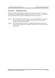
... to Chapter 4, Replacement Procedures, for instruc tions on how to the circuits. TECRA M1 Maintenance Manual (960 -436) 2-57 2.14 Wireless LAN Troubleshooting 2 Troubleshooting Procedures Procedure 4 Replacement Check The wireless LAN board, and the system board are connected to disassemble the computer and then perform the following the instructions in Chapter 4, Replacement Procedures...
... to Chapter 4, Replacement Procedures, for instruc tions on how to the circuits. TECRA M1 Maintenance Manual (960 -436) 2-57 2.14 Wireless LAN Troubleshooting 2 Troubleshooting Procedures Procedure 4 Replacement Check The wireless LAN board, and the system board are connected to disassemble the computer and then perform the following the instructions in Chapter 4, Replacement Procedures...
Maintenance Manual
Page 119
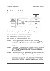
...perform Check 3. Go to Procedure 3. Check 3 If the microphone function does not work properly, the headphone cable may be disconnected. TECRA M1 Maintenance Manual (960 -436) 2-59 If the microphone is still not functioning properly, go to Procedure 3. If the microphone does ...Procedure 2 Connector Check The sound function wiring diagram is shown below: 2 Troubleshooting Procedures Any of the connections may be disconnected. Disassemble the computer following the steps described in Chapter 4, Replacement Procedures and perform the following checks: If the stereo speakers do not ...
...perform Check 3. Go to Procedure 3. Check 3 If the microphone function does not work properly, the headphone cable may be disconnected. TECRA M1 Maintenance Manual (960 -436) 2-59 If the microphone is still not functioning properly, go to Procedure 3. If the microphone does ...Procedure 2 Connector Check The sound function wiring diagram is shown below: 2 Troubleshooting Procedures Any of the connections may be disconnected. Disassemble the computer following the steps described in Chapter 4, Replacement Procedures and perform the following checks: If the stereo speakers do not ...
Maintenance Manual
Page 228
... SD card 4-14 Removing the HDD cover 4-16 Removing the HDD pack 4-17 Removing the HDD bracket 4-18 Removing the Slim select bay module 4-21 Disassembling the Slim select bay module 4-22 Removing the Modem daughter card cover 4-24 Removing the Modem daughter card 4-25 Removing the CPU cover 4-27 Removing... 4-42 Removing the Wireless LAN card cover 4-44 Removing the Wireless LAN card 4-45 Removing the Bluetooth module 4-48 Removing the Display assembly (1 4-49 4-iv TECRA M1 Maintenance Manual (960-436)
... SD card 4-14 Removing the HDD cover 4-16 Removing the HDD pack 4-17 Removing the HDD bracket 4-18 Removing the Slim select bay module 4-21 Disassembling the Slim select bay module 4-22 Removing the Modem daughter card cover 4-24 Removing the Modem daughter card 4-25 Removing the CPU cover 4-27 Removing... 4-42 Removing the Wireless LAN card cover 4-44 Removing the Wireless LAN card 4-45 Removing the Bluetooth module 4-48 Removing the Display assembly (1 4-49 4-iv TECRA M1 Maintenance Manual (960-436)


