
Maintenance Manual
Page 3
...Tecra A3/S2 Maintenance Manual iii NOTE Note" contains general information that could result in property damage if the safety instruction is not observed. If a screw is not fully fastened, it could come loose, creating a danger of a short circuit, which could result in safety hazards. CAUTION: ... Toshiba........."Warning" indicates the existence of a hazard that could cause overheating, smoke or fire. Improper repair of the wrong battery can cause the battery to explode. Installation of the computer may result in bodily injury if the safety instruction is not observed. "Caution"...
...Tecra A3/S2 Maintenance Manual iii NOTE Note" contains general information that could result in property damage if the safety instruction is not observed. If a screw is not fully fastened, it could come loose, creating a danger of a short circuit, which could result in safety hazards. CAUTION: ... Toshiba........."Warning" indicates the existence of a hazard that could cause overheating, smoke or fire. Improper repair of the wrong battery can cause the battery to explode. Installation of the computer may result in bodily injury if the safety instruction is not observed. "Caution"...

Maintenance Manual
Page 6
... Troubleshooting 2-23 2.10 Speaker Troubleshooting 2-25 2.11 Modem Troubleshooting 2-27 2.12 PCMCIA Troubleshooting 2-29 2.13 IEEE 1394 Troubleshooting 2-31 2.14 Wireless LAN Troubleshooting 2-33 vi Tecra A3/S2 Maintenance Manual Bookmark not defined. 2.2 Troubleshooting Flowchart Error! Table of Contents Chapter 1 Hardware Overview 1.1 Features ...1-1 1.2 System Unit ...1-5 1.3 2.5-inch Hard Disk Drive 1-9 1.4 Removable Drives ...1-10...
... Troubleshooting 2-23 2.10 Speaker Troubleshooting 2-25 2.11 Modem Troubleshooting 2-27 2.12 PCMCIA Troubleshooting 2-29 2.13 IEEE 1394 Troubleshooting 2-31 2.14 Wireless LAN Troubleshooting 2-33 vi Tecra A3/S2 Maintenance Manual Bookmark not defined. 2.2 Troubleshooting Flowchart Error! Table of Contents Chapter 1 Hardware Overview 1.1 Features ...1-1 1.2 System Unit ...1-5 1.3 2.5-inch Hard Disk Drive 1-9 1.4 Removable Drives ...1-10...
Maintenance Manual
Page 7
... 3.14 LCD Pixels Mode Test Error! Bookmark not defined. 3.17 LAN Test Error! Bookmark not defined. 3.18 RTC Test Error! Tecra A3/S2 Maintenance Manual vii Bookmark not defined. 3.3 Config Check Test Error! Bookmark not defined. 3.5 PIO Loopback Test Error! Bookmark not defined... Error! Bookmark not defined. 3.16 HDD R/W Test Error! Bookmark not defined. 3.4 DMI Check Test Error! Bookmark not defined. 3.9 Main Battery Charge Test Error! Bookmark not defined. 3.13 Mouse (Pad) Test Error! Bookmark not defined. 3.11 CD-ROM Test Error! Bookmark not defined...
... 3.14 LCD Pixels Mode Test Error! Bookmark not defined. 3.17 LAN Test Error! Bookmark not defined. 3.18 RTC Test Error! Tecra A3/S2 Maintenance Manual vii Bookmark not defined. 3.3 Config Check Test Error! Bookmark not defined. 3.5 PIO Loopback Test Error! Bookmark not defined... Error! Bookmark not defined. 3.16 HDD R/W Test Error! Bookmark not defined. 3.4 DMI Check Test Error! Bookmark not defined. 3.9 Main Battery Charge Test Error! Bookmark not defined. 3.13 Mouse (Pad) Test Error! Bookmark not defined. 3.11 CD-ROM Test Error! Bookmark not defined...
Maintenance Manual
Page 8
Chapter 4 Replacement Procedures 4.1 General ...4-1 4.2 Battery ...4-7 4.3 PC Card ...4-8 4.4 HDD ...4-9 4.5 Optical Drive Module...4-12 4.6 Optical Drive ...4-13 4.7 Wireless LAN...4-15 4.8 Expansion Memory ...4-17 4.9 Keyboard ...4-21 4.10 Bluetooth ...4-21 4.11 Modem...4-25 4.12 Display Assembly...4-26 4.13 Top Cover...4-28 4.14 Touch Pad...4-31 4.15 Speakers...4-32 4.16 System Board ...4-33 4.17 Direct Play buttom board 4-36 4.18 Fan, Hest & CPU...4-37 4.19 Display Mask...4-38 4.20 LCD Module...4-42 4.21 FL Inverter Board...4-44 viii Tecra A3/S2 Maintenance Manual
Chapter 4 Replacement Procedures 4.1 General ...4-1 4.2 Battery ...4-7 4.3 PC Card ...4-8 4.4 HDD ...4-9 4.5 Optical Drive Module...4-12 4.6 Optical Drive ...4-13 4.7 Wireless LAN...4-15 4.8 Expansion Memory ...4-17 4.9 Keyboard ...4-21 4.10 Bluetooth ...4-21 4.11 Modem...4-25 4.12 Display Assembly...4-26 4.13 Top Cover...4-28 4.14 Touch Pad...4-31 4.15 Speakers...4-32 4.16 System Board ...4-33 4.17 Direct Play buttom board 4-36 4.18 Fan, Hest & CPU...4-37 4.19 Display Mask...4-38 4.20 LCD Module...4-42 4.21 FL Inverter Board...4-44 viii Tecra A3/S2 Maintenance Manual

Maintenance Manual
Page 12
Chapter 1 Contents 1 Hardware Overview 1.1 Features ...1-5 1.2 System Unit...1-10 1.3 2.5-inch Hard Disk Drive 1-14 1.4 Removable Drives...1-15 1.4.1 DVD-R/-RW Drive Error! Bookmark not defined. 1.4.2 DVD-ROM Drive 1-15 1.4.3 CD-ROM Drive 1-15 1.4.4 DVD±R/±RW Drive 1-15 1.4.5 DVD Super Multi Drive 1-17 1.5 Power Supply ...1-15 1.6 Batteries ...1-21 1.6.1 Main Battery 1-21 1.6.2 RTC battery 1-22 Tecra A3/S2 Series Maintenance Manual 1-iii
Chapter 1 Contents 1 Hardware Overview 1.1 Features ...1-5 1.2 System Unit...1-10 1.3 2.5-inch Hard Disk Drive 1-14 1.4 Removable Drives...1-15 1.4.1 DVD-R/-RW Drive Error! Bookmark not defined. 1.4.2 DVD-ROM Drive 1-15 1.4.3 CD-ROM Drive 1-15 1.4.4 DVD±R/±RW Drive 1-15 1.4.5 DVD Super Multi Drive 1-17 1.5 Power Supply ...1-15 1.6 Batteries ...1-21 1.6.1 Main Battery 1-21 1.6.2 RTC battery 1-22 Tecra A3/S2 Series Maintenance Manual 1-iii
Maintenance Manual
Page 15
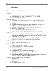
...module/802.11b+g Wireless LAN module) • MDC Modem • Bluetooth modem • Dual-Band build in Antenna for Wireless LAN Communication. 1-6 Tecra A3/S2 Series Maintenance Manual 1 Hardware Overview 1.2 System Unit ‰ BIOS • 1MB Flash ROM for system control. c) Various hot key for ... protection (System). d) Refreshable e) ACPI compliant BIOS ‰ Power • 12-cell Li-Ion smart battery pack with 10.8V*8600mAh capacity or 6-cell Li-Ion smart battery pack with 10.8V*4300mAh capacity (depending on the models). • Approximately 12 hours or longer charge ...
...module/802.11b+g Wireless LAN module) • MDC Modem • Bluetooth modem • Dual-Band build in Antenna for Wireless LAN Communication. 1-6 Tecra A3/S2 Series Maintenance Manual 1 Hardware Overview 1.2 System Unit ‰ BIOS • 1MB Flash ROM for system control. c) Various hot key for ... protection (System). d) Refreshable e) ACPI compliant BIOS ‰ Power • 12-cell Li-Ion smart battery pack with 10.8V*8600mAh capacity or 6-cell Li-Ion smart battery pack with 10.8V*4300mAh capacity (depending on the models). • Approximately 12 hours or longer charge ...
Maintenance Manual
Page 19
...8226; Intel 915PM (Alviso-PM)/ Intel 915GM (Alviso-GM) (400/533 MHz FSB supported) • ICH6-M • ENE KB910 for Keyboard Controller, Battery management Unit, and RTC. • TI PCI7411 for Card Bus PCMCIA, 1394, 5 in 1 controller. • Integrated VGA solution for 915GM/ External VGA... On board with LPC Interface • PC99a, PC2001 • ACPI 2.0 Compliant • Serial Ports • One Full Function Serial Port 1-10 Tecra A3/S2 Series Maintenance Manual Maximum up to 112MHZ per channel. ‰ SMsC LPC 47N217 Super I/O with two 200-pin +2.5V SO-DIMM connector, supporting...
...8226; Intel 915PM (Alviso-PM)/ Intel 915GM (Alviso-GM) (400/533 MHz FSB supported) • ICH6-M • ENE KB910 for Keyboard Controller, Battery management Unit, and RTC. • TI PCI7411 for Card Bus PCMCIA, 1394, 5 in 1 controller. • Integrated VGA solution for 915GM/ External VGA... On board with LPC Interface • PC99a, PC2001 • ACPI 2.0 Compliant • Serial Ports • One Full Function Serial Port 1-10 Tecra A3/S2 Series Maintenance Manual Maximum up to 112MHZ per channel. ‰ SMsC LPC 47N217 Super I/O with two 200-pin +2.5V SO-DIMM connector, supporting...
Maintenance Manual
Page 20
Tecra A3/S2 Series Maintenance Manual 1-11 EPP 1.7 and EPP 1.9 (IEEE 1284 Compliant) • IEEE 1284 Compliant Enhanced Capabilities Port (ECP) • ChiProtect Circuitry for Optimizing Speaker ... for PCI Systems • PCI CLKRUN# Support • Power Management Event(IO_PME#)Interface Pin ‰ Keyboard controller • KB910L is use as keyboard controller and battery management unit ‰ Audio subsystem Realtek ALC250VD for AC97 codec • Support of S'PDIF out is fully compliant with AC97 rev2.3 specification. • 20-bit...
Tecra A3/S2 Series Maintenance Manual 1-11 EPP 1.7 and EPP 1.9 (IEEE 1284 Compliant) • IEEE 1284 Compliant Enhanced Capabilities Port (ECP) • ChiProtect Circuitry for Optimizing Speaker ... for PCI Systems • PCI CLKRUN# Support • Power Management Event(IO_PME#)Interface Pin ‰ Keyboard controller • KB910L is use as keyboard controller and battery management unit ‰ Audio subsystem Realtek ALC250VD for AC97 codec • Support of S'PDIF out is fully compliant with AC97 rev2.3 specification. • 20-bit...
Maintenance Manual
Page 28
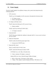
... The EC monitors the following by A/D converted values: • Battery installed The EC checks the following input signal status: • System power ON/OFF status 5. Beep and LED control Beep is low. Tecra A3/S2 Series Maintenance Manual 1-19 1.5 Power Supply 1 Hardware Overview ...1.5 Power Supply The power supply supplies seven different voltages to determine the following values: • AC adaptor current • Battery and temperature 2. Abnormal check The EC...
... The EC monitors the following by A/D converted values: • Battery installed The EC checks the following input signal status: • System power ON/OFF status 5. Beep and LED control Beep is low. Tecra A3/S2 Series Maintenance Manual 1-19 1.5 Power Supply 1 Hardware Overview ...1.5 Power Supply The power supply supplies seven different voltages to determine the following values: • AC adaptor current • Battery and temperature 2. Abnormal check The EC...

Maintenance Manual
Page 29
... gauge. • LB10M= The system will be driven by the battery for 12 more minutes. • LB0 = The battery won't be able to read information of full charge 8. Battery capacity calculation The EC reads battery remaining and percentage capacity from the battery through SMBus. 1-20 Tecra A3/S2 Series Maintenance Manual Power ON/OFF sequence When power...
... gauge. • LB10M= The system will be driven by the battery for 12 more minutes. • LB0 = The battery won't be able to read information of full charge 8. Battery capacity calculation The EC reads battery remaining and percentage capacity from the battery through SMBus. 1-20 Tecra A3/S2 Series Maintenance Manual Power ON/OFF sequence When power...
Maintenance Manual
Page 30
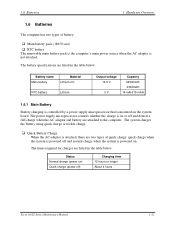
... charges are attached to the computer. The system charges the battery using quick charge or trickle charge. ‰ Quick Battery Charge When the AC adaptor is powered off ) Charging time 12 hours or longer About 4 hours Tecra A3/S2 Series Maintenance Manual 1-21 1.6 Batteries 1 Hardware Overview 1.6 Batteries The computer has two types of quick charge: quick...
... charges are attached to the computer. The system charges the battery using quick charge or trickle charge. ‰ Quick Battery Charge When the AC adaptor is powered off ) Charging time 12 hours or longer About 4 hours Tecra A3/S2 Series Maintenance Manual 1-21 1.6 Batteries 1 Hardware Overview 1.6 Batteries The computer has two types of quick charge: quick...
Maintenance Manual
Page 31
... is powered on ) Data preservation period (full charge) Time About 24 hours 1 month 1-22 Tecra A3/S2 Series Maintenance Manual The AC adaptor or battery is abnormal. 5. The battery becomes fully charged. 2. The battery cell is charging. 1.6.2 RTC battery The RTC battery provides power to explode. The table below lists the charging time and data preservation period...
... is powered on ) Data preservation period (full charge) Time About 24 hours 1 month 1-22 Tecra A3/S2 Series Maintenance Manual The AC adaptor or battery is abnormal. 5. The battery becomes fully charged. 2. The battery cell is charging. 1.6.2 RTC battery The RTC battery provides power to explode. The table below lists the charging time and data preservation period...
Maintenance Manual
Page 35
... Optical drive troubleshooting process 2-27 Modem troubleshooting process 2-30 PCMCIA troubleshooting process 2-32 IEEE 1394 troubleshooting process 2-34 Wireless LAN troubleshooting process 2-36 Tables Table 2-1 Battery LED ...2-8 Table 2-2 DC-IN LED ...2-9 2-iv Tecra A3/S2 Series Maintenance Manual
... Optical drive troubleshooting process 2-27 Modem troubleshooting process 2-30 PCMCIA troubleshooting process 2-32 IEEE 1394 troubleshooting process 2-34 Wireless LAN troubleshooting process 2-36 Tables Table 2-1 Battery LED ...2-8 Table 2-2 DC-IN LED ...2-9 2-iv Tecra A3/S2 Series Maintenance Manual
Maintenance Manual
Page 38
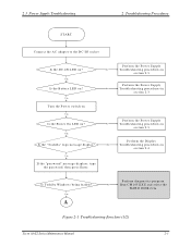
... C-IN socket Is the DC-IN LED on ? Is Toshiba W indow s being loaded? Y es A Perform diagnostics program . No R un C M 165.EX E and select the H ARD D ISK item . Figure 2-1 Troubleshooting flowchart (1/2) Tecra A3/S2 Series Maintenance Manual 2-3 Y es Perform the Pow er ...Supply No Troubleshooting procedures in section 2.4 Y es If the "passw ord" m essage displays, type the passw ord, then press Enter. Y es Is the Battery LED on?
... C-IN socket Is the DC-IN LED on ? Is Toshiba W indow s being loaded? Y es A Perform diagnostics program . No R un C M 165.EX E and select the H ARD D ISK item . Figure 2-1 Troubleshooting flowchart (1/2) Tecra A3/S2 Series Maintenance Manual 2-3 Y es Perform the Pow er ...Supply No Troubleshooting procedures in section 2.4 Y es If the "passw ord" m essage displays, type the passw ord, then press Enter. Y es Is the Battery LED on?

Maintenance Manual
Page 40
...2.4. 3. When a problem has been located, perform the appropriate troubleshooting procedures as follows: 1. The test program should be intermittent. Tecra A3/S2 Series Maintenance Manual 2-5 If an error is detected by the printer (parallel) port test, perform the Printer Port Troubleshooting procedures...is detected by the keyboard test, perform the Keyboard Troubleshooting procedures in Section 2.3. 2. If an error is detected by the battery test, perform the Power Supply Troubleshooting procedures in Section 2.5. 4. If an error is detected by the TouchPad test, perform ...
...2.4. 3. When a problem has been located, perform the appropriate troubleshooting procedures as follows: 1. The test program should be intermittent. Tecra A3/S2 Series Maintenance Manual 2-5 If an error is detected by the printer (parallel) port test, perform the Printer Port Troubleshooting procedures...is detected by the keyboard test, perform the Keyboard Troubleshooting procedures in Section 2.3. 2. If an error is detected by the battery test, perform the Power Supply Troubleshooting procedures in Section 2.5. 4. If an error is detected by the TouchPad test, perform ...
Maintenance Manual
Page 42
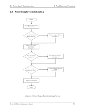
2.3 Power Supply Troubleshooting 2.3 Power Supply Troubleshooting START Check Power Supply Status (Procedure 1) 2 Troubleshooting Procedures Are the DC-IN and Battery LEDs lit? Y es Check power supply connections (Procedure 3) No Replace adaptor / battery (Procedure 2) Can you turn the computer on? No Are the internal power connections secure? Y es Replace system board Y es Run diagnostic program (Procedure 4) Perform internal connection No check (Procedure 5) END Figure 2-2 Power Supply Troubleshooting Process Tecra A3/S2 Series Maintenance Manual 2-7
2.3 Power Supply Troubleshooting 2.3 Power Supply Troubleshooting START Check Power Supply Status (Procedure 1) 2 Troubleshooting Procedures Are the DC-IN and Battery LEDs lit? Y es Check power supply connections (Procedure 3) No Replace adaptor / battery (Procedure 2) Can you turn the computer on? No Are the internal power connections secure? Y es Replace system board Y es Run diagnostic program (Procedure 4) Perform internal connection No check (Procedure 5) END Figure 2-2 Power Supply Troubleshooting Process Tecra A3/S2 Series Maintenance Manual 2-7
Maintenance Manual
Page 43
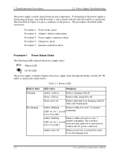
...Battery not in discharging state 2-8 Tecra A3/S2 Series Maintenance Manual Table 2-1 Battery LED Battery State Charging Discharging LED colors Definition Amber, solid on Battery charging with AC (Bad cell/ Overheated) Amber, blinking Battery within critical low state: 3 (LED on without the AC power connected. Amber color off Battery...process. The flowchart in this section are: Procedure 1: Power status check Procedure 2: Adaptor / battery replacement Procedure 3: Power supply connection check Procedure 4: Diagnostic check Procedure 5: Internal connection check Procedure...
...Battery not in discharging state 2-8 Tecra A3/S2 Series Maintenance Manual Table 2-1 Battery LED Battery State Charging Discharging LED colors Definition Amber, solid on Battery charging with AC (Bad cell/ Overheated) Amber, blinking Battery within critical low state: 3 (LED on without the AC power connected. Amber color off Battery...process. The flowchart in this section are: Procedure 1: Power status check Procedure 2: Adaptor / battery replacement Procedure 3: Power supply connection check Procedure 4: Diagnostic check Procedure 5: Internal connection check Procedure...
Maintenance Manual
Page 44
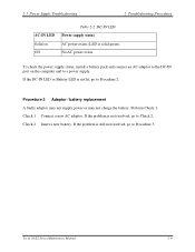
...exists (LED is not resolved, go to Procedure 2. Perform Check 1. If the problem is solid green). If the DC-IN LED or Battery LED is still not resolved, go to Procedure 3. 2.3 Power Supply Troubleshooting 2 Troubleshooting Procedures AC-IN LED Solid on the computer and to... a power supply. Procedure 2 Adaptor / battery replacement A faulty adaptor may not supply power or may not charge the battery. If the problem is not lit, go to Check 2. Check 1 Connect a new AC adaptor. Check 2 Insert a new battery. Tecra A3/S2 Series Maintenance Manual 2-9 No AC power exists....
...exists (LED is not resolved, go to Procedure 2. Perform Check 1. If the problem is solid green). If the DC-IN LED or Battery LED is still not resolved, go to Procedure 3. 2.3 Power Supply Troubleshooting 2 Troubleshooting Procedures AC-IN LED Solid on the computer and to... a power supply. Procedure 2 Adaptor / battery replacement A faulty adaptor may not supply power or may not charge the battery. If the problem is not lit, go to Check 2. Check 1 Connect a new AC adaptor. Check 2 Insert a new battery. Tecra A3/S2 Series Maintenance Manual 2-9 No AC power exists....

Maintenance Manual
Page 45
...go to Check 5. Check the power cable for breaks. Check 3 Make sure that the AC adaptor output voltage is properly installed and the battery LED still does not light, go to Check 3. Perform Check 1. If the power cord is shown below: AC power cord AC adaptor... AC adaptor cord System board Battery Any of the computer. • If the DC-IN input socket is loose, go to Procedure 5. • If it is not loose, go to Procedure 4. 2-10 Tecra A3/S2 Series Maintenance Manual 2 Troubleshooting Procedures 2.3 Power Supply Troubleshooting...
...go to Check 5. Check the power cable for breaks. Check 3 Make sure that the AC adaptor output voltage is properly installed and the battery LED still does not light, go to Check 3. Perform Check 1. If the power cord is shown below: AC power cord AC adaptor... AC adaptor cord System board Battery Any of the computer. • If the DC-IN input socket is loose, go to Procedure 5. • If it is not loose, go to Procedure 4. 2-10 Tecra A3/S2 Series Maintenance Manual 2 Troubleshooting Procedures 2.3 Power Supply Troubleshooting...

Maintenance Manual
Page 46
... procedures described in Chapter 4. Replace it is functioning normally. If no problem is detected, the battery is connected firmly, go to Check 3. Check 2 Make sure that the battery cable is firmly connected to make sure that the fuses on the system board are not blown....4 Diagnostic check The power supply may not charge the battery pack. Reinstall the battery pack. 2. Attach the AC adaptor and turn on the power. Run the Diagnostic test following the instructions in Chapter 3, Tests and Diagnostics. Tecra A3/S2 Series Maintenance Manual 2-11 If you cannot turn ...
... procedures described in Chapter 4. Replace it is functioning normally. If no problem is detected, the battery is connected firmly, go to Check 3. Check 2 Make sure that the battery cable is firmly connected to make sure that the fuses on the system board are not blown....4 Diagnostic check The power supply may not charge the battery pack. Reinstall the battery pack. 2. Attach the AC adaptor and turn on the power. Run the Diagnostic test following the instructions in Chapter 3, Tests and Diagnostics. Tecra A3/S2 Series Maintenance Manual 2-11 If you cannot turn ...


