Maintenance Manual
Page 2
... and Windows are registered trademarks of Microsoft Corporation. Super I/O and MICROWIRE are registered trademarks of National Semiconductor Corporation. Toshiba PORTEGE R100 Maintenance Manual First edition March 2003 Disclaimer The information presented in any succeeding product and this manual. However, succeeding ...computers and manuals are registered trademarks of Creative Technology Ltd. ii PORTEGE R100 Maintenance Manual (960-440) Trademarks IBM is a registered trademark, and IBM PC/AT, PS/2, OS/2 and VGA ...
... and Windows are registered trademarks of Microsoft Corporation. Super I/O and MICROWIRE are registered trademarks of National Semiconductor Corporation. Toshiba PORTEGE R100 Maintenance Manual First edition March 2003 Disclaimer The information presented in any succeeding product and this manual. However, succeeding ...computers and manuals are registered trademarks of Creative Technology Ltd. ii PORTEGE R100 Maintenance Manual (960-440) Trademarks IBM is a registered trademark, and IBM PC/AT, PS/2, OS/2 and VGA ...
Maintenance Manual
Page 3
..., if the safety instruction is not observed. If you replace the battery pack or RTC battery, be italicized and identified as PORTEGE R100 in the field. Improper repair of a hazard that relates to fasten screws securely with the ISO/DIS 8764-1:1996. WARNING:... This maintenance manual describes how to perform hardware service maintenance for the Toshiba Personal Computer PORTEGE R100, referred to use only the same model battery or an equivalent battery recommended by Toshiba. Toshiba requires service technicians and authorized dealers or service providers to ensure the ...
..., if the safety instruction is not observed. If you replace the battery pack or RTC battery, be italicized and identified as PORTEGE R100 in the field. Improper repair of a hazard that relates to fasten screws securely with the ISO/DIS 8764-1:1996. WARNING:... This maintenance manual describes how to perform hardware service maintenance for the Toshiba Personal Computer PORTEGE R100, referred to use only the same model battery or an equivalent battery recommended by Toshiba. Toshiba requires service technicians and authorized dealers or service providers to ensure the ...
Maintenance Manual
Page 21
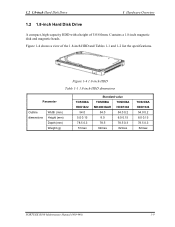
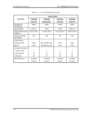
... HDD Table 1-1 1.8-inch HDD dimensions Parameter Outline dimensions Width (mm) Height (mm) Depth (mm) Weight (g) TOSHIBA HDD1422 54.0 5.0 0.15 78.5 0.3 51max Standard value TOSHIBA TOSHIBA MK2003GAH HDD1384 54.0 54.0 0.2 8.0 8.0 0.15 78.5 78.5 0.3 62max 62max TOSHIBA HDD1524 54.0 0.2 8.0 0.15 78.5 0.3 62max PORTEGE R100 Maintenance Manual (960-440) 1-9 Contains a 1.8-inch magnetic disk and magnetic heads. 1.2 1.8-inch Hard Disk...
... HDD Table 1-1 1.8-inch HDD dimensions Parameter Outline dimensions Width (mm) Height (mm) Depth (mm) Weight (g) TOSHIBA HDD1422 54.0 5.0 0.15 78.5 0.3 51max Standard value TOSHIBA TOSHIBA MK2003GAH HDD1384 54.0 54.0 0.2 8.0 8.0 0.15 78.5 78.5 0.3 62max 62max TOSHIBA HDD1524 54.0 0.2 8.0 0.15 78.5 0.3 62max PORTEGE R100 Maintenance Manual (960-440) 1-9 Contains a 1.8-inch magnetic disk and magnetic heads. 1.2 1.8-inch Hard Disk...
Maintenance Manual
Page 22
... Overview 1.2 1.8-inch Hard Disk Drive Table 1-2 1.8-inch HDD Specifications Parameter TOSHIBA HDD1422 Storage size (formatted) 20GB Speed (RPM) 4,200 0.1 Data transfer...msec) Track to track 3 Average time 15 Max seek 26 Start time (sec) 3.5 typical 20 max Specification TOSHIBA TOSHIBA MK2003GAH HDD1384 20GB 30GB 4,200 115.6 to 204.4 4,200 114.8 to 222.7 100 100 2237 (56....15 26 3.5 typical 20 max 3 15 26 3.5 typical 20 max TOSHIBA HDD1524 40GB 4,200 0.1 125.5 to 253.1 100 3465 27.4K 3 15 26 3.5 typical 20 max 1-10 PORTEGE R100 Maintenance Manual (960-440)
... Overview 1.2 1.8-inch Hard Disk Drive Table 1-2 1.8-inch HDD Specifications Parameter TOSHIBA HDD1422 Storage size (formatted) 20GB Speed (RPM) 4,200 0.1 Data transfer...msec) Track to track 3 Average time 15 Max seek 26 Start time (sec) 3.5 typical 20 max Specification TOSHIBA TOSHIBA MK2003GAH HDD1384 20GB 30GB 4,200 115.6 to 204.4 4,200 114.8 to 222.7 100 100 2237 (56....15 26 3.5 typical 20 max 3 15 26 3.5 typical 20 max TOSHIBA HDD1524 40GB 4,200 0.1 125.5 to 253.1 100 3465 27.4K 3 15 26 3.5 typical 20 max 1-10 PORTEGE R100 Maintenance Manual (960-440)
Maintenance Manual
Page 37
...Chapter 3. Cleaning disk kit (for PC card 9. Wraparound connector for FDD head cleaning) 6. Microphone 15. LAN wraparound connector PORTEGE R100 Maintenance Manual (960-440) 2-1 Sound 11. Test Program operations are necessary for implementing the Diagnostics procedures: 1. Diagnostics Disk ...1.8" HDD 5. Display 7. A set of tools for maintenance) 2. Headphone 14. Tester 10. PC with the ISO/DIS 8764-1:1996. 3. Toshiba MS-DOS system FD 4. External USB mouse 13. Keyboard 6. Modem 9. SD card slot 12. Work disk (for displaying debug port test result) ...
...Chapter 3. Cleaning disk kit (for PC card 9. Wraparound connector for FDD head cleaning) 6. Microphone 15. LAN wraparound connector PORTEGE R100 Maintenance Manual (960-440) 2-1 Sound 11. Test Program operations are necessary for implementing the Diagnostics procedures: 1. Diagnostics Disk ...1.8" HDD 5. Display 7. A set of tools for maintenance) 2. Headphone 14. Tester 10. PC with the ISO/DIS 8764-1:1996. 3. Toshiba MS-DOS system FD 4. External USB mouse 13. Keyboard 6. Modem 9. SD card slot 12. Work disk (for displaying debug port test result) ...
Maintenance Manual
Page 39
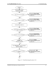
...? No Perform the Display Troubleshooting Procedures in section 2.4. No Is the "Toshiba" logo message displayed? Yes Perform the System Board Troubleshooting Procedures in section 2.8. Does the DC IN icon glow? Yes Turn the Power Switch on ? Yes 1 Figure 2-1 Troubleshooting flowchart (1/2) PORTEGE R100 Maintenance Manual (960-440) 2-3 Yes Does the Battery icon glow? No...
...? No Perform the Display Troubleshooting Procedures in section 2.4. No Is the "Toshiba" logo message displayed? Yes Perform the System Board Troubleshooting Procedures in section 2.8. Does the DC IN icon glow? Yes Turn the Power Switch on ? Yes 1 Figure 2-1 Troubleshooting flowchart (1/2) PORTEGE R100 Maintenance Manual (960-440) 2-3 Yes Does the Battery icon glow? No...
Maintenance Manual
Page 67
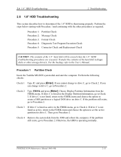
... Procedure 2. Procedure 1 Partition Check Insert the Toshiba MS-DOS system disk and start the computer. If you can change to drive C, go to Check 2. Check 3 If drive C is not listed as active, return to the FDISK menu and choose the option to the User's Manual. PORTEGE R100 Maintenance Manual (960-440) 2-31 Perform...
... Procedure 2. Procedure 1 Partition Check Insert the Toshiba MS-DOS system disk and start the computer. If you can change to drive C, go to Check 2. Check 3 If drive C is not listed as active, return to the FDISK menu and choose the option to the User's Manual. PORTEGE R100 Maintenance Manual (960-440) 2-31 Perform...
Maintenance Manual
Page 93
... To start the DIAGNOSTIC PROGRAM, follow these steps: 1. The following menu will appear: TOSHIBA personal computer XXXX DIAGNOSTICS version X.XX (c) copyright TOSHIBA Corp. 20XX DIAGNOSTICS MENU : 1 - If a test program is in progress, press [Ctrl] + [C] to exit the test program. PORTEGE R100 Maintenance Manual (960-440) 3-3 HEAD CLEANING 5 - HARD DISK FORMAT 3 4 - Insert the test program...
... To start the DIAGNOSTIC PROGRAM, follow these steps: 1. The following menu will appear: TOSHIBA personal computer XXXX DIAGNOSTICS version X.XX (c) copyright TOSHIBA Corp. 20XX DIAGNOSTICS MENU : 1 - If a test program is in progress, press [Ctrl] + [C] to exit the test program. PORTEGE R100 Maintenance Manual (960-440) 3-3 HEAD CLEANING 5 - HARD DISK FORMAT 3 4 - Insert the test program...
Maintenance Manual
Page 94
The following TEST MENU will appear: TOSHIBA personal computer XXXX DIAGNOSTICS Version X.XX (c) copyright TOSHIBA Corp. 20XX DIAGNOSTIC TEST MENU : 1 - EXPANSION TEST 12 13 - 14 - 88 - ERROR RETRY COUNT SET [FDD & HDD] 99 - EXIT TO DIAGNOSTICS MENU Functions...Enter. SYSTEM TEST 2 - HARD DISK TEST 9 - 3 Tests and Diagnostics 3.2 Executing the Diagnostic Test 3. Set the highlight bar to Function 99 and press Enter. 3-4 PORTEGE R100 Maintenance Manual (960-440) DISPLAY TEST 5 - REAL TIMER TEST 10 - NDP TEST 11 - Function 88 sets the floppy disk drive and hard disk drive error...
The following TEST MENU will appear: TOSHIBA personal computer XXXX DIAGNOSTICS Version X.XX (c) copyright TOSHIBA Corp. 20XX DIAGNOSTIC TEST MENU : 1 - EXPANSION TEST 12 13 - 14 - 88 - ERROR RETRY COUNT SET [FDD & HDD] 99 - EXIT TO DIAGNOSTICS MENU Functions...Enter. SYSTEM TEST 2 - HARD DISK TEST 9 - 3 Tests and Diagnostics 3.2 Executing the Diagnostic Test 3. Set the highlight bar to Function 99 and press Enter. 3-4 PORTEGE R100 Maintenance Manual (960-440) DISPLAY TEST 5 - REAL TIMER TEST 10 - NDP TEST 11 - Function 88 sets the floppy disk drive and hard disk drive error...
Maintenance Manual
Page 121
... & Receive test [Initiator] * * * ....Press test number [1-2,0] ?1 ======== RESPONDER SET ======== ORiWL.EXE Rev.03 Copyright (c) Toshiba Corporation,2000, 2001 Initializing... [[[ Responder Mode ]]] MAC address : XXXXXXXXXXXX Ad-hoc mode SS ID : PHN Test Channel : 10 Tx ratio : 2 Mbp PASS : 134 ERROR : 0 PORTEGE R100 Maintenance Manual (960-440) 3-31 The following message will appear: #### Wireless LAN sub...
... & Receive test [Initiator] * * * ....Press test number [1-2,0] ?1 ======== RESPONDER SET ======== ORiWL.EXE Rev.03 Copyright (c) Toshiba Corporation,2000, 2001 Initializing... [[[ Responder Mode ]]] MAC address : XXXXXXXXXXXX Ad-hoc mode SS ID : PHN Test Channel : 10 Tx ratio : 2 Mbp PASS : 134 ERROR : 0 PORTEGE R100 Maintenance Manual (960-440) 3-31 The following message will appear: #### Wireless LAN sub...
Maintenance Manual
Page 122
... test [Initiator] * * * ....Press test number [1-2,0] ?1 ======== RESPONDER SET ======== ORiWL.EXE Rev.03 Copyright (c) Toshiba Corporation,2000, 2001 Initializing... [[[ Responder Mode ]]] MAC address : XXXXXXXXXXXX Ad-hoc mode SS ID : PHN Test Channel : 10 Tx ratio : 2 Mbps PASS : 134 ERROR : 0 3-32 PORTEGE R100 Maintenance Manual (960-440) The Wireless LAN test menu will appear in the...
... test [Initiator] * * * ....Press test number [1-2,0] ?1 ======== RESPONDER SET ======== ORiWL.EXE Rev.03 Copyright (c) Toshiba Corporation,2000, 2001 Initializing... [[[ Responder Mode ]]] MAC address : XXXXXXXXXXXX Ad-hoc mode SS ID : PHN Test Channel : 10 Tx ratio : 2 Mbps PASS : 134 ERROR : 0 3-32 PORTEGE R100 Maintenance Manual (960-440) The Wireless LAN test menu will appear in the...
Maintenance Manual
Page 123
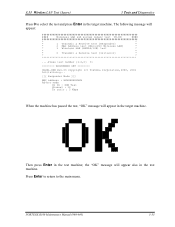
...Mini-PCI Wireless LAN] * * 3 Wireless LAN (WEP64/128) test * * * * 0 Transmit & Receive test [Initiator] * * * ....Press test number [1-2,0] ?1 ======== RESPONDER SET ======== ORiWL.EXE Rev.03 Copyright (c) Toshiba Corporation,2000, 2001 Initializing... [[[ Responder Mode ]]] MAC address : XXXXXXXXXXXX Ad-hoc mode SS ID : PHN Test Channel : 10 Tx ratio : 2 Mbps When the machine has.... 3.13 Wireless LAN Test (Agere) 3 Tests and Diagnostics Press 0 to the main menu. the "OK" message will appear in the test machine; PORTEGE R100 Maintenance Manual (960-440) 3-33
...Mini-PCI Wireless LAN] * * 3 Wireless LAN (WEP64/128) test * * * * 0 Transmit & Receive test [Initiator] * * * ....Press test number [1-2,0] ?1 ======== RESPONDER SET ======== ORiWL.EXE Rev.03 Copyright (c) Toshiba Corporation,2000, 2001 Initializing... [[[ Responder Mode ]]] MAC address : XXXXXXXXXXXX Ad-hoc mode SS ID : PHN Test Channel : 10 Tx ratio : 2 Mbps When the machine has.... 3.13 Wireless LAN Test (Agere) 3 Tests and Diagnostics Press 0 to the main menu. the "OK" message will appear in the test machine; PORTEGE R100 Maintenance Manual (960-440) 3-33
Maintenance Manual
Page 167
4 Replacement Procedures 4.14 System board/FAN 4-34 4.14.1 System board 4-34 4.14.2 FAN 4-36 4.15 LED SW membrane 4-38 4.16 LCD mask/FL inverter/LCD 4-39 4.16.1 LCD mask 4-39 4.16.2 FL inverter 4-41 4.16.3 LCD 4-42 4.17 LCD cable/Wireless LAN cable/Antenna cover 4-43 4.17.1 LCD cable 4-43 4.17.2 Wireless LAN cable/Antenna cover 4-45 4.18 Hinge...4-48 4.19 Fluorescent Lamp 4-50 4.19.1 Replacing the 14.1 inch Toshiba fluorescent lamp 4-51 4-iv PORTEGE R100 Maintenance Manual (960-440)
4 Replacement Procedures 4.14 System board/FAN 4-34 4.14.1 System board 4-34 4.14.2 FAN 4-36 4.15 LED SW membrane 4-38 4.16 LCD mask/FL inverter/LCD 4-39 4.16.1 LCD mask 4-39 4.16.2 FL inverter 4-41 4.16.3 LCD 4-42 4.17 LCD cable/Wireless LAN cable/Antenna cover 4-43 4.17.1 LCD cable 4-43 4.17.2 Wireless LAN cable/Antenna cover 4-45 4.18 Hinge...4-48 4.19 Fluorescent Lamp 4-50 4.19.1 Replacing the 14.1 inch Toshiba fluorescent lamp 4-51 4-iv PORTEGE R100 Maintenance Manual (960-440)
Maintenance Manual
Page 169
... Removing the palm rest cover left side hinge 4-48 Figure 4-39 Removing the palm rest cover right side hinge 4-49 Figure 4-40 to 4-51 Replacing Toshiba fluorescent lamp (1) to (10 4-51 to 4-60 4-vi PORTEGE R100 Maintenance Manual (960-440)
... Removing the palm rest cover left side hinge 4-48 Figure 4-39 Removing the palm rest cover right side hinge 4-49 Figure 4-40 to 4-51 Replacing Toshiba fluorescent lamp (1) to (10 4-51 to 4-60 4-vi PORTEGE R100 Maintenance Manual (960-440)
Maintenance Manual
Page 171
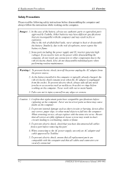
... in fire or explosion. When connecting to the AC power supply, use authentic parts or equivalent parts approved by Toshiba. 5. Danger: 1. Some parts including the power supply and FL inverter generate high voltages. To prevent electric shock... or flame. 3. In the case of the battery, always use only an AC adapter and cable approved by Toshiba. To prevent electric shock, turn on the computer. Take care not to injury yourself on the computer. 2. ... connectors are incompatible with the computer and that are securely connected. 4-2 PORTEGE R100 Maintenance Manual (960-440)
... in fire or explosion. When connecting to the AC power supply, use authentic parts or equivalent parts approved by Toshiba. 5. Danger: 1. Some parts including the power supply and FL inverter generate high voltages. To prevent electric shock... or flame. 3. In the case of the battery, always use only an AC adapter and cable approved by Toshiba. To prevent electric shock, turn on the computer. Take care not to injury yourself on the computer. 2. ... connectors are incompatible with the computer and that are securely connected. 4-2 PORTEGE R100 Maintenance Manual (960-440)
Maintenance Manual
Page 178
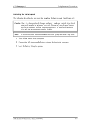
.... 1. Use only the batteries approved by Toshiba. Turn off any dirt with the laws and ordinances of the computer. 2. Connect the AC adapter and all other external devices to the computer. 3. Note: Check visually the battery terminals and clean off the power of your local authority. PORTEGE R100 Maintenance Manual (960-440) 4-9 Inset...
.... 1. Use only the batteries approved by Toshiba. Turn off any dirt with the laws and ordinances of the computer. 2. Connect the AC adapter and all other external devices to the computer. 3. Note: Check visually the battery terminals and clean off the power of your local authority. PORTEGE R100 Maintenance Manual (960-440) 4-9 Inset...
Maintenance Manual
Page 219
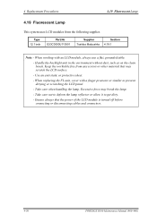
...any screws or other material that the power of the LCD module is turned off before connecting or disconnecting cables and connectors. 4-50 PORTEGE R100 Maintenance Manual (960-440) Handle the backlight unit in the environment without dust, such as on the clean bench. Use an anti...flat, grounded table. - Ensure always that may break the lamp. - Take care when handling the lamp. Type 12.1 inch Part.No G33C0000U110001 Supplier Toshiba Matsushita Section 4.19.1 Note: - Take care not to deform the lamp reflector or allow it to prevent dirtying or scratching the LCD panel. -...
...any screws or other material that the power of the LCD module is turned off before connecting or disconnecting cables and connectors. 4-50 PORTEGE R100 Maintenance Manual (960-440) Handle the backlight unit in the environment without dust, such as on the clean bench. Use an anti...flat, grounded table. - Ensure always that may break the lamp. - Take care when handling the lamp. Type 12.1 inch Part.No G33C0000U110001 Supplier Toshiba Matsushita Section 4.19.1 Note: - Take care not to deform the lamp reflector or allow it to prevent dirtying or scratching the LCD panel. -...
Maintenance Manual
Page 220
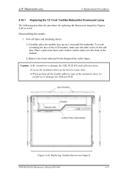
...the table is free of the module. 2) Remove the items indicated by the diagonal line in the figure. Figure 4-40 Replacing Toshiba fluorescent lamp(1) PORTEGE R100 Maintenance Manual (960-440) 4-51 Place a protection sheet (soft cloth or similar item) over the front of dirt and dust.... 4.19 Fluorescent Lamp 4 Replacement Procedures 4.19.1 Replacing the 12.1 Inch Toshiba Matsushita Fluorescent Lamp The following describes the procedure for ...
...the table is free of the module. 2) Remove the items indicated by the diagonal line in the figure. Figure 4-40 Replacing Toshiba fluorescent lamp(1) PORTEGE R100 Maintenance Manual (960-440) 4-51 Place a protection sheet (soft cloth or similar item) over the front of dirt and dust.... 4.19 Fluorescent Lamp 4 Replacement Procedures 4.19.1 Replacing the 12.1 Inch Toshiba Matsushita Fluorescent Lamp The following describes the procedure for ...

Maintenance Manual
Page 221
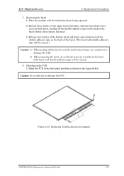
Figure 4-41 Replacing Toshiba fluorescent lamp(2) 4-52 PORTEGE R100 Maintenance Manual (960-440) 4 Replacement Procedures 4.19 Fluorescent Lamp 2. Removing screws 1) Spread out the insulation sheet without detaching from the bezel side, as shown in the figure below. 2) Remove the left side screws and right side screws in the order c shown in the figure below. Caution: Use a Philips screwdriver with type 0 bit to remove the screws.
Figure 4-41 Replacing Toshiba fluorescent lamp(2) 4-52 PORTEGE R100 Maintenance Manual (960-440) 4 Replacement Procedures 4.19 Fluorescent Lamp 2. Removing screws 1) Spread out the insulation sheet without detaching from the bezel side, as shown in the figure below. 2) Remove the left side screws and right side screws in the order c shown in the figure below. Caution: Use a Philips screwdriver with type 0 bit to remove the screws.
Maintenance Manual
Page 222
... the FPC. Caution: Be careful not to the horizontal position as shown in the figure below. 4.19 Fluorescent Lamp 4 Replacement Procedures 3. Figure 4-42 Replacing Toshiba fluorescent lamp(4) PORTEGE R100 Maintenance Manual (960-440) 4-53 Removing the bezel 1) Place the module with double-adhesive tape will be reused.) Caution: 1) When peeling off the double...
... the FPC. Caution: Be careful not to the horizontal position as shown in the figure below. 4.19 Fluorescent Lamp 4 Replacement Procedures 3. Figure 4-42 Replacing Toshiba fluorescent lamp(4) PORTEGE R100 Maintenance Manual (960-440) 4-53 Removing the bezel 1) Place the module with double-adhesive tape will be reused.) Caution: 1) When peeling off the double...


