
Toshiba Online Users Guide for Satellite A20/A25
Page 31
... 218 Keyboard problems 219 Display problems 220 Disk drive problems 222 DVD-ROM or multi-function drive problems.. 224 Sound system problems 225 PC Card problems 226 Printer problems 229 Modem problems 230 Develop good computing habits 230 If you need further assistance 231 Before... you call 232 Contacting Toshiba 232 Other Toshiba Internet Web sites 233 Toshiba's worldwide offices 234 Appendix A: Hot Keys 237 Volume Mute 237...
... 218 Keyboard problems 219 Display problems 220 Disk drive problems 222 DVD-ROM or multi-function drive problems.. 224 Sound system problems 225 PC Card problems 226 Printer problems 229 Modem problems 230 Develop good computing habits 230 If you need further assistance 231 Before... you call 232 Contacting Toshiba 232 Other Toshiba Internet Web sites 233 Toshiba's worldwide offices 234 Appendix A: Hot Keys 237 Volume Mute 237...

Toshiba Online Users Guide for Satellite A20/A25
Page 256
...also called software) are operating system, application, and utility. By volatile, we mean that can be produced on the screen. random access memory - A credit-card-sized expansion card designed to a network or a peripheral device. peripheral - Any device, such as a mouse, that , when followed by the computer's CPU. pixel - ...to increase the capabilities of instructions that can be written to as well as modem, fax/modem, hard disk drive, network adapter, sound card, or SCSI adapter. This type of a file include the file's type, size, and creation date. reboot - read .
...also called software) are operating system, application, and utility. By volatile, we mean that can be produced on the screen. random access memory - A credit-card-sized expansion card designed to a network or a peripheral device. peripheral - Any device, such as a mouse, that , when followed by the computer's CPU. pixel - ...to increase the capabilities of instructions that can be written to as well as modem, fax/modem, hard disk drive, network adapter, sound card, or SCSI adapter. This type of a file include the file's type, size, and creation date. reboot - read .

Toshiba Online Users Guide for Satellite A20/A25
Page 267
267 Index multi-function drive tray does not eject 224 no sound 225 non-system disk or disk error 209, 224 PC Card 226 checklist 227 error occurs 228 hot swapping fails 228 not recognized 228 slot appears dead 227 Plug and Play 214 power and batteries 218 ... start 209 programs closing 150 not running correctly 223 starting 87 Web browsers 178 properties 154 R recording adjusting quality 182 sounds 181 Recycle Bin 137, 157 remaining battery power 126 removing a PC Card 189 CDs and DVDs 99 main battery 129 resizing windows 147, 149 Restart command 103 RTC (real-time clock...
267 Index multi-function drive tray does not eject 224 no sound 225 non-system disk or disk error 209, 224 PC Card 226 checklist 227 error occurs 228 hot swapping fails 228 not recognized 228 slot appears dead 227 Plug and Play 214 power and batteries 218 ... start 209 programs closing 150 not running correctly 223 starting 87 Web browsers 178 properties 154 R recording adjusting quality 182 sounds 181 Recycle Bin 137, 157 remaining battery power 126 removing a PC Card 189 CDs and DVDs 99 main battery 129 resizing windows 147, 149 Restart command 103 RTC (real-time clock...
Toshiba Online Users Guide for Satellite A20/A25
Page 268
... and time 156 printer 76 shortcut creating 151 menu 140 Shut down using 105 Shut down command 103 sound .wav files 181 problem solving 225 speakers external 183 stereo 43 Stand by command 116 Standby low battery...the modem 101 television adjusting display 186 text file 143 toolbars displaying in a window 170 Toshiba Accessories Information 35 Internet Web sites 233 TOSHIBA Console 87, 199 Toshiba Hardware Setup 204 TouchPad disabling or enabling 242 using 139 using with control buttons 139 ...Locator) 165, 178 USB (Universal Serial Bus) port 39 USB mouse connecting 75 using modem 101 PC Cards 188
... and time 156 printer 76 shortcut creating 151 menu 140 Shut down using 105 Shut down command 103 sound .wav files 181 problem solving 225 speakers external 183 stereo 43 Stand by command 116 Standby low battery...the modem 101 television adjusting display 186 text file 143 toolbars displaying in a window 170 Toshiba Accessories Information 35 Internet Web sites 233 TOSHIBA Console 87, 199 Toshiba Hardware Setup 204 TouchPad disabling or enabling 242 using 139 using with control buttons 139 ...Locator) 165, 178 USB (Universal Serial Bus) port 39 USB mouse connecting 75 using modem 101 PC Cards 188
Maintenance Manual
Page 8
2.14 SD Card Troubleshooting 2-59 Chapter 3 Tests and Diagnostics 3.1 The Diagnostic Test...3-1 3.2 Executing the Diagnostic Test 3-3 3.3 Subtest Names...3-7 3.4 System Test...3-9 3.5 Memory Test...3-12 3.6 Keyboard Test...3-14 3.7 Display Test...3-... ...3-32 3.14 Expansion Test...3-34 3.15 CD-ROM/DVD-ROM Test 3-36 3.16 Wireless LAN Test (Agere 3-37 3.17 Wireless LAN Test (Atheros 3-42 3.18 Sound/LAN/Modem Test 3-45 3.19 Error Code and Error Status Names 3-51 3.20 Hard Disk Test Detail Status 3-54 3.21 Head Cleaning ...3-56 3.22 Log...
2.14 SD Card Troubleshooting 2-59 Chapter 3 Tests and Diagnostics 3.1 The Diagnostic Test...3-1 3.2 Executing the Diagnostic Test 3-3 3.3 Subtest Names...3-7 3.4 System Test...3-9 3.5 Memory Test...3-12 3.6 Keyboard Test...3-14 3.7 Display Test...3-... ...3-32 3.14 Expansion Test...3-34 3.15 CD-ROM/DVD-ROM Test 3-36 3.16 Wireless LAN Test (Agere 3-37 3.17 Wireless LAN Test (Atheros 3-42 3.18 Sound/LAN/Modem Test 3-45 3.19 Error Code and Error Status Names 3-51 3.20 Hard Disk Test Detail Status 3-54 3.21 Head Cleaning ...3-56 3.22 Log...

Maintenance Manual
Page 9
...Keyboard ...4-32 4.11 Memory Module...4-36 4.12 Wireless LAN Card 4-38 4.13 Bluetooth...4-41 4.14 Switch Board...4-43 4.15 Top Cover with Display Assembly 4-45 4.16 Touch Pad ...4-48 4.17 Front Membrane ASSY 4-50 4.18 USB Board...4-52 4.19 Sound Board ...4-54 4.20 RTC Battery...4-56 4.21 DC-IN... Jack ...4-58 4.22 System Board ...4-59 4.23 Sub Fan...4-61 4.24 PC Card Slot...4-63 4.25 Speakers ...4-65 4.26 Touch Pad Switch...4-67 4.27 Display Mask...4-68 4.28 FL Inverter ...4-70 4.29 LCD Module ...4-72 Satellite A20 Maintenance Manual...
...Keyboard ...4-32 4.11 Memory Module...4-36 4.12 Wireless LAN Card 4-38 4.13 Bluetooth...4-41 4.14 Switch Board...4-43 4.15 Top Cover with Display Assembly 4-45 4.16 Touch Pad ...4-48 4.17 Front Membrane ASSY 4-50 4.18 USB Board...4-52 4.19 Sound Board ...4-54 4.20 RTC Battery...4-56 4.21 DC-IN... Jack ...4-58 4.22 System Board ...4-59 4.23 Sub Fan...4-61 4.24 PC Card Slot...4-63 4.25 Speakers ...4-65 4.26 Touch Pad Switch...4-67 4.27 Display Mask...4-68 4.28 FL Inverter ...4-70 4.29 LCD Module ...4-72 Satellite A20 Maintenance Manual...

Maintenance Manual
Page 18
... transfer of NTSC or PAL data (video and right/left audio) to 11 Mbit/s. installed option. The sound system is available as a TV. 1-4 Satellite A20 Maintenance Manual (960-444) q Sound system This computer supports software sound (AC97 Audio). The cards have a highlevel of 8MB, 16MB, 32MB, 64MB and 256MB. It supports data transfer up to external...
... transfer of NTSC or PAL data (video and right/left audio) to 11 Mbit/s. installed option. The sound system is available as a TV. 1-4 Satellite A20 Maintenance Manual (960-444) q Sound system This computer supports software sound (AC97 Audio). The cards have a highlevel of 8MB, 16MB, 32MB, 64MB and 256MB. It supports data transfer up to external...
Maintenance Manual
Page 41
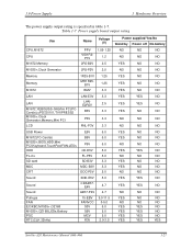
...P3V 3.3 NO NO NO LCD PNL-P3V 3.3 NO NO NO USB Power E5V 5.0 YES NO NO M1672,PC-Card(s) B5V 5.0 YES NO NO M1535+,BIOS,HDD,Mini PCI,Keyboard,TouchPad,FAN,LEDs P5V 5.0 NO NO NO ODD ... NO FL-inv FL-P5V 5.0 NO NO NO SD card SD-B3V 3.3 YES NO NO MDC CRT MDC-B3V 3.3 YES NO NO DDC-P5V 5.0 NO NO NO Sound Sound Sound Pull-ups FAN EC/KBC,M1535+,OZ168 M1535+,OZ168,LEDs,...YES YES NO NO NO NO NO NO NO NO YES Satellite A20 Maintenance Manual (960-444) 1-27 1.9 Power Supply 1 Hardware Overview The power supply output rating is specified in table 1-7.
...P3V 3.3 NO NO NO LCD PNL-P3V 3.3 NO NO NO USB Power E5V 5.0 YES NO NO M1672,PC-Card(s) B5V 5.0 YES NO NO M1535+,BIOS,HDD,Mini PCI,Keyboard,TouchPad,FAN,LEDs P5V 5.0 NO NO NO ODD ... NO FL-inv FL-P5V 5.0 NO NO NO SD card SD-B3V 3.3 YES NO NO MDC CRT MDC-B3V 3.3 YES NO NO DDC-P5V 5.0 NO NO NO Sound Sound Sound Pull-ups FAN EC/KBC,M1535+,OZ168 M1535+,OZ168,LEDs,...YES YES NO NO NO NO NO NO NO NO YES Satellite A20 Maintenance Manual (960-444) 1-27 1.9 Power Supply 1 Hardware Overview The power supply output rating is specified in table 1-7.

Maintenance Manual
Page 48
... Check 2-53 Procedure 3 Antenna Check 2-54 Procedure 4 Replacement Check 2-55 2.13 Sound Troubleshooting 2-56 Procedure 1 Diagnostic Test Program Execution Check 2-56 Procedure 2 Connector Check 2-57 Procedure 3 Replacement Check 2-58 2.14 SD Card Troubleshooting 2-59 Procedure 1 Check on Windows XP Pro/Home 2-59 Procedure 2 Connector/Replacement Check 2-59 2-iv Satellite A20 Maintenance Manual (960-444)
... Check 2-53 Procedure 3 Antenna Check 2-54 Procedure 4 Replacement Check 2-55 2.13 Sound Troubleshooting 2-56 Procedure 1 Diagnostic Test Program Execution Check 2-56 Procedure 2 Connector Check 2-57 Procedure 3 Replacement Check 2-58 2.14 SD Card Troubleshooting 2-59 Procedure 1 Check on Windows XP Pro/Home 2-59 Procedure 2 Connector/Replacement Check 2-59 2-iv Satellite A20 Maintenance Manual (960-444)

Maintenance Manual
Page 51
... TSD-1 (TOSHIBA EMI DVD Test Media) Satellite A20 Maintenance Manual (960-444) 2-1 Toshiba MS-DOS system disk(s) (You must install the following tools are described in and line-out ports 15. Printer port LED 8. Display 9. Cleaning kit for floppy disk drive troubleshooting 6. USB test module and USB cable 18. Wireless LAN 2. Sound components 3. SD card 4. Printer...
... TSD-1 (TOSHIBA EMI DVD Test Media) Satellite A20 Maintenance Manual (960-444) 2-1 Toshiba MS-DOS system disk(s) (You must install the following tools are described in and line-out ports 15. Printer port LED 8. Display 9. Cleaning kit for floppy disk drive troubleshooting 6. USB test module and USB cable 18. Wireless LAN 2. Sound components 3. SD card 4. Printer...

Maintenance Manual
Page 78
2 Troubleshooting Procedures 2.12 Sound Troubleshooting Table 2-3 Printer port LED boot mode status (6/8) LED Status 09h 0Ah 0Bh 0Ch ... a task for waiting the completion of PnP resource creating Serial interrupt control (before executing interrupt) PnP Hardware initialization PC card slot initialization FIR initialization PCI auto configuration Preparing work for auto configuration Acquiring PCI IRQ Configuration Storing the result of VGA... Logo Display Conventional memory check (Boot) Check of exceptional cases in protected mode (Boot) 2-28 Satellite A20 Maintenance Manual (960-444)
2 Troubleshooting Procedures 2.12 Sound Troubleshooting Table 2-3 Printer port LED boot mode status (6/8) LED Status 09h 0Ah 0Bh 0Ch ... a task for waiting the completion of PnP resource creating Serial interrupt control (before executing interrupt) PnP Hardware initialization PC card slot initialization FIR initialization PCI auto configuration Preparing work for auto configuration Acquiring PCI IRQ Configuration Storing the result of VGA... Logo Display Conventional memory check (Boot) Check of exceptional cases in protected mode (Boot) 2-28 Satellite A20 Maintenance Manual (960-444)

Maintenance Manual
Page 80
2 Troubleshooting Procedures 2.12 Sound Troubleshooting Table 2-3 Printer port LED boot mode status (8/8) LED Status (1Ch) Test item FFh End Message ...Clearing runtime flag in IRT Update of runtime checksum Hibernation branch Bluetooth initialization Check the presence of a target maintenance card Disabling the PC card not used Hardware initialization Pre Boot Notifying the conditional of DVI connection to VGA BIOS Setting of the battery ... button Enabling the power button Measure against the operation failure of USB at high temperature 2-30 Satellite A20 Maintenance Manual (960-444)
2 Troubleshooting Procedures 2.12 Sound Troubleshooting Table 2-3 Printer port LED boot mode status (8/8) LED Status (1Ch) Test item FFh End Message ...Clearing runtime flag in IRT Update of runtime checksum Hibernation branch Bluetooth initialization Check the presence of a target maintenance card Disabling the PC card not used Hardware initialization Pre Boot Notifying the conditional of DVI connection to VGA BIOS Setting of the battery ... button Enabling the power button Measure against the operation failure of USB at high temperature 2-30 Satellite A20 Maintenance Manual (960-444)

Maintenance Manual
Page 98
...If the modem is still not functioning properly, perform Check 3. Disassemble the computer following the steps described in Chapter 4, Replacement Procedures. 2-48 Satellite A20 Maintenance Manual (960-444) Check 3 The MDC may be defective or damaged. Replace the RJ-11 jack with a new one following the... or damaged. Check 2 The RJ-11 jack may be defective or damaged. Check 4 The sound board or system board may be damaged. If the Modem is installed as a modem daughter card (MDC). If a connector is firmly connected to MDC JP1. 2 Troubleshooting Procedures 2.10 Modem ...
...If the modem is still not functioning properly, perform Check 3. Disassemble the computer following the steps described in Chapter 4, Replacement Procedures. 2-48 Satellite A20 Maintenance Manual (960-444) Check 3 The MDC may be defective or damaged. Replace the RJ-11 jack with a new one following the... or damaged. Check 2 The RJ-11 jack may be defective or damaged. Check 4 The sound board or system board may be damaged. If the Modem is installed as a modem daughter card (MDC). If a connector is firmly connected to MDC JP1. 2 Troubleshooting Procedures 2.10 Modem ...

Maintenance Manual
Page 108
...properly. Procedure 2 Connector/Replacement Check The SD card is not recognized or data are not read . Check 1 The SD card and the sound board may be faulty. If not, insert it with a new one following the step in Chapter 4. 2-58 Satellite A20 Maintenance Manual (960-444) If the problem ...continues, perform Check 3. If the SD card is firmly connected to PJ2130 on ...
...properly. Procedure 2 Connector/Replacement Check The SD card is not recognized or data are not read . Check 1 The SD card and the sound board may be faulty. If not, insert it with a new one following the step in Chapter 4. 2-58 Satellite A20 Maintenance Manual (960-444) If the problem ...continues, perform Check 3. If the SD card is firmly connected to PJ2130 on ...

Maintenance Manual
Page 115
Satellite A20 Maintenance Manual ... DVD test media (Toshiba-EMI DVD-ROM TEST DISK TSD-1) (CD-ROM/DVD- Refer to clean the DVD-ROM drive heads (Head Cleaning) q A PC card wraparound connector for the I/O card test (Expansion test)... (Rev.B or higher) q A printer wraparound connector for detailed information on the remaining Service Program Module functions. ROM test) q CD-RW media that supports four-speed writing (media manufactured by RICOH or Mitsubishi Chemical are recommended.) q External CRT (Display test) q Headphone (Sound...
Satellite A20 Maintenance Manual ... DVD test media (Toshiba-EMI DVD-ROM TEST DISK TSD-1) (CD-ROM/DVD- Refer to clean the DVD-ROM drive heads (Head Cleaning) q A PC card wraparound connector for the I/O card test (Expansion test)... (Rev.B or higher) q A printer wraparound connector for detailed information on the remaining Service Program Module functions. ROM test) q CD-RW media that supports four-speed writing (media manufactured by RICOH or Mitsubishi Chemical are recommended.) q External CRT (Display test) q Headphone (Sound...
Maintenance Manual
Page 203
...26 4.10 Keyboard ...4-31 4.11 Memory Module...4-35 4.12 Wireless LAN Card 4-37 4.13 Bluetooth...4-40 4.14 Top Cover with Display Assembly 4-42 4.15 Touch Pad ...4-45 4.16 Front Membrane ASSY 4-47 4.17 FIR Board ...4-49 4.18 Sound Board ...4-51 4.19 RTC Battery...4-53 4.20 DC-IN Jack ...4-55 ...4.21 System Board ...4-56 4.22 Sub Fan...4-58 4.23 PC Card Slot...4-60 4.24 Speakers ...4-62 4.25 Touch Pad Switch...4-64 4.26 Display Mask...4-65 4.27 FL Inverter ...4-67 4.28 LCD Module ...4-69 Satellite A20 Maintenance Manual...
...26 4.10 Keyboard ...4-31 4.11 Memory Module...4-35 4.12 Wireless LAN Card 4-37 4.13 Bluetooth...4-40 4.14 Top Cover with Display Assembly 4-42 4.15 Touch Pad ...4-45 4.16 Front Membrane ASSY 4-47 4.17 FIR Board ...4-49 4.18 Sound Board ...4-51 4.19 RTC Battery...4-53 4.20 DC-IN Jack ...4-55 ...4.21 System Board ...4-56 4.22 Sub Fan...4-58 4.23 PC Card Slot...4-60 4.24 Speakers ...4-62 4.25 Touch Pad Switch...4-64 4.26 Display Mask...4-65 4.27 FL Inverter ...4-67 4.28 LCD Module ...4-69 Satellite A20 Maintenance Manual...
Maintenance Manual
Page 205
...ASSY 4-47 Removing the FIR board 4-49 Removing the Sound board 4-51 Removing the RTC battery 4-54 Removing the DC-IN jack 4-55 Removing the System board 4-56 Removing the Sub Fan 4-58 Removing the PC card slot 4-60 Removing the Speakers 4-62 Removing the Side ...Removing the Display mask (1 4-65 Removing the Display mask (2 4-66 Removing the FL inverter 4-67 Removing the LCD module (1 4-70 Removing the LCD module (2 4-71 Removing the Latch assembly 4-73 Removing the Wireless LAN/Bluetooth antenna 4-74 Removing the LCD cable (1 4-75 Satellite A20 Maintenance Manual (960-444) 4-v
...ASSY 4-47 Removing the FIR board 4-49 Removing the Sound board 4-51 Removing the RTC battery 4-54 Removing the DC-IN jack 4-55 Removing the System board 4-56 Removing the Sub Fan 4-58 Removing the PC card slot 4-60 Removing the Speakers 4-62 Removing the Side ...Removing the Display mask (1 4-65 Removing the Display mask (2 4-66 Removing the FL inverter 4-67 Removing the LCD module (1 4-70 Removing the LCD module (2 4-71 Removing the Latch assembly 4-73 Removing the Wireless LAN/Bluetooth antenna 4-74 Removing the LCD cable (1 4-75 Satellite A20 Maintenance Manual (960-444) 4-v

Maintenance Manual
Page 230
... refer to disconnect it from JP1 on the sound board. 4. Carefully lift up the modem daughter card to figure 4-7. 1. Turn over the insulator covering the modem daughter card. 3. Carefully disconnect the modem cable from PJ3010 on the modem daughter card. Figure 4-7 Removing the Modem daughter card 4-20 Satellite A20 Maintenance Manual (960-444) Remove the following screws...
... refer to disconnect it from JP1 on the sound board. 4. Carefully lift up the modem daughter card to figure 4-7. 1. Turn over the insulator covering the modem daughter card. 3. Carefully disconnect the modem cable from PJ3010 on the modem daughter card. Figure 4-7 Removing the Modem daughter card 4-20 Satellite A20 Maintenance Manual (960-444) Remove the following screws...

Maintenance Manual
Page 231
... the modem daughter card with the following screws. • M2×3 SUPER FLAT screw ×2 Satellite A20 Maintenance Manual (960-444) 4-21 Carefully connect the modem cable to PJ3010 on the sound board. Seat the modem daughter card and press carefully on the right end of the card to connect it... to JP1 on the modem daughter card slot. 3. Turn over the...
... the modem daughter card with the following screws. • M2×3 SUPER FLAT screw ×2 Satellite A20 Maintenance Manual (960-444) 4-21 Carefully connect the modem cable to PJ3010 on the sound board. Seat the modem daughter card and press carefully on the right end of the card to connect it... to JP1 on the modem daughter card slot. 3. Turn over the...

Maintenance Manual
Page 267
... direction in the figure. 4. Disconnect the sound board SUMI card from PJ9510 and PJ9511 on the sound board. Figure 4-28 Removing the Sound board 4-54 Satellite A20 Maintenance Manual (960-444) Remove the following screw securing the sound board. • M2.5×6 FLAT HEAD screw ×1 3. Disconnect the sound board SUMI card from PJ9600 and PJ9601 on the system...
... direction in the figure. 4. Disconnect the sound board SUMI card from PJ9510 and PJ9511 on the sound board. Figure 4-28 Removing the Sound board 4-54 Satellite A20 Maintenance Manual (960-444) Remove the following screw securing the sound board. • M2.5×6 FLAT HEAD screw ×1 3. Disconnect the sound board SUMI card from PJ9600 and PJ9601 on the system...


