Toshiba Online Users Guide for Satellite A100/A105
Page 2
... THE PRODUCT WILL BE UNINTERRUPTED OR ERROR FREE. TOSHIBA DISCLAIMS ANY LIABILITY FOR THE FAILURE TO COPY OR TRANSFER THE DATA CORRECTLY. WHEN COPYING OR TRANSFERRING YOUR DATA, PLEASE BE SURE TO CONFIRM WHETHER THE DATA HAS BEEN SUCCESSFULLY COPIED OR TRANSFERRED. Model: Satellite® A100/A105 Recordable and/or ReWritable Drive(s) and Associated...
... THE PRODUCT WILL BE UNINTERRUPTED OR ERROR FREE. TOSHIBA DISCLAIMS ANY LIABILITY FOR THE FAILURE TO COPY OR TRANSFER THE DATA CORRECTLY. WHEN COPYING OR TRANSFERRING YOUR DATA, PLEASE BE SURE TO CONFIRM WHETHER THE DATA HAS BEEN SUCCESSFULLY COPIED OR TRANSFERRED. Model: Satellite® A100/A105 Recordable and/or ReWritable Drive(s) and Associated...
Maintenance Manual
Page 4
...NOTE: "Note" contains general information that could result in property damage, if the safety instruction is not observed. iv Satellite A100/A105 / TECRA A7 Maintenance Manual Each of the wrong battery can cause the battery to your attention. If you replace the... same model battery or an equivalent battery recommended by Toshiba. DANGER: "Danger" indicates the existence of a hazard that could cause overheating, smoke or fire. ? Preface This maintenance manual describes how to perform hardware service maintenance for the Toshiba Personal Computer Satellite A100/A105 / TECRA...
...NOTE: "Note" contains general information that could result in property damage, if the safety instruction is not observed. iv Satellite A100/A105 / TECRA A7 Maintenance Manual Each of the wrong battery can cause the battery to your attention. If you replace the... same model battery or an equivalent battery recommended by Toshiba. DANGER: "Danger" indicates the existence of a hazard that could cause overheating, smoke or fire. ? Preface This maintenance manual describes how to perform hardware service maintenance for the Toshiba Personal Computer Satellite A100/A105 / TECRA...

Maintenance Manual
Page 12
... Installing the Top Cover 4-38 4.9 CPU Cooling Module and Fan 4-39 Removing the CPU Cooling and Fan (for VGA Card Model 4-39 Installing the CPU Cooling and Fan (for VGA Card Model 4-41 Removing the CPU Cooling and Fan 4-42 Installing the CPU Cooling and Fan 4-43 4.10 VGA Card (for VGA... Card Model Only 4-44 Removing the VGA Card 4-44 Installing the VGA Card 4-45 4.11 CPU ...4-46 Removing the CPU 4-46 Installing the CPU 4-47 4.12 USB ...
... Installing the Top Cover 4-38 4.9 CPU Cooling Module and Fan 4-39 Removing the CPU Cooling and Fan (for VGA Card Model 4-39 Installing the CPU Cooling and Fan (for VGA Card Model 4-41 Removing the CPU Cooling and Fan 4-42 Installing the CPU Cooling and Fan 4-43 4.10 VGA Card (for VGA... Card Model Only 4-44 Removing the VGA Card 4-44 Installing the VGA Card 4-45 4.11 CPU ...4-46 Removing the CPU 4-46 Installing the CPU 4-47 4.12 USB ...
Maintenance Manual
Page 13
... Cover and Switch Board 4-61 Removing the Switch Cover and Switch Board (For Consumer Model 4-61 Installing the Switch Cover and Switch Board 4-62 Removing the Switch Cover and Switch Board (For Commercial Model 4-63 Installing the Switch Cover and Switch Board 4-64 4.19 Touch Pad and Touch...65 Removing the Touch Pad and Touch Pad Board (For Consumer Model 4-65 Installing the Touch Pad and Touch Pad Board 4-66 Removing the Touch Pad and Touch Pad Board (For Commercial Model 4-67 Installing the Touch Pad and Touch Pad Board 4-68 Satellite A100/A105 / TECRA A7 Maintenance Manual xiii
... Cover and Switch Board 4-61 Removing the Switch Cover and Switch Board (For Consumer Model 4-61 Installing the Switch Cover and Switch Board 4-62 Removing the Switch Cover and Switch Board (For Commercial Model 4-63 Installing the Switch Cover and Switch Board 4-64 4.19 Touch Pad and Touch...65 Removing the Touch Pad and Touch Pad Board (For Consumer Model 4-65 Installing the Touch Pad and Touch Pad Board 4-66 Removing the Touch Pad and Touch Pad Board (For Commercial Model 4-67 Installing the Touch Pad and Touch Pad Board 4-68 Satellite A100/A105 / TECRA A7 Maintenance Manual xiii

Maintenance Manual
Page 149
... Installing the Top Cover 4-38 4.9 CPU Cooling Module and Fan 4-39 Removing the CPU Cooling and Fan (for VGA Card Model 4-39 Installing the CPU Cooling and Fan (for VGA Card Model 4-41 Removing the CPU Cooling and Fan 4-42 Installing the CPU Cooling and Fan 4-43 4.10 VGA Card (for VGA... Card Model Only 4-44 Removing the VGA Card 4-44 Installing the VGA Card 4-45 4.11 CPU...4-46 Removing the CPU 4-46 Installing the CPU 4-47 4.12 USB Board, Finger Print Board and Print Board 4-49 4-iv Satellite A100/A105 / TECRA A7 Maintenance Manual
... Installing the Top Cover 4-38 4.9 CPU Cooling Module and Fan 4-39 Removing the CPU Cooling and Fan (for VGA Card Model 4-39 Installing the CPU Cooling and Fan (for VGA Card Model 4-41 Removing the CPU Cooling and Fan 4-42 Installing the CPU Cooling and Fan 4-43 4.10 VGA Card (for VGA... Card Model Only 4-44 Removing the VGA Card 4-44 Installing the VGA Card 4-45 4.11 CPU...4-46 Removing the CPU 4-46 Installing the CPU 4-47 4.12 USB Board, Finger Print Board and Print Board 4-49 4-iv Satellite A100/A105 / TECRA A7 Maintenance Manual

Maintenance Manual
Page 150
... Cover and Switch Board 4-61 Removing the Switch Cover and Switch Board (For Consumer Model 4-61 Installing the Switch Cover and Switch Board 4-62 Removing the Switch Cover and Switch Board (For Commercial Model 4-63 Installing the Switch Cover and Switch Board 4-64 4.19 Touch Pad and Touch... 4-65 Removing the Touch Pad and Touch Pad Board (For Consumer Model 4-65 Installing the Touch Pad and Touch Pad Board 4-66 Removing the Touch Pad and Touch Pad Board (For Commercial Model 4-67 Installing the Touch Pad and Touch Pad Board 4-68 Satellite A100/A105 / TECRA A7 Maintenance Manual 4-v
... Cover and Switch Board 4-61 Removing the Switch Cover and Switch Board (For Consumer Model 4-61 Installing the Switch Cover and Switch Board 4-62 Removing the Switch Cover and Switch Board (For Commercial Model 4-63 Installing the Switch Cover and Switch Board 4-64 4.19 Touch Pad and Touch... 4-65 Removing the Touch Pad and Touch Pad Board (For Consumer Model 4-65 Installing the Touch Pad and Touch Pad Board 4-66 Removing the Touch Pad and Touch Pad Board (For Commercial Model 4-67 Installing the Touch Pad and Touch Pad Board 4-68 Satellite A100/A105 / TECRA A7 Maintenance Manual 4-v

Maintenance Manual
Page 192
...using the indicated order. 6. Do not touch or cause damage to the fan in mind: The cooling module can become very hot during operation. Satellite A100/A105 / TECRA A7 Maintenance Manual 4-39 Be sure to the following in the cooling module. Remove the CPU bracket. 5. NOTE: The screws for... VGA card Model) Remove the CPU cooling module and fan according to let it cool down before starting the repair work. Remove two M2x4 white...
...using the indicated order. 6. Do not touch or cause damage to the fan in mind: The cooling module can become very hot during operation. Satellite A100/A105 / TECRA A7 Maintenance Manual 4-39 Be sure to the following in the cooling module. Remove the CPU bracket. 5. NOTE: The screws for... VGA card Model) Remove the CPU cooling module and fan according to let it cool down before starting the repair work. Remove two M2x4 white...

Maintenance Manual
Page 194
... the surface of the CPU chip completely. 1. NOTE: Apply silicon grease with a special syringe to confirm the correct position for VGA card Model) Install the cooling Module according to the following in mind: 1. Connect the fan cable to CN13 on heat sink module. Secure the VGA ... them off with the grease. 2. Secures the relevant screws on the main board according to the number sequence sealed on the system board 4. Satellite A100/A105 / TECRA A7 Maintenance Manual 4-41 CAUTION: When installing the cooling module, keep the following procedures and Figures 4-23, 4-24. By using ...
... the surface of the CPU chip completely. 1. NOTE: Apply silicon grease with a special syringe to confirm the correct position for VGA card Model) Install the cooling Module according to the following in mind: 1. Connect the fan cable to CN13 on heat sink module. Secure the VGA ... them off with the grease. 2. Secures the relevant screws on the main board according to the number sequence sealed on the system board 4. Satellite A100/A105 / TECRA A7 Maintenance Manual 4-41 CAUTION: When installing the cooling module, keep the following procedures and Figures 4-23, 4-24. By using ...

Maintenance Manual
Page 197
Figure 4-27 Removing the VGA board 4-44 Satellite A100/A105 / TECRA A7 Maintenance Manual Remove two M2x4 white flat-head screws. 2. Remove the VGA board. 4 Replacement Procedures 4.10 VGA Board (for VGA Board Model) 4.10 VGA Board (for VGA Board Model) Removing the VGA Board Remove the VGA board according to the following procedures and Figures 4-27. 1.
Figure 4-27 Removing the VGA board 4-44 Satellite A100/A105 / TECRA A7 Maintenance Manual Remove two M2x4 white flat-head screws. 2. Remove the VGA board. 4 Replacement Procedures 4.10 VGA Board (for VGA Board Model) 4.10 VGA Board (for VGA Board Model) Removing the VGA Board Remove the VGA board according to the following procedures and Figures 4-27. 1.
Maintenance Manual
Page 198
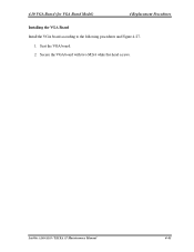
Secure the VGA board with two M2x4 white flat-head screws. Satellite A100/A105 / TECRA A7 Maintenance Manual 4-45 Seat the VGA board. 2. 4.10 VGA Board (for VGA Board Model) 4 Replacement Procedures Installing the VGA Board Install the VGA board according to the following procedures and Figure 4-27. 1.
Secure the VGA board with two M2x4 white flat-head screws. Satellite A100/A105 / TECRA A7 Maintenance Manual 4-45 Seat the VGA board. 2. 4.10 VGA Board (for VGA Board Model) 4 Replacement Procedures Installing the VGA Board Install the VGA board according to the following procedures and Figure 4-27. 1.

Maintenance Manual
Page 214
Remove two M2.5x4 black flat-head screws. Figure 4-38 Removing the switch cover 4. Remove the following procedures and Figures 438, 4-39. 1. Satellite A100/A105 / TECRA A7 Maintenance Manual 4-61 Remove the Mylar and EMI tape. 2. One latch on the switch cover, in that order: - Turn the top cover...latches - 4.18 Switch Cover and Switch board 4 Replacement Procedures 4.18 Switch Cover and Switch Board Removing the Switch Cover and Switch Board (for Consumer Model) Remove the Switch Cover and Switch Board according to the following 7 latches on the front and bottom sides -
Remove two M2.5x4 black flat-head screws. Figure 4-38 Removing the switch cover 4. Remove the following procedures and Figures 438, 4-39. 1. Satellite A100/A105 / TECRA A7 Maintenance Manual 4-61 Remove the Mylar and EMI tape. 2. One latch on the switch cover, in that order: - Turn the top cover...latches - 4.18 Switch Cover and Switch board 4 Replacement Procedures 4.18 Switch Cover and Switch Board Removing the Switch Cover and Switch Board (for Consumer Model) Remove the Switch Cover and Switch Board according to the following 7 latches on the front and bottom sides -

Maintenance Manual
Page 216
Remove two M2.5x4 black flat-head screws. Figure 4-40 Removing the switch board 4. Remove the Mylar and EMI tape. 2. Remove the switch board. 4.18 Switch Cover and Switch board 4 Replacement Procedures Removing the Switch Cover and Switch Board (for Commercial Model) Remove the Switch Cover and Switch Board according to the following procedures and Figure 440. 1. Satellite A100/A105 / TECRA A7 Maintenance Manual 4-63 Disconnect the switch board flat cables from CN4000 on the switch board. 3.
Remove two M2.5x4 black flat-head screws. Figure 4-40 Removing the switch board 4. Remove the Mylar and EMI tape. 2. Remove the switch board. 4.18 Switch Cover and Switch board 4 Replacement Procedures Removing the Switch Cover and Switch Board (for Commercial Model) Remove the Switch Cover and Switch Board according to the following procedures and Figure 440. 1. Satellite A100/A105 / TECRA A7 Maintenance Manual 4-63 Disconnect the switch board flat cables from CN4000 on the switch board. 3.

Maintenance Manual
Page 218
Remove five M2.5x4 black flat-head screws securing the touch pad. 3. Satellite A100/A105 / TECRA A7 Maintenance Manual 4-65 Disconnect the touch pad flat cables from CN2000 on the touch pad. 2. Figure 4-41 Removing the touch pad and button ... button board. 6. 4.19 Touch Pad and Button Board 4 Replacement Procedures 4.19 Touch Pad and Button Board Removing the Touch Pad and Button Board (for Consumer Model) Remove the touch pad and button board according to the following procedures and Figure 4-41. 1.
Remove five M2.5x4 black flat-head screws securing the touch pad. 3. Satellite A100/A105 / TECRA A7 Maintenance Manual 4-65 Disconnect the touch pad flat cables from CN2000 on the touch pad. 2. Figure 4-41 Removing the touch pad and button ... button board. 6. 4.19 Touch Pad and Button Board 4 Replacement Procedures 4.19 Touch Pad and Button Board Removing the Touch Pad and Button Board (for Consumer Model) Remove the touch pad and button board according to the following procedures and Figure 4-41. 1.

Maintenance Manual
Page 220
... black flat-head screws securing the touch pad. 4. 4.19 Touch Pad and Button Board 4 Replacement Procedures Removing the Touch Pad and Button Board (for Commercial Model) Remove the touch pad and button board according to the following procedures and Figure 4-42. 1. Disconnect the touch pad flat cables from CN2000 on the...
... black flat-head screws securing the touch pad. 4. 4.19 Touch Pad and Button Board 4 Replacement Procedures Removing the Touch Pad and Button Board (for Commercial Model) Remove the touch pad and button board according to the following procedures and Figure 4-42. 1. Disconnect the touch pad flat cables from CN2000 on the...
Maintenance Manual
Page 272
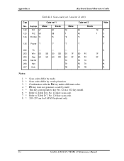
... key corresponds to Table D-6, No. 124 key scan code. Fn key does not generate a code by mode. Refer to key No. 42 in a 102-key model. Scan codes differ by overlay function. Refer to Table D-7, No. 126 key scan code. 205~207 are for JAPAN keyboard only *4 1F 2F...
... key corresponds to Table D-6, No. 124 key scan code. Fn key does not generate a code by mode. Refer to key No. 42 in a 102-key model. Scan codes differ by overlay function. Refer to Table D-7, No. 126 key scan code. 205~207 are for JAPAN keyboard only *4 1F 2F...

Maintenance Manual
Page 294
Apx. H GREASE INFORMATION Appendix H Appendix H GREASE INFORMATION This Appendix explains which grease use this model. Appendices Satellite A100/A105 / TECRA A7 Maintenance Manual H-1
Apx. H GREASE INFORMATION Appendix H Appendix H GREASE INFORMATION This Appendix explains which grease use this model. Appendices Satellite A100/A105 / TECRA A7 Maintenance Manual H-1


