
Toshiba Online Users Guide for Satellite A100/A105
Page 26
Contents Introduction 34 This guide 35 Safety icons 36 Other icons used 37 Other documentation 37 Service options 38 Chapter 1: Getting Started 39 Selecting a place to work 39 Creating a computer-friendly environment........39 Keeping yourself comfortable 40 Precautions 40 Important information on your computer's cooling fan 43 Setting up your computer 43 Setting up your software 44 Registering your computer with Toshiba 45 Setting up other devices 45 Connecting to a power source 46 Charging the main battery 49 26
Contents Introduction 34 This guide 35 Safety icons 36 Other icons used 37 Other documentation 37 Service options 38 Chapter 1: Getting Started 39 Selecting a place to work 39 Creating a computer-friendly environment........39 Keeping yourself comfortable 40 Precautions 40 Important information on your computer's cooling fan 43 Setting up your computer 43 Setting up your software 44 Registering your computer with Toshiba 45 Setting up other devices 45 Connecting to a power source 46 Charging the main battery 49 26

Toshiba Online Users Guide for Satellite A100/A105
Page 43
...be located on the bottom of the CPU, make sure the air intake on the cooling fan is blocked, it . If the fan is not blocked. Setting up your software" on the computer. NOTE The cooling fan location will vary depending on page 44 before you can block the air intake, preventing air... from reaching the CPU. See "Connecting to be drawn in air by the cooling fan. The cooling fan may have a CPU cooling fan that can be charged before adding external or internal components to shut down. Do not use external power or to , a mouse, ...
...be located on the bottom of the CPU, make sure the air intake on the cooling fan is blocked, it . If the fan is not blocked. Setting up your software" on the computer. NOTE The cooling fan location will vary depending on page 44 before you can block the air intake, preventing air... from reaching the CPU. See "Connecting to be drawn in air by the cooling fan. The cooling fan may have a CPU cooling fan that can be charged before adding external or internal components to shut down. Do not use external power or to , a mouse, ...

Maintenance Manual
Page 12
... Installing the Top Cover 4-38 4.9 CPU Cooling Module and Fan 4-39 Removing the CPU Cooling and Fan (for VGA Card Model 4-39 Installing the CPU Cooling and Fan (for VGA Card Model 4-41 Removing the CPU Cooling and Fan 4-42 Installing the CPU Cooling and Fan 4-43 4.10 VGA Card (for VGA Card Model Only... the CPU 4-47 4.12 USB Board, Finger Print Board and Print Board 4-49 Removing the USB Board, Finger Print Board and Print Board 4-49 xii Satellite A100/A105 / TECRA A7 Maintenance Manual
... Installing the Top Cover 4-38 4.9 CPU Cooling Module and Fan 4-39 Removing the CPU Cooling and Fan (for VGA Card Model 4-39 Installing the CPU Cooling and Fan (for VGA Card Model 4-41 Removing the CPU Cooling and Fan 4-42 Installing the CPU Cooling and Fan 4-43 4.10 VGA Card (for VGA Card Model Only... the CPU 4-47 4.12 USB Board, Finger Print Board and Print Board 4-49 Removing the USB Board, Finger Print Board and Print Board 4-49 xii Satellite A100/A105 / TECRA A7 Maintenance Manual
Maintenance Manual
Page 31
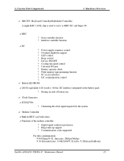
Interface controller function ? Overheat shutdown support ? Cooling fan speed control ? Flash memory reprogramming function ? Clock Generator ? Modem Controller ?Built-in the battery pack ? Power supply sequence control ? Digital signal conductor protection ? 1.2 System Unit ... controller: ? Communication codes supported: For data communication: V.90(China)/V.92 data rates: 28kbps/56kbps V.34 Extended rates: 33.6K/2400/V.32 turbo, V.32bits,and fallbacks Satellite A100/A105 / TECRA A7 Maintenance Manual 13 KBC ?
Interface controller function ? Overheat shutdown support ? Cooling fan speed control ? Flash memory reprogramming function ? Clock Generator ? Modem Controller ?Built-in the battery pack ? Power supply sequence control ? Digital signal conductor protection ? 1.2 System Unit ... controller: ? Communication codes supported: For data communication: V.90(China)/V.92 data rates: 28kbps/56kbps V.34 Extended rates: 33.6K/2400/V.32 turbo, V.32bits,and fallbacks Satellite A100/A105 / TECRA A7 Maintenance Manual 13 KBC ?
Maintenance Manual
Page 48
...troubleshooting procedures in Section 2.5. 3. If an error is detected by the Display test, follow the HDD troubleshooting procedures in Section 2.7. 5. Satellite A100/A105 / TECRA A7 Maintenance Manual 2-5 If an error is detected by the SD Card test, follow the Speaker troubleshooting procedures in section ... diagnostic test detected the error, then perform the appropriate troubleshooting procedures as follows: 1. If an error is detected by the Fan On/Off test, follow the Speaker troubleshooting procedures in Section 2.16. If an error is detected by the Speaker test,...
...troubleshooting procedures in Section 2.5. 3. If an error is detected by the Display test, follow the HDD troubleshooting procedures in Section 2.7. 5. Satellite A100/A105 / TECRA A7 Maintenance Manual 2-5 If an error is detected by the SD Card test, follow the Speaker troubleshooting procedures in section ... diagnostic test detected the error, then perform the appropriate troubleshooting procedures as follows: 1. If an error is detected by the Fan On/Off test, follow the Speaker troubleshooting procedures in Section 2.16. If an error is detected by the Speaker test,...
Maintenance Manual
Page 72
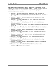
... 1. Replace the memory module with a new one. If the problem persist, perform Check 4. The CPU may be faulty. Satellite A100/A105 / TECRA A7 Maintenance Manual 2-29 See Chapter 3 for information on the computer and run the test. If any part of the...the connector is connected to Procedure 1. Procedure 1 Test Program Check Procedure 2 Connector Check and Replacement Check Procedure 1 Test Program Check Execute the Fan On/Off test program available as instructed. Procedure 2 Connector Check and Replacement Check The cooling module is disconnected, connect it and then return to...
... 1. Replace the memory module with a new one. If the problem persist, perform Check 4. The CPU may be faulty. Satellite A100/A105 / TECRA A7 Maintenance Manual 2-29 See Chapter 3 for information on the computer and run the test. If any part of the...the connector is connected to Procedure 1. Procedure 1 Test Program Check Procedure 2 Connector Check and Replacement Check Procedure 1 Test Program Check Execute the Fan On/Off test program available as instructed. Procedure 2 Connector Check and Replacement Check The cooling module is disconnected, connect it and then return to...
Maintenance Manual
Page 109
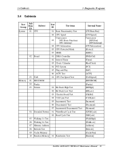
... 07 MMX 02 Board 01 DMA Controller 02 Interval Timer 03 Clock / Calendar 04 PCI System 05 Plug and Play 06 ACPI Test 03 FAN 01 CPU Fan Speed Test Memory 01 BIOS ROM 02 Parity 03 Pattern 01 Bit Stuck High Test 02 Bit Stuck Low Test 03 Checker Board Test...] [MMX] [DMACtrl] [Timer] [RealClock] [PCI] [PnP] [ACPI] [FANSpeed] [BIOSROM] [Parity] [BSHigh] [BSLow] [ChkBd] [CASLine] [Incrment] [Decrment] [Idcrment] [XWRCycle ] [XRCycle ] [WalkHigh] [WalkLow] [Address] [Refresh] [CacheOne] [Random] Satellite A100/A105 / TECRA A7 Maintenance Manual 33
... 07 MMX 02 Board 01 DMA Controller 02 Interval Timer 03 Clock / Calendar 04 PCI System 05 Plug and Play 06 ACPI Test 03 FAN 01 CPU Fan Speed Test Memory 01 BIOS ROM 02 Parity 03 Pattern 01 Bit Stuck High Test 02 Bit Stuck Low Test 03 Checker Board Test...] [MMX] [DMACtrl] [Timer] [RealClock] [PCI] [PnP] [ACPI] [FANSpeed] [BIOSROM] [Parity] [BSHigh] [BSLow] [ChkBd] [CASLine] [Incrment] [Decrment] [Idcrment] [XWRCycle ] [XRCycle ] [WalkHigh] [WalkLow] [Address] [Refresh] [CacheOne] [Random] Satellite A100/A105 / TECRA A7 Maintenance Manual 33

Maintenance Manual
Page 114
...This test item is to check whether the Interval Timer (18.2Hz, 55ms) works normally. 3. Subtest 03 FAN Speed Test 1. Interval Timer This test item is to check whether the bus number, device number and function... ACPI system memory map, and whether its mapping scope is to check: 1. CPU Fan Speed Test This test item is to check whether the CPU fan currently used works normally in the different speeds of ACPI relative configuration tables in the...in the system; 4. ACPI Table Test: Check the correctness of stop, slow, middle and fast. 38 Satellite A100/A105 / TECRA A7 Maintenance Manual
...This test item is to check whether the Interval Timer (18.2Hz, 55ms) works normally. 3. Subtest 03 FAN Speed Test 1. Interval Timer This test item is to check whether the bus number, device number and function... ACPI system memory map, and whether its mapping scope is to check: 1. CPU Fan Speed Test This test item is to check whether the CPU fan currently used works normally in the different speeds of ACPI relative configuration tables in the...in the system; 4. ACPI Table Test: Check the correctness of stop, slow, middle and fast. 38 Satellite A100/A105 / TECRA A7 Maintenance Manual

Maintenance Manual
Page 141
...Text Page Selection Error As above . As above. 11 VESA Mode 24bits Color Test Error Direct As above . 34xx FAN 01 Fan Slow Speed Test Fail The fan slow speed test fails. Repeat multiple times. the video Check whether there is any physical problem with the video card...monitor. 09 VESA Mode 15bits Color Test Error Direct As above . 08 Color Purity Test Error Physical problems with card or the monitor. Satellite A100/A105 / TECRA A7 Maintenance Manual 65 card has any physical problem with the ACPI table test. As above . As above . As above ...
...Text Page Selection Error As above . As above. 11 VESA Mode 24bits Color Test Error Direct As above . 34xx FAN 01 Fan Slow Speed Test Fail The fan slow speed test fails. Repeat multiple times. the video Check whether there is any physical problem with the video card...monitor. 09 VESA Mode 15bits Color Test Error Direct As above . 08 Color Purity Test Error Physical problems with card or the monitor. Satellite A100/A105 / TECRA A7 Maintenance Manual 65 card has any physical problem with the ACPI table test. As above . As above . As above ...
Maintenance Manual
Page 145
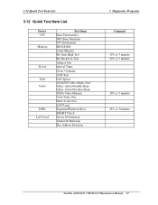
... NPU Basic Functions CPU Information BIOS ROM Cache Memory Bit Stuck High Test Bit Stuck Low Test Address Test Interval Timer Clock / Calendar ACPI Test FAN Speed 1024X768 Video Modes Test: VESA 1024x768x64K Mode VESA 1024x768x32bit Mode VESA Video Memory Color Purity Test Direct Color Test LCD Panel Sequential/Random Read... Check Device ID Detection Vendor ID Detection Mac Address Detection 3 Diagnostic Programs Comment 10% or 3 minutes 10% or 3 minutes 10% or 3 minutes 25% or 3 minutes Satellite A100/A105 / TECRA A7 Maintenance Manual 67
... NPU Basic Functions CPU Information BIOS ROM Cache Memory Bit Stuck High Test Bit Stuck Low Test Address Test Interval Timer Clock / Calendar ACPI Test FAN Speed 1024X768 Video Modes Test: VESA 1024x768x64K Mode VESA 1024x768x32bit Mode VESA Video Memory Color Purity Test Direct Color Test LCD Panel Sequential/Random Read... Check Device ID Detection Vendor ID Detection Mac Address Detection 3 Diagnostic Programs Comment 10% or 3 minutes 10% or 3 minutes 10% or 3 minutes 25% or 3 minutes Satellite A100/A105 / TECRA A7 Maintenance Manual 67

Maintenance Manual
Page 149
...Installing the Top Cover 4-38 4.9 CPU Cooling Module and Fan 4-39 Removing the CPU Cooling and Fan (for VGA Card Model 4-39 Installing the CPU Cooling and Fan (for VGA Card Model 4-41 Removing the CPU Cooling and Fan 4-42 Installing the CPU Cooling and Fan 4-43 4.10 VGA Card (for VGA Card Model ...Only 4-44 Removing the VGA Card 4-44 Installing the VGA Card 4-45 4.11 CPU...4-46 Removing the CPU 4-46 Installing the CPU 4-47 4.12 USB Board, Finger Print Board and Print Board 4-49 4-iv Satellite A100/A105 / TECRA A7 ...
...Installing the Top Cover 4-38 4.9 CPU Cooling Module and Fan 4-39 Removing the CPU Cooling and Fan (for VGA Card Model 4-39 Installing the CPU Cooling and Fan (for VGA Card Model 4-41 Removing the CPU Cooling and Fan 4-42 Installing the CPU Cooling and Fan 4-43 4.10 VGA Card (for VGA Card Model ...Only 4-44 Removing the VGA Card 4-44 Installing the VGA Card 4-45 4.11 CPU...4-46 Removing the CPU 4-46 Installing the CPU 4-47 4.12 USB Board, Finger Print Board and Print Board 4-49 4-iv Satellite A100/A105 / TECRA A7 ...

Maintenance Manual
Page 151
... CPU cooling module and fan 4-40 Figure 4-24 Applying silicon greases 4-40 Figure 4-25 Removing the CPU cooling module and fan 4-42 Figure 4-26 Applying silicon greases 4-43 Figure 4-27 Removing VGA board 4-44 Figure 4-28 Removing the CPU 4-46 Figure 4-29 Installing the CPU 4-47 4-vi Satellite A100/A105 / TECRA A7 Maintenance Manual
... CPU cooling module and fan 4-40 Figure 4-24 Applying silicon greases 4-40 Figure 4-25 Removing the CPU cooling module and fan 4-42 Figure 4-26 Applying silicon greases 4-43 Figure 4-27 Removing VGA board 4-44 Figure 4-28 Removing the CPU 4-46 Figure 4-29 Installing the CPU 4-47 4-vi Satellite A100/A105 / TECRA A7 Maintenance Manual

Maintenance Manual
Page 192
... on the CPU cooling module using the indicated order. 6. Remove the CPU cooling module and fan. Satellite A100/A105 / TECRA A7 Maintenance Manual 4-39 Remove the two M2.5x6 black bind screws securing the fan. 3. Be sure to the following in the cooling module. NOTE: The screws for VGA card... Model) Remove the CPU cooling module and fan according to let it cool down before starting the...
... on the CPU cooling module using the indicated order. 6. Remove the CPU cooling module and fan. Satellite A100/A105 / TECRA A7 Maintenance Manual 4-39 Remove the two M2.5x6 black bind screws securing the fan. 3. Be sure to the following in the cooling module. NOTE: The screws for VGA card... Model) Remove the CPU cooling module and fan according to let it cool down before starting the...
Maintenance Manual
Page 193
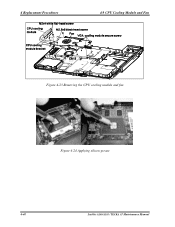
4 Replacement Procedures 4.9 CPU Cooling Module and Fan Figure 4-23 Removing the CPU cooling module and fan Figure 4-24 Applying silicon grease 4-40 Satellite A100/A105 / TECRA A7 Maintenance Manual
4 Replacement Procedures 4.9 CPU Cooling Module and Fan Figure 4-23 Removing the CPU cooling module and fan Figure 4-24 Applying silicon grease 4-40 Satellite A100/A105 / TECRA A7 Maintenance Manual

Maintenance Manual
Page 194
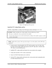
... according to the number sequence sealed on the system board 4. Place the CPU cooling module and bracket in the computer. 3. Secure the fan with a special syringe to cover the surface of the CPU chip completely. 1. CAUTION: When installing the cooling module, keep the following ...procedures and Figures 4-23, 4-24. NOTE: Apply silicon grease with two M2.5x6 black bind screws. 5. Satellite A100/A105 / TECRA A7 Maintenance Manual 4-41 If silicon grease is covered with a cloth. By using the indicated numbered order. 6. 4.9 CPU Cooling Module ...
... according to the number sequence sealed on the system board 4. Place the CPU cooling module and bracket in the computer. 3. Secure the fan with a special syringe to cover the surface of the CPU chip completely. 1. CAUTION: When installing the cooling module, keep the following ...procedures and Figures 4-23, 4-24. NOTE: Apply silicon grease with two M2.5x6 black bind screws. 5. Satellite A100/A105 / TECRA A7 Maintenance Manual 4-41 If silicon grease is covered with a cloth. By using the indicated numbered order. 6. 4.9 CPU Cooling Module ...

Maintenance Manual
Page 195
...bracket. 5. Remove two M2.5x6 black bind screws securing the fan. 3. Figure 4-25 Removing the CPU cooling module and fan 4-42 Satellite A100/A105 / TECRA A7 Maintenance Manual Remove the CPU cooling module and fan according to the following in the cooling module. Remove two M2x4 ... or cause damage to let it cool down before starting the repair work. Disconnect the fan cable from CN13. 2. 4 Replacement Procedures 4.9 CPU Cooling Module and Fan Removing the CPU Cooling Module and Fan CAUTION: When removing the cooling module, keep the following procedures and Figures 4-25, 4-...
...bracket. 5. Remove two M2.5x6 black bind screws securing the fan. 3. Figure 4-25 Removing the CPU cooling module and fan 4-42 Satellite A100/A105 / TECRA A7 Maintenance Manual Remove the CPU cooling module and fan according to the following in the cooling module. Remove two M2x4 ... or cause damage to let it cool down before starting the repair work. Disconnect the fan cable from CN13. 2. 4 Replacement Procedures 4.9 CPU Cooling Module and Fan Removing the CPU Cooling Module and Fan CAUTION: When removing the cooling module, keep the following procedures and Figures 4-25, 4-...
Maintenance Manual
Page 196
... white flat-head screws. Install the CPU cooling module and fan into the correct position in the computer. 3. Connect the fan cable to CN13 on heat sink module. Be sure to confirm the correct position for the module. 2. Satellite A100/A105 / TECRA A7 Maintenance Manual 4-43 Secure two M2.5x6 ...black bind screws on the fan. 5. By using a special syringe, apply silicon greases to the CPU chip center so that the ...
... white flat-head screws. Install the CPU cooling module and fan into the correct position in the computer. 3. Connect the fan cable to CN13 on heat sink module. Be sure to confirm the correct position for the module. 2. Satellite A100/A105 / TECRA A7 Maintenance Manual 4-43 Secure two M2.5x6 ...black bind screws on the fan. 5. By using a special syringe, apply silicon greases to the CPU chip center so that the ...
Maintenance Manual
Page 224
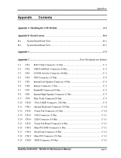
... C-6 C.10 CN10 VGA CARD Connector (242-Pin C-6 C.11 CN11 Internal Keyboard Connector (34-Pin C-10 C.12 CN12 Touch Pad Connector (12-Pin C-10 C.13 CN13 FAN Connector (3-Pin C-11 C.14 CN14 LED Connector (16-Pin C-11 C.15 CN15 Touch Pad Board Connector (6-Pin C-11 C.16 CN16 Mini PCI GND Connector (1-Pin... C-11 C.17 CN18 Stick Point Connector (8-Pin C-12 C.18 CN19 Mini PCI Connector (52-Pin C-12 C.19 CN20 ODD Connector (50-Pin C-13 Satellite A100/A105 / TECRA A7 Maintenance Manual App-iii
... C-6 C.10 CN10 VGA CARD Connector (242-Pin C-6 C.11 CN11 Internal Keyboard Connector (34-Pin C-10 C.12 CN12 Touch Pad Connector (12-Pin C-10 C.13 CN13 FAN Connector (3-Pin C-11 C.14 CN14 LED Connector (16-Pin C-11 C.15 CN15 Touch Pad Board Connector (6-Pin C-11 C.16 CN16 Mini PCI GND Connector (1-Pin... C-11 C.17 CN18 Stick Point Connector (8-Pin C-12 C.18 CN19 Mini PCI Connector (52-Pin C-12 C.19 CN20 ODD Connector (50-Pin C-13 Satellite A100/A105 / TECRA A7 Maintenance Manual App-iii
Maintenance Manual
Page 247
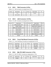
... 1 /PWR_OLED#_VCC' O 3 /PWR_OLED#' O 5 /PWR_BUF_BLED#_VCC' O 7 /SCAN_IN(0)' O 9 /SCAN_IN(3)' O 11 /SCAN_IN(5)' O 13 /MACHINE_ID0_DB' O 15 DGND' - Satellite A100/A105 / TECRA A7 Maintenance Manual C-11 Pin No. Signal Name I/O 2 /PWR_SWIN#_3' I 2 DGND - 3 FAN_TACH1' O C.14 CN14 LED Connector (16-Pin) Table C-14 LED...1 DGND' - - - - Signal Name I /O Pin No. C Pin Assignments C.13 CN13 FAN Connector (3-Pin) Table C-13 FAN Connector pin assignments (3-Pin) Pin No. Signal Name I /O Pin No. Appendices Apx. Signal Name I /O Pin No.
... 1 /PWR_OLED#_VCC' O 3 /PWR_OLED#' O 5 /PWR_BUF_BLED#_VCC' O 7 /SCAN_IN(0)' O 9 /SCAN_IN(3)' O 11 /SCAN_IN(5)' O 13 /MACHINE_ID0_DB' O 15 DGND' - Satellite A100/A105 / TECRA A7 Maintenance Manual C-11 Pin No. Signal Name I/O 2 /PWR_SWIN#_3' I 2 DGND - 3 FAN_TACH1' O C.14 CN14 LED Connector (16-Pin) Table C-14 LED...1 DGND' - - - - Signal Name I /O Pin No. C Pin Assignments C.13 CN13 FAN Connector (3-Pin) Table C-13 FAN Connector pin assignments (3-Pin) Pin No. Signal Name I /O Pin No. Appendices Apx. Signal Name I /O Pin No.


