
Cubase LE5 Quick Start Guide
Page 1
... LE 5 Help menu (and access the PDF manuals) for information about how to replace the user's manual for using the unit with Cubase LE 5. and other countries. •• Macintosh, Mac OS and Mac OS X are trademarks of their respective owners. TASCAM Cubase LE 5 1 Installing Cubase LE 5 1 Insert the Cubase LE 5 DVD-ROM into the DVD-ROM drive on the DVD-ROM. Select the...
... LE 5 Help menu (and access the PDF manuals) for information about how to replace the user's manual for using the unit with Cubase LE 5. and other countries. •• Macintosh, Mac OS and Mac OS X are trademarks of their respective owners. TASCAM Cubase LE 5 1 Installing Cubase LE 5 1 Insert the Cubase LE 5 DVD-ROM into the DVD-ROM drive on the DVD-ROM. Select the...

Cubase LE5 Quick Start Guide
Page 5
Preparation 1 Launch Cubase LE 5 and select Device Setup... The screens in the example below are from the Devices menu. from using a US-144MKII with Cubase LE 5 The settings in Cubase LE 5 are set to US-144MKII ports. Set the ASIO Driver item on the right to close the window. 3 When the following screen appears. 2 Click VST Audio System on the left side of the...
Preparation 1 Launch Cubase LE 5 and select Device Setup... The screens in the example below are from the Devices menu. from using a US-144MKII with Cubase LE 5 The settings in Cubase LE 5 are set to US-144MKII ports. Set the ASIO Driver item on the right to close the window. 3 When the following screen appears. 2 Click VST Audio System on the left side of the...

Cubase LE5 Quick Start Guide
Page 6
... the digital input and output should be available for use the digital input and output of the US-144MKII as inputs and outputs for the new project. A window appears that you to select a template for Cubase LE 5, add the digital input and output on the Input and Output tabs of the VST Connections window. •• Click the Add Bus button. •• When the following dialog appears, set...
... the digital input and output should be available for use the digital input and output of the US-144MKII as inputs and outputs for the new project. A window appears that you to select a template for Cubase LE 5, add the digital input and output on the Input and Output tabs of the VST Connections window. •• Click the Add Bus button. •• When the following dialog appears, set...

Cubase LE5 Quick Start Guide
Page 10
... the EQ section for the channel in the channel display and by the input display, which should say "Stereo In" or something similar, when the channel is enabled. Before you need. A3. I think I have a stereo track, select Project menu > Add track > Audio and create the number of the track is selected. If the project does not have configured the input settings properly, but it does...
... the EQ section for the channel in the channel display and by the input display, which should say "Stereo In" or something similar, when the channel is enabled. Before you need. A3. I think I have a stereo track, select Project menu > Add track > Audio and create the number of the track is selected. If the project does not have configured the input settings properly, but it does...

Cubase LE5 Quick Start Guide
Page 11
... LE 5 11 The default setting is being input, the signal indicator of the audio interface will light up green. Q6. Could the sampling rate of the audio interface is obviously different. To specify the sampling rate, choose Project Settings from the beginning. Make sure that the connections are correct. Q5. I burned a CD using the WAV file I cannot set the locator region...
... LE 5 11 The default setting is being input, the signal indicator of the audio interface will light up green. Q6. Could the sampling rate of the audio interface is obviously different. To specify the sampling rate, choose Project Settings from the beginning. Make sure that the connections are correct. Q5. I burned a CD using the WAV file I cannot set the locator region...
US-2000 Owner's Manual
Page 2
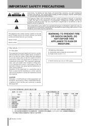
... BACK). Model number Serial number For U.S.A. This equipment generates, uses, and can radiate radio frequency energy and, if not installed and used in accordance with the instruction manual, may be required to provide reasonable protection against harmful interference when the equipment is likely to cause harmful interference in a commercial environment. NO USER-SERVICEABLE PARTS INSIDE. This appliance has a serial number located on 120V supply. 2 TASCAM US-2000
... BACK). Model number Serial number For U.S.A. This equipment generates, uses, and can radiate radio frequency energy and, if not installed and used in accordance with the instruction manual, may be required to provide reasonable protection against harmful interference when the equipment is likely to cause harmful interference in a commercial environment. NO USER-SERVICEABLE PARTS INSIDE. This appliance has a serial number located on 120V supply. 2 TASCAM US-2000
US-2000 Owner's Manual
Page 3
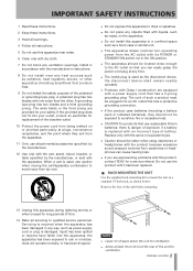
... when unused for ventilation. 3 TASCAM US-2000 IMPORTANT SAFETY INSTRUCTIONS 1 Read these instructions. 2 Keep these instructions. 3 Heed all warnings. 4 Follow all servicing to qualified service personnel. When a cart is replaced with a power supply cord that has a 3-prong grounding plug. Servicing is required when the apparatus has been damaged in any way, such as power-supply cord or plug is used as shown below. The wide blade...
... when unused for ventilation. 3 TASCAM US-2000 IMPORTANT SAFETY INSTRUCTIONS 1 Read these instructions. 2 Keep these instructions. 3 Heed all warnings. 4 Follow all servicing to qualified service personnel. When a cart is replaced with a power supply cord that has a 3-prong grounding plug. Servicing is required when the apparatus has been damaged in any way, such as power-supply cord or plug is used as shown below. The wide blade...
US-2000 Owner's Manual
Page 4
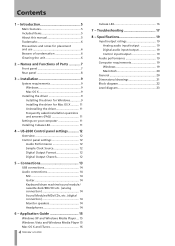
... your computer 11 Installing Cubase LE4 11 4 − US-2000 Control panel settings............12 Overview 12 Control panel settings 12 Audio Performance 12 Sample Clock Source 12 Digital Output Format 12 Digital Output Chanels 12 5 − Connections 13 USB connections 14 Audio connections 14 Mic 14 Guitar 14 Keyboard/drum machine/sound module/ cassette deck/MD/CD etc. (analog connection 14 Sound Modules/MDs/CDs, etc. (digital connection 14 Monitor speakers 14 Headphones 14 6 - Application Guide 15 Windows XP and...
... your computer 11 Installing Cubase LE4 11 4 − US-2000 Control panel settings............12 Overview 12 Control panel settings 12 Audio Performance 12 Sample Clock Source 12 Digital Output Format 12 Digital Output Chanels 12 5 − Connections 13 USB connections 14 Audio connections 14 Mic 14 Guitar 14 Keyboard/drum machine/sound module/ cassette deck/MD/CD etc. (analog connection 14 Sound Modules/MDs/CDs, etc. (digital connection 14 Monitor speakers 14 Headphones 14 6 - Application Guide 15 Windows XP and...

US-2000 Owner's Manual
Page 5
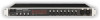
... owner's manual that should be monitored individually in mono or in stereo as pairs of channels • Outputs include 4 balanced line, a balanced pair for monitors, digital and headphone • S/PDIF or AES/EBU selectable digital output • 5-dot meter for every input and output • Direct monitoring function allows input monitoring without latency • In addition to properly set up and connect the unit, as well as the operation of the TASCAM US-2000 USB 2.0 Audio...
... owner's manual that should be monitored individually in mono or in stereo as pairs of channels • Outputs include 4 balanced line, a balanced pair for monitors, digital and headphone • S/PDIF or AES/EBU selectable digital output • 5-dot meter for every input and output • Direct monitoring function allows input monitoring without latency • In addition to properly set up and connect the unit, as well as the operation of the TASCAM US-2000 USB 2.0 Audio...

US-2000 Owner's Manual
Page 6
...generating electrical device such as they could damage the surface. 6 TASCAM US-2000 ASIO is a trademark of Steinberg Media Technologies GmbH. • ...power amplifier. Cleaning the unit To clean the unit, wipe it gently with chemical cleaning cloths, benzene, paint thinner, ethyl alcohol or other chemical agents to a warm place, or used after a sudden temperature change...level position for correct operation. • Do not place any object on the unit for heat dissipation. • Avoid installing this occurs, let the player sit for one or two hours at the new room temperature before using...
...generating electrical device such as they could damage the surface. 6 TASCAM US-2000 ASIO is a trademark of Steinberg Media Technologies GmbH. • ...power amplifier. Cleaning the unit To clean the unit, wipe it gently with chemical cleaning cloths, benzene, paint thinner, ethyl alcohol or other chemical agents to a warm place, or used after a sudden temperature change...level position for correct operation. • Do not place any object on the unit for heat dissipation. • Avoid installing this occurs, let the player sit for one or two hours at the new room temperature before using...

US-2000 Owner's Manual
Page 7
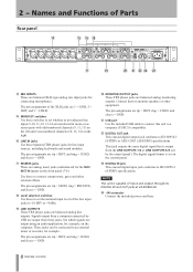
... way to the mic input jacks in use this to adjust the level of MIC INPUTS 1-8 independently. The pin assignments of the XLR jacks are analog mic/instrument inputs that have mini-plugs. Front panel 2 − Names and Functions of Parts 11POWER switch Use to turn the output volume down using the PHONES and MONITOR knobs. q MONITOR switches Use these switches to set whether or not +48 V phantom power is provided to the left and even-numbered channels (2, 4, 6, 8) on the mic, loud noises might...
... way to the mic input jacks in use this to adjust the level of MIC INPUTS 1-8 independently. The pin assignments of the XLR jacks are analog mic/instrument inputs that have mini-plugs. Front panel 2 − Names and Functions of Parts 11POWER switch Use to turn the output volume down using the PHONES and MONITOR knobs. q MONITOR switches Use these switches to set whether or not +48 V phantom power is provided to the left and even-numbered channels (2, 4, 6, 8) on the mic, loud noises might...
US-2000 Owner's Manual
Page 8
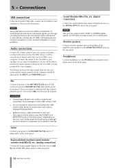
... pin assignments are balanced analog line outputs. i1Level selection switches Use these to monitor speakers or other external effects. Set which signals are output using an audio application, for connecting microphones. NOTE This unit is set the nominal input level of the line input jacks to IEC60958-3 (S/PDIF) or AES3-2003 (AES/EBU) specifications. 2 − Names and Functions of Parts Rear panel r1MIC INPUTS These are balanced XLR-type analog mic input jacks for example, on the control panel. d1DIGITAL IN jack This coaxial digital input jack conforms to...
... pin assignments are balanced analog line outputs. i1Level selection switches Use these to monitor speakers or other external effects. Set which signals are output using an audio application, for connecting microphones. NOTE This unit is set the nominal input level of the line input jacks to IEC60958-3 (S/PDIF) or AES3-2003 (AES/EBU) specifications. 2 − Names and Functions of Parts Rear panel r1MIC INPUTS These are balanced XLR-type analog mic input jacks for example, on the control panel. d1DIGITAL IN jack This coaxial digital input jack conforms to...
US-2000 Owner's Manual
Page 9
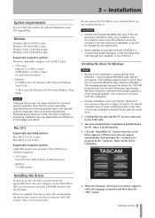
... that has not received Windows Logo testing is an easy process using the CD-ROM included with the US-2000. Installation may vary depending on the driver CD-ROM.) 4 When the language selection screen (below , this software ... has not passed Windows Logo testing" will install it and the software cannot be aware that "this is installed. Please be installed. Mac OS X Supported operating system: Mac...
... that has not received Windows Logo testing is an easy process using the CD-ROM included with the US-2000. Installation may vary depending on the driver CD-ROM.) 4 When the language selection screen (below , this software ... has not passed Windows Logo testing" will install it and the software cannot be aware that "this is installed. Please be installed. Mac OS X Supported operating system: Mac...
US-2000 Owner's Manual
Page 11
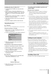
... "Remove the driver". 3 Follow the instructions on the screen. Select "Install Driver," and follow the instructions on the screen for the disc drive might be disabled. Using the Installation CD-ROM: 1 Follow steps 1 to help you set up your computer Here are running other applications. Using Windows "Add or Remove Programs" : 1 Open the "Control Panel" from the "Start" menu. 2 Double click on "Add or Remove programs". 3 Select "US-2000 driver" from the TASCAM...
... "Remove the driver". 3 Follow the instructions on the screen. Select "Install Driver," and follow the instructions on the screen for the disc drive might be disabled. Using the Installation CD-ROM: 1 Follow steps 1 to help you set up your computer Here are running other applications. Using Windows "Add or Remove Programs" : 1 Open the "Control Panel" from the "Start" menu. 2 Double click on "Add or Remove programs". 3 Select "US-2000 driver" from the TASCAM...

US-2000 Owner's Manual
Page 12
... your system. Digital Output Chanels The DIGITAL OUT jack outputs either digital signals of signals to output using digital input, set this to "Automatic." You should select the buffer size that will produce greater delay when monitoring the audio signal. If no "Audio Performance" setting on the Mac OS X version of the US-2000 Control Panel, the "Audio Performance" setting permits you make various settings for the US-2000's functionality. A smaller buffer size will reduce the delay when monitoring the audio signal, but will...
... your system. Digital Output Chanels The DIGITAL OUT jack outputs either digital signals of signals to output using digital input, set this to "Automatic." You should select the buffer size that will produce greater delay when monitoring the audio signal. If no "Audio Performance" setting on the Mac OS X version of the US-2000 Control Panel, the "Audio Performance" setting permits you make various settings for the US-2000's functionality. A smaller buffer size will reduce the delay when monitoring the audio signal, but will...
US-2000 Owner's Manual
Page 14
... (7-8) jack (1/4" phone jack) on the rear panel. Connect the output of the US-2000 to your mics to the USB bus used by the US-2000. Mic Connect your speakers (via USB to the PHONES jack (standard stereo phone jack) on the front pannel. Sound Modules/MDs/CDs, etc. (digital connection) Connect the digital inputs and outputs of your computer as shown in the audio signal, we strongly recommend that requires phantom power, turn the output volume down using the PHONES and MONITOR...
... (7-8) jack (1/4" phone jack) on the rear panel. Connect the output of the US-2000 to your mics to the USB bus used by the US-2000. Mic Connect your speakers (via USB to the PHONES jack (standard stereo phone jack) on the front pannel. Sound Modules/MDs/CDs, etc. (digital connection) Connect the digital inputs and outputs of your computer as shown in the audio signal, we strongly recommend that requires phantom power, turn the output volume down using the PHONES and MONITOR...

US-2000 Owner's Manual
Page 15
..." menu. 2 Open "Sounds and Audio Devices." Windows XP and Windows Media Player 1 Close all applications and then open the "Control Panel" from the "Start" menu. 2 Open "Sound." 6 - Application Guide In this unit, but no sound will appear. 3 Click the "Playback" tab, click "Speakers TASCAM US-2000" and click the "Set Default" button. This moves the green check mark to "Speakers TASCAM US-2000." 4 Click "OK." 5 Start Windows Media Player, select an audio...
..." menu. 2 Open "Sounds and Audio Devices." Windows XP and Windows Media Player 1 Close all applications and then open the "Control Panel" from the "Start" menu. 2 Open "Sound." 6 - Application Guide In this unit, but no sound will appear. 3 Click the "Playback" tab, click "Speakers TASCAM US-2000" and click the "Set Default" button. This moves the green check mark to "Speakers TASCAM US-2000." 4 Click "OK." 5 Start Windows Media Player, select an audio...
US-2000 Owner's Manual
Page 17
... the USB indicator is noise. Methods to reduce the load on the application you are different from the Apple menu. 2 Open "Sound." 3 From the "Output" tab, select "US-2000: Output." Troubleshooting Please read this manual for the application that the USB cable is failing. Please confirm the following settings, sound will be set the "Default device:" for "Sound playback" and "Sound recording" to use : ª Installation is properly connected. 7 -
... the USB indicator is noise. Methods to reduce the load on the application you are different from the Apple menu. 2 Open "Sound." 3 From the "Output" tab, select "US-2000: Output." Troubleshooting Please read this manual for the application that the USB cable is failing. Please confirm the following settings, sound will be set the "Default device:" for "Sound playback" and "Sound recording" to use : ª Installation is properly connected. 7 -

US-2000 Owner's Manual
Page 18
Troubleshooting break up and noise. from the Apple menu and select "Energy Saver." 2 Click the "Sleep" tab. 3 Set "Put the computer to sleep when it is inactive for :" to sleep when the computer is available, set 18 TASCAM US-2000 it is not supported by TASCAM. If a "Processor performance" setting is inactive for :" to "Never." 4 Set "Put the display(s) to "Never." 5 Click...
Troubleshooting break up and noise. from the Apple menu and select "Energy Saver." 2 Click the "Sleep" tab. 3 Set "Put the computer to sleep when it is inactive for :" to sleep when the computer is available, set 18 TASCAM US-2000 it is not supported by TASCAM. If a "Processor performance" setting is inactive for :" to "Never." 4 Set "Put the display(s) to "Never." 5 Click...

US-2000 Owner's Manual
Page 19
... output level: +14 dBu Input impedance: 10 kΩ Nominal input level 8 - Specifications -2 dBu Maximum input level: +14 dBu PHONES jack Connector: 6.3 mm (1/4") Standard Stereo phone jack Maximum output level: 100 mW + 100 mW or more (THD + N less than 1%, 32Ω load) Digital audio input/output DIGITAL IN (COAXIAL) terminal Connector: RCA pin jack Compatible signal format: IEC60958-3 (S/PDIF) DIGITAL OUT (COAXIAL) terminal Connector: RCA pin jack Compatible signal format: IEC60958-3 (S/PDIF) or AES3-2003 (AES/EBU), selectable using control panel Control input/output...
... output level: +14 dBu Input impedance: 10 kΩ Nominal input level 8 - Specifications -2 dBu Maximum input level: +14 dBu PHONES jack Connector: 6.3 mm (1/4") Standard Stereo phone jack Maximum output level: 100 mW + 100 mW or more (THD + N less than 1%, 32Ω load) Digital audio input/output DIGITAL IN (COAXIAL) terminal Connector: RCA pin jack Compatible signal format: IEC60958-3 (S/PDIF) DIGITAL OUT (COAXIAL) terminal Connector: RCA pin jack Compatible signal format: IEC60958-3 (S/PDIF) or AES3-2003 (AES/EBU), selectable using control panel Control input/output...


