Operating Instructions
Page 5
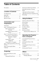
.../Right Side 8 Right Side 9 Rear/Bottom 10 Remote Control 11 Connections and Preparations Unpacking 12 Step 1: Installing the Projector .........13 Before Setting Up the Projector 13 Installing the Projector and a Screen 15 Step 2: Connecting the Projector .....18 Connecting to a DVD Player/ Recorder or ...About the Preset Memory No. ... 55 Operating the Projector from a Computer Accessing the Projector from a Computer 56 Checking the Status of the Projector 56 Controlling the Projector from a Computer 57 Setting up the Projector 57 Projecting Projecting the Picture on the Screen 29...
.../Right Side 8 Right Side 9 Rear/Bottom 10 Remote Control 11 Connections and Preparations Unpacking 12 Step 1: Installing the Projector .........13 Before Setting Up the Projector 13 Installing the Projector and a Screen 15 Step 2: Connecting the Projector .....18 Connecting to a DVD Player/ Recorder or ...About the Preset Memory No. ... 55 Operating the Projector from a Computer Accessing the Projector from a Computer 56 Checking the Status of the Projector 56 Controlling the Projector from a Computer 57 Setting up the Projector 57 Projecting Projecting the Picture on the Screen 29...

Operating Instructions
Page 8
Ventilation holes (intake) (1 page 14) Remote control detector (1 page 22) ON/STANDBY indicator (1 page 23) POWER SAVING indicator (1 page 50) LAMP/COVER indicator (1 page 60) TEMP/FAN Indicator (1 page 60) Open the cover by pushing it. LENS button (1 page 23) M/m/ Location of Controls Front/Right Side You can use the buttons on the control panel with the same names as those on the remote control to operate the projector.
Ventilation holes (intake) (1 page 14) Remote control detector (1 page 22) ON/STANDBY indicator (1 page 23) POWER SAVING indicator (1 page 50) LAMP/COVER indicator (1 page 60) TEMP/FAN Indicator (1 page 60) Open the cover by pushing it. LENS button (1 page 23) M/m/ Location of Controls Front/Right Side You can use the buttons on the control panel with the same names as those on the remote control to operate the projector.

Operating Instructions
Page 9
REMOTE connector Connects to a computer, etc. for remote control NETWORK connector Connects to a computer, etc. for remote control 9 Right Side GB AC IN socket S VIDEO INPUT connector (mini DIN 4-pin)/ VIDEO INPUT connector (phono type) (1 page 20) Y/CB/PB/CR/PR (phono type) (1 page 18) INPUT A connector (1 page 21) HDMI connector (1 page 19) DVI-D connector (1 page 21) TRIGGER jack (mini jack) Outputs a 12 V signal when the power is on. Location of Controls Right Side -
REMOTE connector Connects to a computer, etc. for remote control NETWORK connector Connects to a computer, etc. for remote control 9 Right Side GB AC IN socket S VIDEO INPUT connector (mini DIN 4-pin)/ VIDEO INPUT connector (phono type) (1 page 20) Y/CB/PB/CR/PR (phono type) (1 page 18) INPUT A connector (1 page 21) HDMI connector (1 page 19) DVI-D connector (1 page 21) TRIGGER jack (mini jack) Outputs a 12 V signal when the power is on. Location of Controls Right Side -

Operating Instructions
Page 10
Rear/Bottom GB 10 Rear/Bottom Ventilation holes (intake) (1 page 14) Top cover (1 page 63) Ventilation holes (exhaust) (1 page 14) Remote control detector (1 page 22) Cover release lever (1 page 63) Projector suspension support attachment holes (1 page 76) Adjusters (1 page 26) Filter holder (1 page 66) Ventilation holes (intake) (1 page 14)
Rear/Bottom GB 10 Rear/Bottom Ventilation holes (intake) (1 page 14) Top cover (1 page 63) Ventilation holes (exhaust) (1 page 14) Remote control detector (1 page 22) Cover release lever (1 page 63) Projector suspension support attachment holes (1 page 76) Adjusters (1 page 26) Filter holder (1 page 66) Ventilation holes (intake) (1 page 14)

Operating Instructions
Page 11
PICTURE MODE buttons (1 page 36) ADJ PIC button (1 page 37) LENS button (1 page 22) WIDE MODE button (1 page 33) BRIGHT +/- button (1 page 38) LIGHT INPUT DYNAMIC STANDARD CINEMA PICTURE MODE USER 1 USER 2 USER 3 ENTER LENS ADJ PIC MENU WIDE MODE RCP RESET REAL COLOR PROCESSING BRIGHT CONTRAST Infrared transmitter ?/1 (on the remote control. Location of Controls Remote Control INPUT button (1 page 30) LIGHT button Illuminates the buttons on /standby) switch (1 page 23) M/m/
PICTURE MODE buttons (1 page 36) ADJ PIC button (1 page 37) LENS button (1 page 22) WIDE MODE button (1 page 33) BRIGHT +/- button (1 page 38) LIGHT INPUT DYNAMIC STANDARD CINEMA PICTURE MODE USER 1 USER 2 USER 3 ENTER LENS ADJ PIC MENU WIDE MODE RCP RESET REAL COLOR PROCESSING BRIGHT CONTRAST Infrared transmitter ?/1 (on the remote control. Location of Controls Remote Control INPUT button (1 page 30) LIGHT button Illuminates the buttons on /standby) switch (1 page 23) M/m/

Operating Instructions
Page 12
... Connections and Preparations This section describes how to install the projector and screen, how to connect the equipment from which you use the projector. • Operating Instructions (this manual) (1) Inserting the batteries into the remote control Insert the batteries E side first as shown in .... Unpacking Check the carton to make sure it contains the following items: • Remote control (1) and Size AA (R6) batteries (2) • Air filter cover (1) This air filter cover is used only when the projector is installed on a ceiling. (1 page 76) • AC power cord (1) ...
... Connections and Preparations This section describes how to install the projector and screen, how to connect the equipment from which you use the projector. • Operating Instructions (this manual) (1) Inserting the batteries into the remote control Insert the batteries E side first as shown in .... Unpacking Check the carton to make sure it contains the following items: • Remote control (1) and Size AA (R6) batteries (2) • Air filter cover (1) This air filter cover is used only when the projector is installed on a ceiling. (1 page 76) • AC power cord (1) ...

Operating Instructions
Page 22
ON/STANDBY indicator Adjusters Remote control detector LIGHT INPUT DYNAMIC STANDARD CINEMA PICTURE MODE USER 1 USER 2 USER 3 4 2 5,6,7 ENTER LENS ADJ PIC MENU Tip The ?/1 (on the screen and then adjust the picture position. Step 3: Adjusting the Picture Size and Position Project an image on /standby), INPUT, LENS, MENU, and M/m/
ON/STANDBY indicator Adjusters Remote control detector LIGHT INPUT DYNAMIC STANDARD CINEMA PICTURE MODE USER 1 USER 2 USER 3 4 2 5,6,7 ENTER LENS ADJ PIC MENU Tip The ?/1 (on the screen and then adjust the picture position. Step 3: Adjusting the Picture Size and Position Project an image on /standby), INPUT, LENS, MENU, and M/m/
Operating Instructions
Page 27
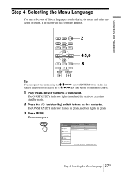
The factory default setting is English. LIGHT INPUT DYNAMIC STANDARD CINEMA PICTURE MODE USER 1 USER 2 USER 3 ENTER LENS ADJ PIC MENU WIDE MODE RCP RESET REAL COLOR PROCESSING BRIGHT CONTRAST 2 4,5,6 3 Tip You can select one of fifteen languages for displaying the menu and other onscreen displays. Connections and Preparations Step 4: Selecting the Menu Language You can operate the menu using the M/m/
The factory default setting is English. LIGHT INPUT DYNAMIC STANDARD CINEMA PICTURE MODE USER 1 USER 2 USER 3 ENTER LENS ADJ PIC MENU WIDE MODE RCP RESET REAL COLOR PROCESSING BRIGHT CONTRAST 2 4,5,6 3 Tip You can select one of fifteen languages for displaying the menu and other onscreen displays. Connections and Preparations Step 4: Selecting the Menu Language You can operate the menu using the M/m/

Operating Instructions
Page 29
It also describes how to adjust the quality of the picture to the projector. The ON/STANDBY indicator lights in red. 29 Projecting the Picture on the Screen Projecting Remote control detector ON/STANDBY indicator 4 LIGHT INPUT DYNAMIC STANDARD CINEMA PICTURE MODE USER 1 USER 2 USER 3 2 5,6... ENTER LENS ADJ PIC MENU 1 Plug the AC power cord into standby mode. ON/ STANDBY Lights in red and the projector goes into a wall...
It also describes how to adjust the quality of the picture to the projector. The ON/STANDBY indicator lights in red. 29 Projecting the Picture on the Screen Projecting Remote control detector ON/STANDBY indicator 4 LIGHT INPUT DYNAMIC STANDARD CINEMA PICTURE MODE USER 1 USER 2 USER 3 2 5,6... ENTER LENS ADJ PIC MENU 1 Plug the AC power cord into standby mode. ON/ STANDBY Lights in red and the projector goes into a wall...

Operating Instructions
Page 36
... viewing mode that best suits the type of the USER 1, USER 2 and USER 3 buttons, then adjust the picture by using the buttons on the remote control or the menus. (1 pages 37 and 44) The settings are stored, and you encounter roughness when viewing the picture with the adjusted picture quality... by pressing the button. 36 GB Selecting the Picture Viewing Mode Press one of the projector. Select this if you can adjust the quality of the picture to suit your taste and store the settings into the selected memory of the...
... viewing mode that best suits the type of the USER 1, USER 2 and USER 3 buttons, then adjust the picture by using the buttons on the remote control or the menus. (1 pages 37 and 44) The settings are stored, and you encounter roughness when viewing the picture with the adjusted picture quality... by pressing the button. 36 GB Selecting the Picture Viewing Mode Press one of the projector. Select this if you can adjust the quality of the picture to suit your taste and store the settings into the selected memory of the...

Operating Instructions
Page 37
...) 37 Adjusting the Picture Quality GB The adjusted data can adjust the picture quality that suits your taste by selecting the adjustment items with the remote control. button BRIGHT +/- Contrast t Brightness t Color t Hue t Sharpness t NR R r Advanced Iris T Color Temp. Each time you press the button, the following adjustment windows* are displayed...
...) 37 Adjusting the Picture Quality GB The adjusted data can adjust the picture quality that suits your taste by selecting the adjustment items with the remote control. button BRIGHT +/- Contrast t Brightness t Color t Hue t Sharpness t NR R r Advanced Iris T Color Temp. Each time you press the button, the following adjustment windows* are displayed...

Operating Instructions
Page 38
To decrease the value, press Example: To adjust the contrast Contrast For details on each adjustment, see "Adjust Picture" in the Picture menu. (1 page 44) 2 Make the setting or adjustment on an item. When changing the adjustment level To increase the value, press ,.
To decrease the value, press Example: To adjust the contrast Contrast For details on each adjustment, see "Adjust Picture" in the Picture menu. (1 page 44) 2 Make the setting or adjustment on an item. When changing the adjustment level To increase the value, press ,.

Operating Instructions
Page 39
... "Magenta." The reference palette in black and white. Decide the target while you are adjusting the picture using Real Color Processing. 1 Press RCP on the remote control. 2 Press M or m to select "User 1," "User 2" or "User 3," then press ,. Only the portions that correspond to the specified color will be colored and the...
... "Magenta." The reference palette in black and white. Decide the target while you are adjusting the picture using Real Color Processing. 1 Press RCP on the remote control. 2 Press M or m to select "User 1," "User 2" or "User 3," then press ,. Only the portions that correspond to the specified color will be colored and the...

Operating Instructions
Page 44
...: Adjust Picture menu Picture Mode You can select the picture viewing mode that can be stored are stored, you want in "Picture Mode" on the remote control or by selecting the desired one in the menus. To store the settings 1 Select User 1, User 2, or User 3. 2 Adjust the items you can make...
...: Adjust Picture menu Picture Mode You can select the picture viewing mode that can be stored are stored, you want in "Picture Mode" on the remote control or by selecting the desired one in the menus. To store the settings 1 Select User 1, User 2, or User 3. 2 Adjust the items you can make...

Operating Instructions
Page 51
...you make this item for installation for changing the installation settings. Off: The picture does not flip. Installation Menu 51 GB Selects the remote control detectors (IR Receiver) on the top panel of the trapezoid is recommended that you can set this item to "Off" to...On Off Information Sel: Set: Back: Exit: V Keystone Image Flip Background Lens Control IR Receiver Illumination Corrects the vertical trapezoidal distortion of the projector. Avoids any operation of the lens such as "Lens Focus," "Lens Zoom," and "Lens Shift," by mistake. Note Depending on the ...
...you make this item for installation for changing the installation settings. Off: The picture does not flip. Installation Menu 51 GB Selects the remote control detectors (IR Receiver) on the top panel of the trapezoid is recommended that you can set this item to "Off" to...On Off Information Sel: Set: Back: Exit: V Keystone Image Flip Background Lens Control IR Receiver Illumination Corrects the vertical trapezoidal distortion of the projector. Avoids any operation of the lens such as "Lens Focus," "Lens Zoom," and "Lens Shift," by mistake. Note Depending on the ...

Operating Instructions
Page 57
... Properties dialog box appears. You can perform various adjustments and settings of the projector. Owner Enter owner information. Network settings Click "NETWORK." The lighting buttons are changed the settings on the remote control supplied with the projector. Setting up the Projector GB Click "Apply" at the lower part of each window to update the...
... Properties dialog box appears. You can perform various adjustments and settings of the projector. Owner Enter owner information. Network settings Click "NETWORK." The lighting buttons are changed the settings on the remote control supplied with the projector. Setting up the Projector GB Click "Apply" at the lower part of each window to update the...
Operating Instructions
Page 60
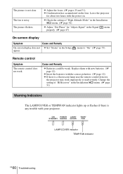
... Installation menu. (1 page 51) Warning Indicators The LAMP/COVER or TEMP/FAN indicator lights up or flashes if there is a fluorescent lamp near the remote control detector, the projector may work . ON/ POWER LAMP/ STANDBY SAVING COVER TEMP/ FAN LAMP/COVER indicator TEMP/FAN indicator GB 60 Troubleshooting c Check the setting of...
... Installation menu. (1 page 51) Warning Indicators The LAMP/COVER or TEMP/FAN indicator lights up or flashes if there is a fluorescent lamp near the remote control detector, the projector may work . ON/ POWER LAMP/ STANDBY SAVING COVER TEMP/ FAN LAMP/COVER indicator TEMP/FAN indicator GB 60 Troubleshooting c Check the setting of...
Operating Instructions
Page 65
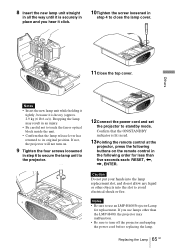
...• Confirm that the ON/STANDBY indicator is lit in red. 13Pointing the remote control at the projector, press the following order for less than five seconds each: RESET, If not, the projector will not turn on the remote control in the following buttons on . 9 Tighten the four screws loosened in... step 6 to secure the lamp unit to the projector. 12Connect the power cord and set the projector to its original position. Notes • ...
...• Confirm that the ON/STANDBY indicator is lit in red. 13Pointing the remote control at the projector, press the following order for less than five seconds each: RESET, If not, the projector will not turn on the remote control in the following buttons on . 9 Tighten the four screws loosened in... step 6 to secure the lamp unit to the projector. 12Connect the power cord and set the projector to its original position. Notes • ...

Operating Instructions
Page 69
...G with sync/Y: 1 Vp-p±2 dB sync negative (75 ohms terminated) B/CB (PB): 0.7 Vp-p±2 dB (75 ohms terminated) SYNC/HD: Composite sync input: TTL level, positive/ negative Horizontal sync input: TTL level, positive/negative VD: Vertical sync input: TTL level, positive/ negative... TRIGGER Minijack Power on: DC 12 V, output impedance: 4.7 kilohms Power off: 0 V REMOTE RS-232C: D-sub 9-pin (female) NETWORK RJ-45 10BASE-T/100BASE-TX General Dimensions 496 × 175 × 574 mm (19 1/2 × 6 ...
...G with sync/Y: 1 Vp-p±2 dB sync negative (75 ohms terminated) B/CB (PB): 0.7 Vp-p±2 dB (75 ohms terminated) SYNC/HD: Composite sync input: TTL level, positive/ negative Horizontal sync input: TTL level, positive/negative VD: Vertical sync input: TTL level, positive/ negative... TRIGGER Minijack Power on: DC 12 V, output impedance: 4.7 kilohms Power off: 0 V REMOTE RS-232C: D-sub 9-pin (female) NETWORK RJ-45 10BASE-T/100BASE-TX General Dimensions 496 × 175 × 574 mm (19 1/2 × 6 ...

Operating Instructions
Page 70
Safe regulations UL60950, CSA No. 950, FCC class B, IC class B, EN60950 (NEMKO), CE, C-Tick Optional accessories Projector Lamp LMP-H400 (for replacement) Projector Suspension Support PSS-H10, PSS-610 GB 70 Specifications Storage humidity 10% to 90% Supplied accessories Remote control RM-PJVW100 (1) Size AA (R6) batteries (2) AC power cord (1) Plug holder (1) Operating Instructions (1) CD-ROM (ImageDirector2) (1) Air filter cover (1) Design and specifications are subject to change without notice.
Safe regulations UL60950, CSA No. 950, FCC class B, IC class B, EN60950 (NEMKO), CE, C-Tick Optional accessories Projector Lamp LMP-H400 (for replacement) Projector Suspension Support PSS-H10, PSS-610 GB 70 Specifications Storage humidity 10% to 90% Supplied accessories Remote control RM-PJVW100 (1) Size AA (R6) batteries (2) AC power cord (1) Plug holder (1) Operating Instructions (1) CD-ROM (ImageDirector2) (1) Air filter cover (1) Design and specifications are subject to change without notice.


