Operating Instructions
Page 7
... the lens while the lamp is on. • Do not place your hand or objects near the ventilation holes - If the floor and walls are not of light-reflecting material. On LCD projector The LCD projector is recommended. Never pull the cord itself has been turned off the power with the 1 key on the Remote Commander or the I / 1 key on the control panel, do...
... the lens while the lamp is on. • Do not place your hand or objects near the ventilation holes - If the floor and walls are not of light-reflecting material. On LCD projector The LCD projector is recommended. Never pull the cord itself has been turned off the power with the 1 key on the Remote Commander or the I / 1 key on the control panel, do...
Operating Instructions
Page 8
... Screen This projector utilizes a 16:9 aspect ratio LCD panel, allowing seven screen modes (ZOOM, FULL, SUBTITLE, WIDE ZOOM, etc.) using all panel pixels (1366 × 768). The projector's white color goes with any setting from the fan to the exhaust opening at a wide angle. These include DRC-MF (Digital Reality Creation Multifunction) (Sony's proprietary high-quality image technology); 3-D Gamma Correction, providing excellent uniformity; The user can directly recall any color (ceilings, walls, etc.). High-adaptability...
... Screen This projector utilizes a 16:9 aspect ratio LCD panel, allowing seven screen modes (ZOOM, FULL, SUBTITLE, WIDE ZOOM, etc.) using all panel pixels (1366 × 768). The projector's white color goes with any setting from the fan to the exhaust opening at a wide angle. These include DRC-MF (Digital Reality Creation Multifunction) (Sony's proprietary high-quality image technology); 3-D Gamma Correction, providing excellent uniformity; The user can directly recall any color (ceilings, walls, etc.). High-adaptability...
Operating Instructions
Page 9
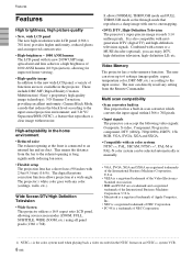
...). 8 Control panel For details, see "Cleaning the Air Filter" on the out of the picture. 2 Focus ring Adjusts the picture focus. 3 Ventilation holes (exhaust) 4 Lens Remove the lens cap before projection. 5 Front remote control detector (SIRCS receiver) 6 Adjusters When a picture is projected on page 35 (GB). For details, see "Control panel" on page 11 (GB). 9 AC IN socket Connects the supplied AC power cord. 0 Rear remote control detector (SIRCS receiver) qa Lamp cover qs Rear adjusters qd Ventilation holes (intake)/air filter cover...
...). 8 Control panel For details, see "Cleaning the Air Filter" on the out of the picture. 2 Focus ring Adjusts the picture focus. 3 Ventilation holes (exhaust) 4 Lens Remove the lens cap before projection. 5 Front remote control detector (SIRCS receiver) 6 Adjusters When a picture is projected on page 35 (GB). For details, see "Control panel" on page 11 (GB). 9 AC IN socket Connects the supplied AC power cord. 0 Rear remote control detector (SIRCS receiver) qa Lamp cover qs Rear adjusters qd Ventilation holes (intake)/air filter cover...
Operating Instructions
Page 11
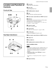
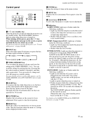
... turning off when the projector is turned on and off the power, press the I / 1 (on / standby) key Turns the projector on . The light will be displayed in orange. Control panel 0 LAMP/ COVER TEMP/ FAN POWER SAVING ON/ STANDBY MENU PATTERN ENTER RESET LIGHT INPUT VIDEO MEMORY 1 2 3 9 8765 4 1 I / 1 key twice following the message on the screen for about one second. The ON/STANDBY indicator lights in green when the power is in the VIDEO MEMORY 1 to turn off automatically if no keys are operated...
... turning off when the projector is turned on and off the power, press the I / 1 (on / standby) key Turns the projector on . The light will be displayed in orange. Control panel 0 LAMP/ COVER TEMP/ FAN POWER SAVING ON/ STANDBY MENU PATTERN ENTER RESET LIGHT INPUT VIDEO MEMORY 1 2 3 9 8765 4 1 I / 1 key twice following the message on the screen for about one second. The ON/STANDBY indicator lights in green when the power is in the VIDEO MEMORY 1 to turn off automatically if no keys are operated...

Operating Instructions
Page 13
Location and Function of Controls 4 VIDEO MEMORY keys You can store an image setting to one of equipment connected to the INPUT B connectors. Remote Commander The keys which have the same names as on the projector. (It is assumed that the projector is in the Stand-by pressing the appropriate key. VIDEO: Selects the signal of the VIDEO MEMORY keys (1 - 6), and you can control a connected computer using the...
Location and Function of Controls 4 VIDEO MEMORY keys You can store an image setting to one of equipment connected to the INPUT B connectors. Remote Commander The keys which have the same names as on the projector. (It is assumed that the projector is in the Stand-by pressing the appropriate key. VIDEO: Selects the signal of the VIDEO MEMORY keys (1 - 6), and you can control a connected computer using the...
Operating Instructions
Page 14
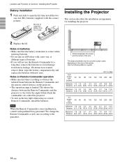
... on Remote Commander operation • Make sure that the battery orientation is , the wider the angle within which the commander can control the projector. • To turn on the size of the lens The distance between the lens and the screen varies depending on the key light when using as a wired Remote Commander, install the batteries. Distance between the screen and the center of the screen. We change the Remote Commander as a guide. Be...
... on Remote Commander operation • Make sure that the battery orientation is , the wider the angle within which the commander can control the projector. • To turn on the size of the lens The distance between the lens and the screen varies depending on the key light when using as a wired Remote Commander, install the batteries. Distance between the screen and the center of the screen. We change the Remote Commander as a guide. Be...

Operating Instructions
Page 15
... supplied) Active speakers Left side CONTROL S IN VIDEO IN PLUG IN POWER TRIGGER S VIDEO VIDEO INPUT A REMOTE G/Y B/CB/PB R/CR/PR SYNC/HD VD INPUT B RS-232C (FOR SERVICE USE) G/Y B/CB/PB R/CR/PR SYNC/HD VD S-Video cable (not supplied) Video cable (not supplied) Active speakers to S video output to video output VCR 15k RGB/Component equipment Notes • Set the aspect ratio using ASPECT in the INPUT SETTING menu according to the input signal. • To connect...
... supplied) Active speakers Left side CONTROL S IN VIDEO IN PLUG IN POWER TRIGGER S VIDEO VIDEO INPUT A REMOTE G/Y B/CB/PB R/CR/PR SYNC/HD VD INPUT B RS-232C (FOR SERVICE USE) G/Y B/CB/PB R/CR/PR SYNC/HD VD S-Video cable (not supplied) Video cable (not supplied) Active speakers to S video output to video output VCR 15k RGB/Component equipment Notes • Set the aspect ratio using ASPECT in the INPUT SETTING menu according to the input signal. • To connect...

Operating Instructions
Page 16
... CONTROL S IN VIDEO IN PLUG IN POWER TRIGGER S VIDEO VIDEO INPUT A REMOTE G/Y B/CB/PB R/CR/PR SYNC/HD VD INPUT B RS-232C (FOR SERVICE USE) G/Y B/CB/PB R/CR/PR SYNC/HD VD Conversion plugs1) Monitor cable SMF-400 (not supplied) to a computer. Connect all the connecting cables to the XGA. • If you set the output signal of the SET SETTING menu. Select the "COMPUTER" in the INPUT-A or INPUT-B of your computer to the INPUT...
... CONTROL S IN VIDEO IN PLUG IN POWER TRIGGER S VIDEO VIDEO INPUT A REMOTE G/Y B/CB/PB R/CR/PR SYNC/HD VD INPUT B RS-232C (FOR SERVICE USE) G/Y B/CB/PB R/CR/PR SYNC/HD VD Conversion plugs1) Monitor cable SMF-400 (not supplied) to a computer. Connect all the connecting cables to the XGA. • If you set the output signal of the SET SETTING menu. Select the "COMPUTER" in the INPUT-A or INPUT-B of your computer to the INPUT...
Operating Instructions
Page 17
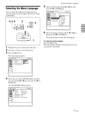
... m key, then press the , or ENTER key. The SET SETTING Menu appears. The menu display disappears automatically if no key is ENGLISH. 4, 5, 6 3 LAMP/ COVER TEMP/ FAN POWER SAVING ON/ STANDBY MENU PATTERN ENTER RESET LIGHT INPUT VIDEO MEMORY 2 1 1 Plug the AC power cord into the selected language . The menu display appears. PICTURE CTRL CONTRAST: 80 BRIGHT: 50 RGB ENHANCER: 30 COLOR TEMP: LOW INPUT-A Selecting the Menu Language 5 Select LANGUAGE with the M or m key, then...
... m key, then press the , or ENTER key. The SET SETTING Menu appears. The menu display disappears automatically if no key is ENGLISH. 4, 5, 6 3 LAMP/ COVER TEMP/ FAN POWER SAVING ON/ STANDBY MENU PATTERN ENTER RESET LIGHT INPUT VIDEO MEMORY 2 1 1 Plug the AC power cord into the selected language . The menu display appears. PICTURE CTRL CONTRAST: 80 BRIGHT: 50 RGB ENHANCER: 30 COLOR TEMP: LOW INPUT-A Selecting the Menu Language 5 Select LANGUAGE with the M or m key, then...
Operating Instructions
Page 18
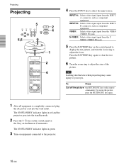
... connected, plug the AC power cord into the standby mode. 2 Press the I / 1 key on the control panel or the I key on the remote commander. Projecting Projecting 5 LAMP/ COVER TEMP/ FAN POWER SAVING ON/ STANDBY MENU PATTERN ENTER RESET 5,6 LIGHT INPUT VIDEO MEMORY 2 4 1 MUTING PIC INPUT SELECT VIDEO A B S VIDEO VIDEO MEMORY 1 2 3 4 5 6 OFF MENU RESET ENTER 2 4 4 Press the INPUT key to adjust the focus. INPUT-A: Selects video signal input from the VIDEO (VIDEO IN) jack. The ON/STANDBY indicator lights in green. 3 Turn on the control panel to display...
... connected, plug the AC power cord into the standby mode. 2 Press the I / 1 key on the control panel or the I key on the remote commander. Projecting Projecting 5 LAMP/ COVER TEMP/ FAN POWER SAVING ON/ STANDBY MENU PATTERN ENTER RESET 5,6 LIGHT INPUT VIDEO MEMORY 2 4 1 MUTING PIC INPUT SELECT VIDEO A B S VIDEO VIDEO MEMORY 1 2 3 4 5 6 OFF MENU RESET ENTER 2 4 4 Press the INPUT key to adjust the focus. INPUT-A: Selects video signal input from the VIDEO (VIDEO IN) jack. The ON/STANDBY indicator lights in green. 3 Turn on the control panel to display...
Operating Instructions
Page 20
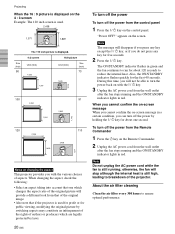
... on-screen message When you cannot confirm the on changing the aspect This projector provides you with the I / 1 key. About the air filter cleaning Clean the air filter every 300 hours to turn off the power by laws. 20 (GB) To turn off the power To turn off the power from the control panel 1 Press the I / 1 key on the Remote Commander. 2 Unplug the AC power cord from the wall outlet after the fan stops...
... on-screen message When you cannot confirm the on changing the aspect This projector provides you with the I / 1 key. About the air filter cleaning Clean the air filter every 300 hours to turn off the power by laws. 20 (GB) To turn off the power To turn off the power from the control panel 1 Press the I / 1 key on the Remote Commander. 2 Unplug the AC power cord from the wall outlet after the fan stops...
Operating Instructions
Page 23
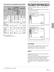
... input signal are not displayed in the menu. RGB - - - - The lower the setting, the smaller the horizontal size of the picture. PICTURE - - COLOR TEMP COLOR SYS DRC-MF - - - - - : Adjustable/can be set - : Not adjustable/can not be set The PICTURE CTRL Menu / The INPUT SETTING Menu The INPUT SETTING Menu The INPUT SETTING menu is input INPUT SETTING DOT PHASE: 50 SIZE H: 50 SHIFT H: 123 SCAN CONV: ON VIDEO MEMORY: OFF INPUT-A V: 123 800x600 Signal type DOT PHASE Adjusts the phase of a computer 23 (GB) Adjust the setting...
... input signal are not displayed in the menu. RGB - - - - The lower the setting, the smaller the horizontal size of the picture. PICTURE - - COLOR TEMP COLOR SYS DRC-MF - - - - - : Adjustable/can be set - : Not adjustable/can not be set The PICTURE CTRL Menu / The INPUT SETTING Menu The INPUT SETTING Menu The INPUT SETTING menu is input INPUT SETTING DOT PHASE: 50 SIZE H: 50 SHIFT H: 123 SCAN CONV: ON VIDEO MEMORY: OFF INPUT-A V: 123 800x600 Signal type DOT PHASE Adjusts the phase of a computer 23 (GB) Adjust the setting...
Operating Instructions
Page 25
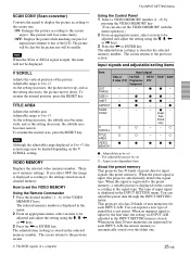
... narrow. RGB1) B&W - - - SCROLL setting. When the preset signal is input, this projector automatically detects the signal type. You can register a new type of signal that of the LCD. Using the Control Panel 1 Select a VIDEO MEMORY number (1 - 6) by pressing the VIDEO MEMORY key. (You can not be adjusted and adjust the setting using the M, m, < is not preset. The adjusted item (setting) is displayed on the V SCAN - Item DOT PHASE SIZE H Video or S video (Y/C) - SHIFT - - As the...
... narrow. RGB1) B&W - - - SCROLL setting. When the preset signal is input, this projector automatically detects the signal type. You can register a new type of signal that of the LCD. Using the Control Panel 1 Select a VIDEO MEMORY number (1 - 6) by pressing the VIDEO MEMORY key. (You can not be adjusted and adjust the setting using the M, m, < is not preset. The adjusted item (setting) is displayed on the V SCAN - Item DOT PHASE SIZE H Video or S video (Y/C) - SHIFT - - As the...
Operating Instructions
Page 27
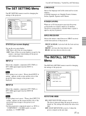
... SET SETTING Menu / The INSTALL SETTING Menu LANGUAGE Selects the language used for changing the settings of the projector. STATUS (on-screen display) Sets up the on . OFF: DIGIT KEYSTONE is reset to ON, the projector goes into the power saving mode if no signal is input for the menus, a message when turning off the power, and warning messages. Note If the setting is not correct, "Please check INPUT-B setting." FRONT & REAR: Activates both the front and rear detectors. The INSTALL SETTING Menu The INSTALL SETTING menu...
... SET SETTING Menu / The INSTALL SETTING Menu LANGUAGE Selects the language used for changing the settings of the projector. STATUS (on-screen display) Sets up the on . OFF: DIGIT KEYSTONE is reset to ON, the projector goes into the power saving mode if no signal is input for the menus, a message when turning off the power, and warning messages. Note If the setting is not correct, "Please check INPUT-B setting." FRONT & REAR: Activates both the front and rear detectors. The INSTALL SETTING Menu The INSTALL SETTING menu...

Operating Instructions
Page 34
... the lamp breaks, consult with qualified Sony personnel. • Pull out the lamp unit by loosening one after about 1000 hours for the OFF setting, or about 2000 hours for the ON setting in place. If you may scald your finger. When replacing the lamp after turning off the projector, then unplug the power cord. Note The lamp becomes a high temperature after using the projector Turn off the projector with...
... the lamp breaks, consult with qualified Sony personnel. • Pull out the lamp unit by loosening one after about 1000 hours for the OFF setting, or about 2000 hours for the ON setting in place. If you may scald your finger. When replacing the lamp after turning off the projector, then unplug the power cord. Note The lamp becomes a high temperature after using the projector Turn off the projector with...

Operating Instructions
Page 35
Maintenance 6 Close the lamp cover and tighten the screw. 7 Turn the projector back over. 8 Connect the power cord and turn the projector to the standby mode. 9 Press the following keys on the control panel in the following order for less than in five seconds each: RESET,
Maintenance 6 Close the lamp cover and tighten the screw. 7 Turn the projector back over. 8 Connect the power cord and turn the projector to the standby mode. 9 Press the following keys on the control panel in the following order for less than in five seconds each: RESET,
Operating Instructions
Page 36
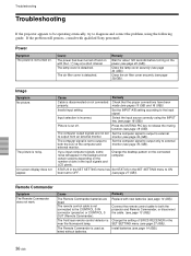
... 20 (GB)). Remote Commander Symptom The Remote Commander does not work. The lamp cover is not connected to the CONTROL S IN connector (projector) or CONTROL S OUT (Remote Commander). The remote control cable is detached. Change the setting of dots in the SET SETTING menu to ON been set to the input signal. Invalid input setting. The front/rear remote control detector is noisy. Troubleshooting Troubleshooting If the projector appears to be operating erratically, try to diagnose and correct the problem, using the INPUT key (see page...
... 20 (GB)). Remote Commander Symptom The Remote Commander does not work. The lamp cover is not connected to the CONTROL S IN connector (projector) or CONTROL S OUT (Remote Commander). The remote control cable is detached. Change the setting of dots in the SET SETTING menu to ON been set to the input signal. Invalid input setting. The front/rear remote control detector is noisy. Troubleshooting Troubleshooting If the projector appears to be operating erratically, try to diagnose and correct the problem, using the INPUT key (see page...
Operating Instructions
Page 37
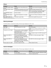
... messages Use the list below to check the meaning of the messages displayed on the screen. Both LAMP/COVER and The electric system failed. Warning messages Use the list below to check the meaning of the messages displayed on the power again (see page 27 (GB)). Set INPUT-A correctly (see page 20 (GB)). The TEMP/FAN indicator lights up. This input signal cannot be projected as the frequency is too high. The resolution setting of the output signal...
... messages Use the list below to check the meaning of the messages displayed on the screen. Both LAMP/COVER and The electric system failed. Warning messages Use the list below to check the meaning of the messages displayed on the power again (see page 27 (GB)). Set INPUT-A correctly (see page 20 (GB)). The TEMP/FAN indicator lights up. This input signal cannot be projected as the frequency is too high. The resolution setting of the output signal...

Operating Instructions
Page 39
...% Supplied accessories Remote Commander RM-PJVW10 (1) Size AA (R6) batteries (2) Lens Cap (1) AC power cord (1) Air filter (for replacement) (1) Operating Instructions (1) Design and specifications are subject to 240 V, 50/60 Hz Power consumption Max. 300 W (Standby mode: 6 W) Peak inrush current (1) Power ON, current probe method: 58.0A (240V) (2) Hot switching inrush current, measured in some areas. For details, please consult your nearest Sony office. 39 (GB) Other VD: Vertical sync input...
...% Supplied accessories Remote Commander RM-PJVW10 (1) Size AA (R6) batteries (2) Lens Cap (1) AC power cord (1) Air filter (for replacement) (1) Operating Instructions (1) Design and specifications are subject to 240 V, 50/60 Hz Power consumption Max. 300 W (Standby mode: 6 W) Peak inrush current (1) Power ON, current probe method: 58.0A (240V) (2) Hot switching inrush current, measured in some areas. For details, please consult your nearest Sony office. 39 (GB) Other VD: Vertical sync input...
Operating Instructions
Page 42
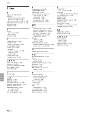
...) KEYSTONE MEM 27 (GB) Index L Lamp replacement 34 (GB) LAMP TIMER 28 (GB) LANGUAGE 27 (GB) Location and function of controls connector panel 12 (GB) control panel 11 (GB) front/left side 9 (GB) rear/right side/bottom 9 (GB) Remote Commander 13 (GB) M, N Menu clearing the menu display 17 (GB) INPUT SETTING menu 23 (GB) INSTALL SETTING menu 27 (GB) PICTURE CTRL menu 22 (GB) SET SETTING menu 27 (GB) using the menu 21 (GB) Messages cautions 37 (GB) warnings 37...
...) KEYSTONE MEM 27 (GB) Index L Lamp replacement 34 (GB) LAMP TIMER 28 (GB) LANGUAGE 27 (GB) Location and function of controls connector panel 12 (GB) control panel 11 (GB) front/left side 9 (GB) rear/right side/bottom 9 (GB) Remote Commander 13 (GB) M, N Menu clearing the menu display 17 (GB) INPUT SETTING menu 23 (GB) INSTALL SETTING menu 27 (GB) PICTURE CTRL menu 22 (GB) SET SETTING menu 27 (GB) using the menu 21 (GB) Messages cautions 37 (GB) warnings 37...


