Operating Instructions
Page 13
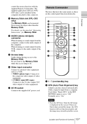
...image may extend beyond the screen. 13 Location and Function of the computer. Do not remove the Memory Stick while the access lamp is displayed on the control panel function identically. For details, see the attached "Operating Instructions" for Memory Stick. 4 AUDIO ... INPUT APA qa MENU PIC ENTER 0 MUTING 9 8 + RESET R - Used when "Smart APA" in the computer attached to "Off." The supplied application software (VPLCX5 only) can be inserted. Normally set to this connector. 3 Memory Stick slot (VPL-CX5 only) The Memory Stick can be installed in the SET SETTING...
...image may extend beyond the screen. 13 Location and Function of the computer. Do not remove the Memory Stick while the access lamp is displayed on the control panel function identically. For details, see the attached "Operating Instructions" for Memory Stick. 4 AUDIO ... INPUT APA qa MENU PIC ENTER 0 MUTING 9 8 + RESET R - Used when "Smart APA" in the computer attached to "Off." The supplied application software (VPLCX5 only) can be inserted. Normally set to this connector. 3 Memory Stick slot (VPL-CX5 only) The Memory Stick can be installed in the SET SETTING...
Operating Instructions
Page 37
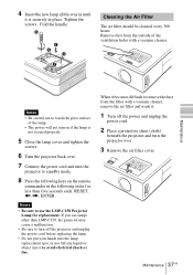
... not secured properly. 5 Close the lamp cover and tighten the screws. 6 Turn the projector back over. 7 Connect the power cord and turn on if the lamp is securely in the following order for less than five seconds each: RESET, Remove dust from the outside of the lamp. • The power will not ...turn the projector to touch the glass surface of the ventilation holes with a vacuum cleaner....
... not secured properly. 5 Close the lamp cover and tighten the screws. 6 Turn the projector back over. 7 Connect the power cord and turn on if the lamp is securely in the following order for less than five seconds each: RESET, Remove dust from the outside of the lamp. • The power will not ...turn the projector to touch the glass surface of the ventilation holes with a vacuum cleaner....
Operating Instructions
Page 48
... 44 Input-A Signal Sel. .........33 Installation examples .....16 notes 7 unsuitable conditions .... 7 unsuitable installation .. 7 L Lamp Mode 34 Lamp replacement .......... 36 Lamp Timer 35 Language 33 selecting the menu language 21 Location and function of controls connector panel .......... 12 control panel 12 rear... ...... 11 Precautions 6 R Remote Commander ...... 13 location and function of controls 13 Remote control detector front 11 Reset resettable items 29 resetting the item ........ 29 RGB Enhancer 30 S Scan Converter 31 Screen size 16, 43 SET SETTING menu ..... 32...
... 44 Input-A Signal Sel. .........33 Installation examples .....16 notes 7 unsuitable conditions .... 7 unsuitable installation .. 7 L Lamp Mode 34 Lamp replacement .......... 36 Lamp Timer 35 Language 33 selecting the menu language 21 Location and function of controls connector panel .......... 12 control panel 12 rear... ...... 11 Precautions 6 R Remote Commander ...... 13 location and function of controls 13 Remote control detector front 11 Reset resettable items 29 resetting the item ........ 29 RGB Enhancer 30 S Scan Converter 31 Screen size 16, 43 SET SETTING menu ..... 32...


