Operating Instructions (primary manual)
Page 2
..., Mail Drop #T1-11, Park Ridge, NJ 07656 Declaration of Conformity Trade Name: Model No.: Responsible Party: Address: Telephone No.: SONY SDM-P82 Sony Electronics Inc. 680 Kinderkamack Road,Oradell,NJ 07649 USA 201-930-6972 This device complies with the instructions, may call upon your authority to Part...shipped to USA/Canada, install only a UL LISTED/CSA LABELLED power supply cord meeting the following two conditions: (1) This device may cause undesired operation. This monitor complies with the limits for USA/Canada only. Record these numbers in a particular installation.
..., Mail Drop #T1-11, Park Ridge, NJ 07656 Declaration of Conformity Trade Name: Model No.: Responsible Party: Address: Telephone No.: SONY SDM-P82 Sony Electronics Inc. 680 Kinderkamack Road,Oradell,NJ 07649 USA 201-930-6972 This device complies with the instructions, may call upon your authority to Part...shipped to USA/Canada, install only a UL LISTED/CSA LABELLED power supply cord meeting the following two conditions: (1) This device may cause undesired operation. This monitor complies with the limits for USA/Canada only. Record these numbers in a particular installation.
Operating Instructions (primary manual)
Page 3
... (analog RGB 7 Setup 3: Connect the power cord 8 Setup 4: Bundle the cords and cables 9 Setup 5: Turn on the monitor and computer 9 Setup 6: Adjusting the tilt 10 Selecting the input signal (INPUT button 11 Customizing Your Monitor 11 Navigating the menu 11 BACKLIGHT 12 US CONTRAST 12 BRIGHTNESS 12 SCREEN (analog RGB signal only...
... (analog RGB 7 Setup 3: Connect the power cord 8 Setup 4: Bundle the cords and cables 9 Setup 5: Turn on the monitor and computer 9 Setup 6: Adjusting the tilt 10 Selecting the input signal (INPUT button 11 Customizing Your Monitor 11 Navigating the menu 11 BACKLIGHT 12 US CONTRAST 12 BRIGHTNESS 12 SCREEN (analog RGB signal only...
Operating Instructions (primary manual)
Page 4
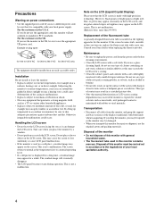
...and packing materials. Example of the fluorescent tube A specially designed fluorescent tube is displayed for a long time, a residual image may be injured or the monitor may appear for repair or shipment, use a different power cord, be carried out in direct sunlight. The screen returns to normal as the temperature rises... If the screen becomes dark, unstable, or does not turn on the LCD screen. If setting up temporarily in the U.S.A. This type of your Sony dealer when replacing the fluorescent tube. If you do not use the appropriate UK power cord.
...and packing materials. Example of the fluorescent tube A specially designed fluorescent tube is displayed for a long time, a residual image may be injured or the monitor may appear for repair or shipment, use a different power cord, be carried out in direct sunlight. The screen returns to normal as the temperature rises... If the screen becomes dark, unstable, or does not turn on the LCD screen. If setting up temporarily in the U.S.A. This type of your Sony dealer when replacing the fluorescent tube. If you do not use the appropriate UK power cord.

Operating Instructions (primary manual)
Page 5
... the corresponding indicator, (INPUT1 or INPUT2) lights up , press the MAIN POWER switch (8). H MAIN POWER switch (page 9) This switch turns the monitor's main power on and off. Identifying parts and controls See the pages in red. B MENU button (page 11) This button turns the menu screen... 9 A 1 (Power) switch and 1 (Power) indicator (pages 9, 17, 21) This switch turns the monitor on when the 1 (power) indicator lights up in parentheses for the current input signal. To turn the monitor off . C M/m buttons (page 11) These buttons are used to select the menu items and make adjustments....
... the corresponding indicator, (INPUT1 or INPUT2) lights up , press the MAIN POWER switch (8). H MAIN POWER switch (page 9) This switch turns the monitor's main power on and off. Identifying parts and controls See the pages in red. B MENU button (page 11) This button turns the menu screen... 9 A 1 (Power) switch and 1 (Power) indicator (pages 9, 17, 21) This switch turns the monitor on when the 1 (power) indicator lights up in parentheses for the current input signal. To turn the monitor off . C M/m buttons (page 11) These buttons are used to select the menu items and make adjustments....

Operating Instructions (primary manual)
Page 6
... connecting cords and cables. N AC IN connector (page 8) Connect the power cord (supplied). qa qs qd qf J Back cover (page 7) Remove this cover to the monitor. qg qh 6 O Arm cover (page 9) Remove this cover when you connect cables or cords. L HD15 input connector (analog RGB) for INPUT1 (page 7) This connector inputs...
... connecting cords and cables. N AC IN connector (page 8) Connect the power cord (supplied). qa qs qd qf J Back cover (page 7) Remove this cover to the monitor. qg qh 6 O Arm cover (page 9) Remove this cover when you connect cables or cords. L HD15 input connector (analog RGB) for INPUT1 (page 7) This connector inputs...
Operating Instructions (primary manual)
Page 7
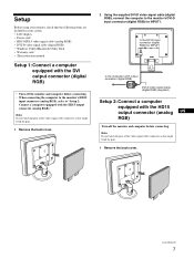
... manual Setup 1: Connect a computer equipped with the DVI output connector (digital RGB) • Turn off the monitor and computer before connecting. • When connecting the computer to the monitor's HD15 input connector (analog RGB), refer to the computer's DVI output connector (digital RGB) DVI-D video signal...the pins. 1 Remove the back cover. 2 Using the supplied DVI-D video signal cable (digital RGB), connect the computer to the monitor's DVI-D input connector (digital RGB) for INPUT1 to "Setup 2: Connect a computer equipped with the HD15 output connector (analog US RGB) Turn ...
... manual Setup 1: Connect a computer equipped with the DVI output connector (digital RGB) • Turn off the monitor and computer before connecting. • When connecting the computer to the monitor's HD15 input connector (analog RGB), refer to the computer's DVI output connector (digital RGB) DVI-D video signal...the pins. 1 Remove the back cover. 2 Using the supplied DVI-D video signal cable (digital RGB), connect the computer to the monitor's DVI-D input connector (digital RGB) for INPUT1 to "Setup 2: Connect a computer equipped with the HD15 output connector (analog US RGB) Turn ...

Operating Instructions (primary manual)
Page 8
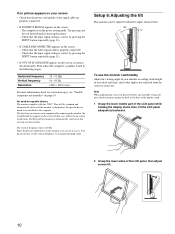
... cable. 8 Connect the adapter to the following illustrations. 2 Using the supplied HD15-HD15 video signal cable (analog RGB), connect the computer to the monitor's HD 15 input connector (analog RGB) for INPUT1 or INPUT2 to power outlet power cord (supplied) 2 HD15-HD15 video signal to the computer's ...supplied) if necessary. x Connecting to an IBM PC/AT or compatible computer Setup 3: Connect the power cord 1 Connect the supplied power cord to the monitor's AC IN connector. 2 Connect it to the HD 15 input connector (analog RGB) for INPUT 1 or INPUT2. to the HD 15 input connector ...
... cable. 8 Connect the adapter to the following illustrations. 2 Using the supplied HD15-HD15 video signal cable (analog RGB), connect the computer to the monitor's HD 15 input connector (analog RGB) for INPUT1 or INPUT2 to power outlet power cord (supplied) 2 HD15-HD15 video signal to the computer's ...supplied) if necessary. x Connecting to an IBM PC/AT or compatible computer Setup 3: Connect the power cord 1 Connect the supplied power cord to the monitor's AC IN connector. 2 Connect it to the HD 15 input connector (analog RGB) for INPUT 1 or INPUT2. to the HD 15 input connector ...

Operating Instructions (primary manual)
Page 9
.... 4 Replace the arm cover and back cover. 1 arm cover 2 4 back cover Setup 5: Turn on the monitor and computer 1 Press the MAIN POWER switch on the left side of the monitor in the direction of the cords and cables inside the stand, leave them hanging down outside the stand. 3 Turn... on the computer. 4 Press the INPUT button repeatedly and select the desired input signal. The installation of the monitor. The selected input signal indicator lights up in green. For more information, see "Selecting the input signal (INPUT button)" on the front right of...
.... 4 Replace the arm cover and back cover. 1 arm cover 2 4 back cover Setup 5: Turn on the monitor and computer 1 Press the MAIN POWER switch on the left side of the monitor in the direction of the cords and cables inside the stand, leave them hanging down outside the stand. 3 Turn... on the computer. 4 Press the INPUT button repeatedly and select the desired input signal. The installation of the monitor. The selected input signal indicator lights up in green. For more information, see "Selecting the input signal (INPUT button)" on the front right of...
Operating Instructions (primary manual)
Page 10
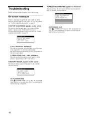
... • Check that the video signal cable is properly connected. - Check that the power cord and the video signal cable are unobtrusive on the monitor, you turn on your desk and chair, and so that the input signal setting is correct by pressing the INPUT button repeatedly (page 11). &#...8226; If CABLE DISCONNECTED appears on the screen: - The vertical frequency turns to hit the monitor against the desk or the base of the display stand. 1 Grasp the lower middle part of the LCD panel while holding the display stand, then...
... • Check that the video signal cable is properly connected. - Check that the power cord and the video signal cable are unobtrusive on the monitor, you turn on your desk and chair, and so that the input signal setting is correct by pressing the INPUT button repeatedly (page 11). &#...8226; If CABLE DISCONNECTED appears on the screen: - The vertical frequency turns to hit the monitor against the desk or the base of the display stand. 1 Grasp the lower middle part of the LCD panel while holding the display stand, then...

Operating Instructions (primary manual)
Page 11
... connector (analog RGB) for INPUT1 HD15 input connector (analog RGB) for INPUT2 Customizing Your Monitor Before making adjustments for at least 30 minutes before making adjustments Connect the monitor and the computer, and turn them on your monitor using the on-screen menu. Press the M/m buttons to make numerous adjustments to your screen...
... connector (analog RGB) for INPUT1 HD15 input connector (analog RGB) for INPUT2 Customizing Your Monitor Before making adjustments for at least 30 minutes before making adjustments Connect the monitor and the computer, and turn them on your monitor using the on-screen menu. Press the M/m buttons to make numerous adjustments to your screen...
Operating Instructions (primary manual)
Page 12
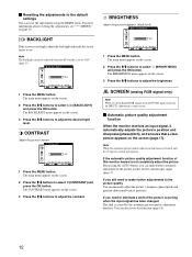
... MENU button. The BRIGHTNESS menu appears on the screen. 2 Press the M/m buttons to adjust the brightness. You can deactivate this monitor seems to the default settings You can reset the adjustments using the RESET menu. CONTRAST Adjust the picture contrast. SCREEN (analog RGB signal...screen. 2 Press the M/m buttons to select 8 (BRIGHTNESS) and press the OK button. x Automatic picture quality adjustment function When the monitor receives an input signal, it automatically adjusts the picture's position and sharpness (phase/pitch), and ensures that a clear picture appears on ...
... MENU button. The BRIGHTNESS menu appears on the screen. 2 Press the M/m buttons to adjust the brightness. You can deactivate this monitor seems to the default settings You can reset the adjustments using the RESET menu. CONTRAST Adjust the picture contrast. SCREEN (analog RGB signal...screen. 2 Press the M/m buttons to select 8 (BRIGHTNESS) and press the OK button. x Automatic picture quality adjustment function When the monitor receives an input signal, it automatically adjusts the picture's position and sharpness (phase/pitch), and ensures that a clear picture appears on ...
Operating Instructions (primary manual)
Page 13
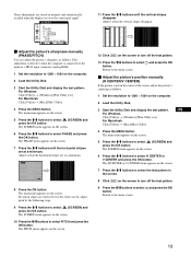
... Windows Click [Utility] t [Windows]/[Win Utility.exe]. and press the OK x Adjust the picture's position manually (H CENTER/V CENTER) If the picture is connected to the monitor's HD15 input connector (analog RGB). 1 Set the resolution to 1280 × 1024 on the screen. 6 Press the M/m buttons to select PITCH and press the OK...
... Windows Click [Utility] t [Windows]/[Win Utility.exe]. and press the OK x Adjust the picture's position manually (H CENTER/V CENTER) If the picture is connected to the monitor's HD15 input connector (analog RGB). 1 Set the resolution to 1280 × 1024 on the screen. 6 Press the M/m buttons to select PITCH and press the OK...

Operating Instructions (primary manual)
Page 15
ZOOM The monitor is set the (ZOOM) menu to select the desired mode. • FULL2 (The default setting): The input signal is displayed on the screen in full. ...
ZOOM The monitor is set the (ZOOM) menu to select the desired mode. • FULL2 (The default setting): The input signal is displayed on the screen in full. ...

Operating Instructions (primary manual)
Page 17
...reduced. Reducing the power consumption (ECO mode) If you can manually set these adjustments (page 12). The factory preset mode When the monitor receives an input signal, it automatically adjusts the picture's position and sharpness (phase/pitch), and ensures that a clear picture appears on ..., and pictures position manually For some input signals, the automatic picture quality adjustment function of the factory preset modes, the monitor may not completely adjust the picture position, phase, and pitch. This adjustment data is automatically stored in memory so that do...
...reduced. Reducing the power consumption (ECO mode) If you can manually set these adjustments (page 12). The factory preset mode When the monitor receives an input signal, it automatically adjusts the picture's position and sharpness (phase/pitch), and ensures that a clear picture appears on ..., and pictures position manually For some input signals, the automatic picture quality adjustment function of the factory preset modes, the monitor may not completely adjust the picture position, phase, and pitch. This adjustment data is automatically stored in memory so that do...
Operating Instructions (primary manual)
Page 18
...If NO INPUT SIGNAL appears on the screen This indicates that no signal is not supported by the monitor's specifications. D x x x . D GO TO POWER SAVE GO TO POWER SAVE If the ZZ... (POWER SAVE) is set ... enter the power saving mode after about 5 seconds from the time the message is not supported by the monitor's specifications (1280 × 1024 or less). If OUT OF SCAN RANGE appears on the screen This indicates... has been disconnected from the time the message is not supported by the monitor's specifications. D GO TO POWER SAVE GO TO POWER SAVE If the ZZ... (POWER SAVE) is set ...
...If NO INPUT SIGNAL appears on the screen This indicates that no signal is not supported by the monitor's specifications. D x x x . D GO TO POWER SAVE GO TO POWER SAVE If the ZZ... (POWER SAVE) is set ... enter the power saving mode after about 5 seconds from the time the message is not supported by the monitor's specifications (1280 × 1024 or less). If OUT OF SCAN RANGE appears on the screen This indicates... has been disconnected from the time the message is not supported by the monitor's specifications. D GO TO POWER SAVE GO TO POWER SAVE If the ZZ... (POWER SAVE) is set ...
Operating Instructions (primary manual)
Page 19
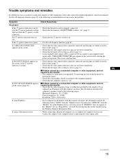
... not a malfunction. If OUT OF SCAN RANGE appears on the screen, • Check that specified for this monitor, reconnect the old monitor and do not resolve the problem. Select "SONY" from the "Manufacturers" list and select "SDM-P82" from the "Models" list in . • Check that the input select setting is within that the video...
... not a malfunction. If OUT OF SCAN RANGE appears on the screen, • Check that specified for this monitor, reconnect the old monitor and do not resolve the problem. Select "SONY" from the "Manufacturers" list and select "SDM-P82" from the "Models" list in . • Check that the input select setting is within that the video...
Operating Instructions (primary manual)
Page 20
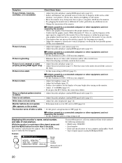
... Sony dealer and give the following information: • Model name: SDM-P82 • Serial number • Name and specifications of your graphics board manual for more than 5 seconds. White does not look white. • Adjust the color temperature (page 14). Displaying this monitor.... Symptom Check these items Picture flickers, bounces, oscillates, or is too small. • Set the zoom setting to FULL2 (page 15). Picture is fuzzy. Example MENU INFORMATION MODEL : SDM-P82 SER. Picture is not centered or sized...
... Sony dealer and give the following information: • Model name: SDM-P82 • Serial number • Name and specifications of your graphics board manual for more than 5 seconds. White does not look white. • Adjust the color temperature (page 14). Displaying this monitor.... Symptom Check these items Picture flickers, bounces, oscillates, or is too small. • Set the zoom setting to FULL2 (page 15). Picture is fuzzy. Example MENU INFORMATION MODEL : SDM-P82 SER. Picture is not centered or sized...

Operating Instructions (primary manual)
Page 21
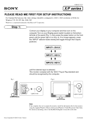
...a self-diagnosis function. If all four color bars appear (white, red, green, blue), the monitor is a potential monitor failure. Reconnect the video input cables and check the condition of your authorized Sony dealer of total horizontal time or 0.8 µs, whichever is larger. • Horizontal blanking width should...and the 1 (power) indicator is green 1 Turn off the 1 (power) switch and disconnect the video signal cables from the monitor. 2 Turn the monitor on the keyboard or moving the mouse. Specifications LCD panel Panel type: a-Si TFT Active Matrix Picture size: 18.1 inch Input ...
...a self-diagnosis function. If all four color bars appear (white, red, green, blue), the monitor is a potential monitor failure. Reconnect the video input cables and check the condition of your authorized Sony dealer of total horizontal time or 0.8 µs, whichever is larger. • Horizontal blanking width should...and the 1 (power) indicator is green 1 Turn off the 1 (power) switch and disconnect the video signal cables from the monitor. 2 Turn the monitor on the keyboard or moving the mouse. Specifications LCD panel Panel type: a-Si TFT Active Matrix Picture size: 18.1 inch Input ...
Read Me First for Setup Instructions
Page 1
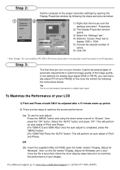
... the 3 inputs positions: INPUT1: DVI-D mM INPUT1: HD15 mM INPUT2: HD15 until the green light is selected. Sony Corporation © 2002 Printed in green Note If the computer does not recognize the monitor, install the information file for Windows® 95, 98, NT, Me, 2000, XP. Fig. 1 Fig.... front panel until the desired input is on installing, refer to 1280 × 1024 resolution at 60 Hz for this monitor using the supplied Windows Monitor Information/Windows Utility/Macintosh Utility Disk. Step 1: Connect your display to your Display power switch located on the disk. This...
... the 3 inputs positions: INPUT1: DVI-D mM INPUT1: HD15 mM INPUT2: HD15 until the green light is selected. Sony Corporation © 2002 Printed in green Note If the computer does not recognize the monitor, install the information file for Windows® 95, 98, NT, Me, 2000, XP. Fig. 1 Fig.... front panel until the desired input is on installing, refer to 1280 × 1024 resolution at 60 Hz for this monitor using the supplied Windows Monitor Information/Windows Utility/Macintosh Utility Disk. Step 1: Connect your display to your Display power switch located on the disk. This...
Read Me First for Setup Instructions
Page 2
... input signal (VGA or HD15), you turn on your monitor, it performs several types of automatic adjustments to maximize the performance of Pitch and Phase. (For SDM-X72 and SDM-X82) Once the auto adjust is not available in NT...the auto adjust: Press the "MENU" button and using the down arrow to scroll to www.sony.com/displays/support or call 866-357-7669 (SONY) This will perform an auto adjust of your display. For additional support, go to "Screen",... colors. 6) Click OK. 6 * If the "Settings" tub is completed, press the "MENU" button. (For SDM-P82) Press the "AUTO" button.
... input signal (VGA or HD15), you turn on your monitor, it performs several types of automatic adjustments to maximize the performance of Pitch and Phase. (For SDM-X72 and SDM-X82) Once the auto adjust is not available in NT...the auto adjust: Press the "MENU" button and using the down arrow to scroll to www.sony.com/displays/support or call 866-357-7669 (SONY) This will perform an auto adjust of your display. For additional support, go to "Screen",... colors. 6) Click OK. 6 * If the "Settings" tub is completed, press the "MENU" button. (For SDM-P82) Press the "AUTO" button.


