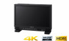
Operating Instructions
Page 2
... of Parts and Controls ..... 7 Front Panel 7 Input Signals and Adjustable/Setting Items 11 Quad View Functions and Adjustable/ Setting Items 12 Rear Panel 13 Connecting the SDI Signals 14 Handling a USB memory stick 15 Notes on USB memory sticks 15 Removing the Stand (Included as Standard) ... 16 Attaching the Handle (For PVM-X1800 only) ... 16 Connecting the AC Power Cord 17 Selecting a Channel 17 Managing the Setting Values 18 About the Menu Screen 18 Using the Menu...
... of Parts and Controls ..... 7 Front Panel 7 Input Signals and Adjustable/Setting Items 11 Quad View Functions and Adjustable/ Setting Items 12 Rear Panel 13 Connecting the SDI Signals 14 Handling a USB memory stick 15 Notes on USB memory sticks 15 Removing the Stand (Included as Standard) ... 16 Attaching the Handle (For PVM-X1800 only) ... 16 Connecting the AC Power Cord 17 Selecting a Channel 17 Managing the Setting Values 18 About the Menu Screen 18 Using the Menu...
Operating Instructions
Page 3
... power cord from the wall outlet if it can damage the screen. Depending on (red, green, or blue), or flashing. Thus a very small proportion of pixels may be easily accessible. This may cause a malfunction to the surface of the unit becomes extremely hot. Doing so may overload the contact point of a plug. When using headphones, do not bring the headphone cable...
... power cord from the wall outlet if it can damage the screen. Depending on (red, green, or blue), or flashing. Thus a very small proportion of pixels may be easily accessible. This may cause a malfunction to the surface of the unit becomes extremely hot. Doing so may overload the contact point of a plug. When using headphones, do not bring the headphone cable...
Operating Instructions
Page 4
... environments may cause image smearing or/and flicker on the screen continuously, or repeatedly over extended periods. In this manual, this occurs, display a white screen display or a video on the HDR (High Dynamic Range) display, see "On High Brightness Display" (page 4). To reduce the risk of the connected equipment, operate the connected equipment accordingly. Also, consider removing the frame during the Multi-View display, or displaying the signal level of...
... environments may cause image smearing or/and flicker on the screen continuously, or repeatedly over extended periods. In this manual, this occurs, display a white screen display or a video on the HDR (High Dynamic Range) display, see "On High Brightness Display" (page 4). To reduce the risk of the connected equipment, operate the connected equipment accordingly. Also, consider removing the frame during the Multi-View display, or displaying the signal level of...

Operating Instructions
Page 5
... supplied cleaning cloth or a soft dry cloth to remove dirt. Stubborn stains may damage the screen. Use a blower to an external network, as security issues may form on its own. 5 Doing so may damage the unit. On Fan Error The unit has a built in red, turn off the power and contact an authorized Sony dealer. Do not connect to remove...
... supplied cleaning cloth or a soft dry cloth to remove dirt. Stubborn stains may damage the screen. Use a blower to an external network, as security issues may form on its own. 5 Doing so may damage the unit. On Fan Error The unit has a built in red, turn off the power and contact an authorized Sony dealer. Do not connect to remove...

Operating Instructions
Page 7
...: F1 button: Ch.1 F2 button: Ch.2 F3 button: Ch.3 F4 button: Ch.4 F5 button: Mono F6 button: Quad View F7 button: Blue Only F8 button: Internal Signal F9 button: Int. For details, refer to the (headphones) jack. (USB) connector Used for battery charge and/or other purposes other channels. Signal Pattern F10 button: Marker F11 button: Time Code 7 Audio is output. The factory default settings are connected to "User LUT" (page 23) and "Update...
...: F1 button: Ch.1 F2 button: Ch.2 F3 button: Ch.3 F4 button: Ch.4 F5 button: Mono F6 button: Quad View F7 button: Blue Only F8 button: Internal Signal F9 button: Int. For details, refer to the (headphones) jack. (USB) connector Used for battery charge and/or other purposes other channels. Signal Pattern F10 button: Marker F11 button: Time Code 7 Audio is output. The factory default settings are connected to "User LUT" (page 23) and "Update...

Operating Instructions
Page 8
... Setting" menu. "Chr./Bright./ Cont." BACK button When the menu is displayed, press the button to reset the value of the F9 to F12 buttons to turn the control to select a menu item or setting value, and then press the control to "User Color Temp." (page 23). ADJUST knob Adjust the selected color under "Ch. Lights up in red during sleep mode and lights up in green Note If a no input-signal state continues for adjustment. Flashes in green Lights...
... Setting" menu. "Chr./Bright./ Cont." BACK button When the menu is displayed, press the button to reset the value of the F9 to F12 buttons to turn the control to select a menu item or setting value, and then press the control to "User Color Temp." (page 23). ADJUST knob Adjust the selected color under "Ch. Lights up in red during sleep mode and lights up in green Note If a no input-signal state continues for adjustment. Flashes in green Lights...

Operating Instructions
Page 9
... the panel from overheating 1) When using the controller buttons. Menu operation buttons Button MENU button ENTER button Operations When the on-screen menu is displayed, press the button to the previous value. Power button Button MONITOR switch Operations Switches the unit status. Rotary encoder/MANUAL buttons Knob CONTRAST knob BRIGHT knob CHROMA knob PHASE knob Operations Adjusts the picture brightness under "User Color Temp." (page 23) in the "User Preset Setting" menu. Adjusts the picture brightness under "User Color Temp." (page 23) in the "User Preset Setting" menu. Setting...
... the panel from overheating 1) When using the controller buttons. Menu operation buttons Button MENU button ENTER button Operations When the on-screen menu is displayed, press the button to the previous value. Power button Button MONITOR switch Operations Switches the unit status. Rotary encoder/MANUAL buttons Knob CONTRAST knob BRIGHT knob CHROMA knob PHASE knob Operations Adjusts the picture brightness under "User Color Temp." (page 23) in the "User Preset Setting" menu. Adjusts the picture brightness under "User Color Temp." (page 23) in the "User Preset Setting" menu. Setting...
Operating Instructions
Page 11
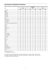
Input Signals and Adjustable/Setting Items Item CHROMA BRIGHT CONTRAST APERTURE RGB Range YCC Range EOTF Color Space Transfer Matrix Color Temp. User Color Temp. (manual adjsutment) User LUT Marker Volume Audio Muting WFM 1) Vector 1) ALM 1) Internal Signal Int. Dr. Tally 3) : Adjustable/can be set × : Not adjustable/cannot be set 4K SDI YCbCr RGB × × ×...
Input Signals and Adjustable/Setting Items Item CHROMA BRIGHT CONTRAST APERTURE RGB Range YCC Range EOTF Color Space Transfer Matrix Color Temp. User Color Temp. (manual adjsutment) User LUT Marker Volume Audio Muting WFM 1) Vector 1) ALM 1) Internal Signal Int. Dr. Tally 3) : Adjustable/can be set × : Not adjustable/cannot be set 4K SDI YCbCr RGB × × ×...
Operating Instructions
Page 12
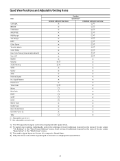
User Color Temp. (manual adjsutment) User LUT Marker Volume Audio Muting WFM Vector ALM Internal Signal Int. Signal Pattern Pixel Zoom Time Code Mono Blue Only R Off G Off B Off Native Scan Under Scan Black Detail Mode Dynamic Cont. Dr. Tally : Adjustable/can be set × : Not adjustable/cannot be displayed with Quad View. 2) To switch each setting individually, select the settings of choice under "Ch. Setting" in the "User Preset Setting" menu, then set Common setting for four...
User Color Temp. (manual adjsutment) User LUT Marker Volume Audio Muting WFM Vector ALM Internal Signal Int. Signal Pattern Pixel Zoom Time Code Mono Blue Only R Off G Off B Off Native Scan Under Scan Black Detail Mode Dynamic Cont. Dr. Tally : Adjustable/can be set × : Not adjustable/cannot be displayed with Quad View. 2) To switch each setting individually, select the settings of choice under "Ch. Setting" in the "User Preset Setting" menu, then set Common setting for four...
Operating Instructions
Page 13
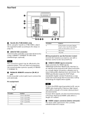
.... Tally Green Tally Red Wiring required to use the Remote Control Connect the function you to enjoy high quality digital picture and sound. "Ch.4" is specified. HDMI (High-Definition Multimedia Interface) is output. 13 Note To input the HDMI signal equivalent to 4K, use with a Remote Control to the Ground (Pin 5). HDMI IN (HDMI input) connector Input connector for digital video signals. GND Pin number 6 7 8 Functions All the markers set in the "User Preset Setting" menu are all turned on...
.... Tally Green Tally Red Wiring required to use the Remote Control Connect the function you to enjoy high quality digital picture and sound. "Ch.4" is specified. HDMI (High-Definition Multimedia Interface) is output. 13 Note To input the HDMI signal equivalent to 4K, use with a Remote Control to the Ground (Pin 5). HDMI IN (HDMI input) connector Input connector for digital video signals. GND Pin number 6 7 8 Functions All the markers set in the "User Preset Setting" menu are all turned on...

Operating Instructions
Page 14
... Connect the supplied AC power cord. Main power switch Press to the SDI IN connectors of "System Setting" in the "System" menu. or an equivalent) is output from the SDI OUT connector, a 12G-SDI cable (L-5.5CUHD manufactured by the auto power-off or in sleep mode. If a 12G-SDI or 6G-SDI signal is recommended. SDI IN (SDI input) connectors (BNC) Input connectors for serial digital signals. Connecting the SDI Signals...
... Connect the supplied AC power cord. Main power switch Press to the SDI IN connectors of "System Setting" in the "System" menu. or an equivalent) is output from the SDI OUT connector, a 12G-SDI cable (L-5.5CUHD manufactured by the auto power-off or in sleep mode. If a 12G-SDI or 6G-SDI signal is recommended. SDI IN (SDI input) connectors (BNC) Input connectors for serial digital signals. Connecting the SDI Signals...
Operating Instructions
Page 17
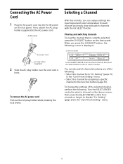
... a specific channel to display "Ch. Connecting the AC Power Cord 1 Plug the AC power cord into the AC IN socket on the front panel. Then, attach the AC plug holder (supplied) to switch channels. To remove the AC power cord Pull out the AC plug holder while pressing the lock levers. Setting" (page 21) in the "User Preset Setting" menu. 17 Turn the SELECT/ENTER control to select a channel on the above screen, then...
... a specific channel to display "Ch. Connecting the AC Power Cord 1 Plug the AC power cord into the AC IN socket on the front panel. Then, attach the AC plug holder (supplied) to switch channels. To remove the AC power cord Pull out the AC plug holder while pressing the lock levers. Setting" (page 21) in the "User Preset Setting" menu. 17 Turn the SELECT/ENTER control to select a channel on the above screen, then...
Operating Instructions
Page 18
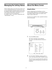
... orange. 2 Turn the SELECT/ENTER control to select a menu, then press the SELECT/ENTER control. When you load all the backup setting values collectively, you are made on the front panel. 1 Press the MENU button. For details, refer to enter the password. The menu selecting screen appears. Use the menu with a password. Using the Menu Various adjustments and settings, such as picture quality adjustment, input signals setting, and default setting change, are not required to "User Data...
... orange. 2 Turn the SELECT/ENTER control to select a menu, then press the SELECT/ENTER control. When you load all the backup setting values collectively, you are made on the front panel. 1 Press the MENU button. For details, refer to enter the password. The menu selecting screen appears. Use the menu with a password. Using the Menu Various adjustments and settings, such as picture quality adjustment, input signals setting, and default setting change, are not required to "User Data...
Operating Instructions
Page 23
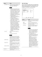
... select a marker preset between "Preset1" and "Preset10." Adjusts the color balance (bias) of R (red)/G (green)/B (blue). Select the marker preset to be adjusted. Select the audio preset to be used for the selected channel. Copy another channel's data to the monitor" (page 24). Submenu User Color Temp. Check the black level with the signal level by changing the backlight brightness. For details, see "Loading 3D LUT files...
... select a marker preset between "Preset1" and "Preset10." Adjusts the color balance (bias) of R (red)/G (green)/B (blue). Select the marker preset to be adjusted. Select the audio preset to be used for the selected channel. Copy another channel's data to the monitor" (page 24). Submenu User Color Temp. Check the black level with the signal level by changing the backlight brightness. For details, see "Loading 3D LUT files...

Operating Instructions
Page 27
... a position from 1 to 4096. Height: Sets the height of the area marker 1/2. You cannot select when HDMI is input as "CH1" is selected in "Left Audio," you cannot select a channel other than a channel from channels "CH1" to be configured. Adjusts the volume of the image display area as "CH2" is selected in "Right Audio." You cannot select when HDMI is input as the starting...
... a position from 1 to 4096. Height: Sets the height of the area marker 1/2. You cannot select when HDMI is input as "CH1" is selected in "Left Audio," you cannot select a channel other than a channel from channels "CH1" to be configured. Adjusts the volume of the image display area as "CH2" is selected in "Right Audio." You cannot select when HDMI is input as the starting...

Operating Instructions
Page 30
... Over Range. Sets the background of the WFM (Wave Form Monitor), Vector (vector scope), and audio level meter screens. Black: The background turns black. Select 20% to enlarge a 0 to 20% area of the signal level and 30% to enlarge a 0 to 1280 × 720 are input. Submenu Position WFM/VS ALM Transparency Intensity WFM/VS Setting Note WFM, Vector, and ALM are displayed...
... Over Range. Sets the background of the WFM (Wave Form Monitor), Vector (vector scope), and audio level meter screens. Black: The background turns black. Select 20% to enlarge a 0 to 20% area of the signal level and 30% to enlarge a 0 to 1280 × 720 are input. Submenu Position WFM/VS ALM Transparency Intensity WFM/VS Setting Note WFM, Vector, and ALM are displayed...

Operating Instructions
Page 31
...; Position: Set where the line is set the position. Note While the internal signal is displayed, Auto Power Down is not displayed. Submenu Line Select Setting On: Displays the waveform of "Scopes." Select the pattern of the signal is selected Color: Select the display color of the signal can be used only when signals with a resolution greater than or equal to 1920 × 1080 are input. Turning the Pixel...
...; Position: Set where the line is set the position. Note While the internal signal is displayed, Auto Power Down is not displayed. Submenu Line Select Setting On: Displays the waveform of "Scopes." Select the pattern of the signal is selected Color: Select the display color of the signal can be used only when signals with a resolution greater than or equal to 1920 × 1080 are input. Turning the Pixel...

Operating Instructions
Page 34
.... Marker Press the button to turn off the R (red) signal. Ch.1 to Ch.30 Press to switch to 9 on the controller" (page 34). For the functions available for HDMI are displayed while enlarged horizontally and vertically with the scaling display (Off) and the image displayed directly from pixels (On). About functions that can be assigned to "Off." Submenu F/Num Key Setting F1 to F16 Numeric1...
.... Marker Press the button to turn off the R (red) signal. Ch.1 to Ch.30 Press to switch to 9 on the controller" (page 34). For the functions available for HDMI are displayed while enlarged horizontally and vertically with the scaling display (Off) and the image displayed directly from pixels (On). About functions that can be assigned to "Off." Submenu F/Num Key Setting F1 to F16 Numeric1...
Operating Instructions
Page 40
... possible depending on the monitor for 60 minutes, the monitor is input in which a black image and white image are blocked with something such as a result, eliminate the need to Sony qualified service personnel. To change the settings, see "Auto Power Down" (page 38) of the unit increases, the screen may become dark and the unit may occur if a signal is automatically turned off by the auto power-off .
... possible depending on the monitor for 60 minutes, the monitor is input in which a black image and white image are blocked with something such as a result, eliminate the need to Sony qualified service personnel. To change the settings, see "Auto Power Down" (page 38) of the unit increases, the screen may become dark and the unit may occur if a signal is automatically turned off by the auto power-off .
Operating Instructions
Page 41
...: 75 Ω unbalanced HDMI input HDMI connector (1) HDCP 2.3 Remote input Parallel remote RJ-45 modular connector 8-pin (1) Serial remote RJ-45 modular connector (1) (ETHERNET, 10BASE-T/ 100BASE-TX) USB input USB (USB2.0) connector (1) Output ENHANCED MONITOR OUT (12G/3G) BNC type (1) Output impedance: 75 Ω unbalanced For future function expansion. Specifications Picture performance LCD panel a-Si TFT Active Matrix Picture size (diagonal) PVM-X2400: 610.0 mm (24.0 inches) PVM-X1800: 469.2 mm (18.4 inches) Effective picture size (H × V) PVM-X2400: 531.6 ×...
...: 75 Ω unbalanced HDMI input HDMI connector (1) HDCP 2.3 Remote input Parallel remote RJ-45 modular connector 8-pin (1) Serial remote RJ-45 modular connector (1) (ETHERNET, 10BASE-T/ 100BASE-TX) USB input USB (USB2.0) connector (1) Output ENHANCED MONITOR OUT (12G/3G) BNC type (1) Output impedance: 75 Ω unbalanced For future function expansion. Specifications Picture performance LCD panel a-Si TFT Active Matrix Picture size (diagonal) PVM-X2400: 610.0 mm (24.0 inches) PVM-X1800: 469.2 mm (18.4 inches) Effective picture size (H × V) PVM-X2400: 531.6 ×...


