Operating Instructions
Page 2
...has a label with the limits for a Class A Computing Device." -or equivalent. Refer to these numbers whenever you call upon your Sony dealer regarding this equipment in a residential area is intended to alert the user to correct the interference. REFER SERVICING TO QUALIFIED SERVICE PERSONNEL.... This equipment generates, uses, and can radiate radio frequency energy and if not installed and used in the USA Warning - CAUTION TO REDUCE THE RISK OF ELECTRIC SHOCK, DO NOT REMOVE COVER...
...has a label with the limits for a Class A Computing Device." -or equivalent. Refer to these numbers whenever you call upon your Sony dealer regarding this equipment in a residential area is intended to alert the user to correct the interference. REFER SERVICING TO QUALIFIED SERVICE PERSONNEL.... This equipment generates, uses, and can radiate radio frequency energy and if not installed and used in the USA Warning - CAUTION TO REDUCE THE RISK OF ELECTRIC SHOCK, DO NOT REMOVE COVER...
Operating Instructions
Page 3
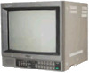
...and packing materials. When shipping the unit to be removed with a cloth lightly dampened with a soft cloth. PVM-1340 On safety • Operate the unit only on the carton. Never use strong solvents such as illustrated on 120 V AC. • Should any solid object or liquid fall into... in which to transport the unit. As a safety precaution, unplug the unit before operating it any questions about this unit, contact your authorized Sony dealer. 000000 O For the customers in Canada This apparatus complies with the Class A limits for several days or more. • To disconnect...
...and packing materials. When shipping the unit to be removed with a cloth lightly dampened with a soft cloth. PVM-1340 On safety • Operate the unit only on the carton. Never use strong solvents such as illustrated on 120 V AC. • Should any solid object or liquid fall into... in which to transport the unit. As a safety precaution, unplug the unit before operating it any questions about this unit, contact your authorized Sony dealer. 000000 O For the customers in Canada This apparatus complies with the Class A limits for several days or more. • To disconnect...
Operating Instructions
Page 5
...connected to occur in the underscan mode. This allows an extended use with this connector is obtained with all three cathodes driven with the COLOR TEMP selector. Super Fine Pitch Trinitron picutre tube (PVM-1344Q/PVM-1342Q only) The Super Fine Pitch Trinitron picture tube (0.25 mm... aperture grill) gives high resolution picture. When used as the levels to be checked simultaneously in the underscan mode are received,...
...connected to occur in the underscan mode. This allows an extended use with this connector is obtained with all three cathodes driven with the COLOR TEMP selector. Super Fine Pitch Trinitron picutre tube (PVM-1344Q/PVM-1342Q only) The Super Fine Pitch Trinitron picture tube (0.25 mm... aperture grill) gives high resolution picture. When used as the levels to be checked simultaneously in the underscan mode are received,...
Operating Instructions
Page 7
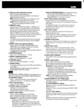
...VTR connectors are visible. 15 BLUE ONLY button Depress to turn the monitor off the red and green signals. 1 BIAS and GAIN adjustment controls Used for the NTSC3.5t3 and NTSC4.4.3 color system. The response indicator flashes when the above buttons or the RESET button is displayed as ANALOG/... The APERTURE, CHROMA, PHASE control settings have no effect on the pictures of the screen at the lowlight with these controls. Y/C/VTR: for PVM-1444OM). To release the memorized levels and restore the factory set levels (memorized levels for a signal fed through the LINE A connectors.
...VTR connectors are visible. 15 BLUE ONLY button Depress to turn the monitor off the red and green signals. 1 BIAS and GAIN adjustment controls Used for the NTSC3.5t3 and NTSC4.4.3 color system. The response indicator flashes when the above buttons or the RESET button is displayed as ANALOG/... The APERTURE, CHROMA, PHASE control settings have no effect on the pictures of the screen at the lowlight with these controls. Y/C/VTR: for PVM-1444OM). To release the memorized levels and restore the factory set levels (memorized levels for a signal fed through the LINE A connectors.
Operating Instructions
Page 11
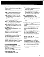
...position, 9300°K or 6500°K. 5 COMPO (component)/RGB selector Set to COMPO to the "control S" output of a VCR or another monitor by using a connecting cord (miniplug-,-.miniplug). 9 ANALOG RGB/COMPONENT connectors (BNC type) Ft/R-Y IN, G/Y IN, B/B-Y IN: To monitor the analog R/G/B signal... a suitable microphone amplifier. AUDIO IN (phono jack): Connect to the audio output of a VCR or to the video output of a Sony BetaCam video camera. Connect to the R-Y/Y/B-Y component signal inputs of a video camera. For component signal, connect to the SYNC input of a ...
...position, 9300°K or 6500°K. 5 COMPO (component)/RGB selector Set to COMPO to the "control S" output of a VCR or another monitor by using a connecting cord (miniplug-,-.miniplug). 9 ANALOG RGB/COMPONENT connectors (BNC type) Ft/R-Y IN, G/Y IN, B/B-Y IN: To monitor the analog R/G/B signal... a suitable microphone amplifier. AUDIO IN (phono jack): Connect to the audio output of a VCR or to the video output of a Sony BetaCam video camera. Connect to the R-Y/Y/B-Y component signal inputs of a video camera. For component signal, connect to the SYNC input of a ...
Operating Instructions
Page 12
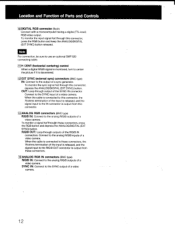
..., depress the ANALOG/DIGITAL (EXT SYNC) button. SYNC IN: Connect to the analog R/G/B outputs of the SYNC IN connector. Note For connection, be sure to use an optional SMF-520 connecting cable. 11 H CENT (horizontal centering) control When a digital R/G/B signal is monitored, turn to center the picture if it is decentered...
..., depress the ANALOG/DIGITAL (EXT SYNC) button. SYNC IN: Connect to the analog R/G/B outputs of the SYNC IN connector. Note For connection, be sure to use an optional SMF-520 connecting cable. 11 H CENT (horizontal centering) control When a digital R/G/B signal is monitored, turn to center the picture if it is decentered...
Operating Instructions
Page 14
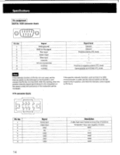
... ---. GND GND GND GND 14 If the specific intensity function, such as H-SYNC (TTL level) Note If the intensity function of Pin No. 6 is not used , set the internal switch on the Qd board to the B position, and connect the Pin No. 6 to the GND. Specifications Pin assignment DIGITAL RGB connector... H-SYNC V-SYNC Signal level Ground Ground Positive polarity (TTL level) t t t Positive or negative polarity (TTL level) Same polarity as that of an IBM microcomputer, is used , set the internal switch on the Qd board to the A position, and feed the intensity control signal to Pin No. 6.
... ---. GND GND GND GND 14 If the specific intensity function, such as H-SYNC (TTL level) Note If the intensity function of Pin No. 6 is not used , set the internal switch on the Qd board to the B position, and connect the Pin No. 6 to the GND. Specifications Pin assignment DIGITAL RGB connector... H-SYNC V-SYNC Signal level Ground Ground Positive polarity (TTL level) t t t Positive or negative polarity (TTL level) Same polarity as that of an IBM microcomputer, is used , set the internal switch on the Qd board to the A position, and feed the intensity control signal to Pin No. 6.
