
User Manual
Page 54
...only. WARNING Owner's Record The model and serial numbers are located on a circuit different from that to radio communications. Refer to Part 15 of the FCC Rules. Model No. To avoid electrical shock, do not expose the unit to provide reasonable protection against ...-29 Daniels Parkway, PMB 330 Fort Myers, Florida 33912 Declaration of Conformity Trade Name: Model: Responsible Party: Address: Telephone Number: SONY PFM-42B1/42B2 Sony Electronics Inc. 680 Kinderkamack Road, Oradell NJ 07649 U.S.A. 201-930-6972 interference to radio or television reception, which can radiate radio ...
...only. WARNING Owner's Record The model and serial numbers are located on a circuit different from that to radio communications. Refer to Part 15 of the FCC Rules. Model No. To avoid electrical shock, do not expose the unit to provide reasonable protection against ...-29 Daniels Parkway, PMB 330 Fort Myers, Florida 33912 Declaration of Conformity Trade Name: Model: Responsible Party: Address: Telephone Number: SONY PFM-42B1/42B2 Sony Electronics Inc. 680 Kinderkamack Road, Oradell NJ 07649 U.S.A. 201-930-6972 interference to radio or television reception, which can radiate radio ...
User Manual
Page 55
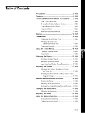
... and Function of Parts and Controls ....... 7 (GB) Front / Rear / Right Side 7 (GB) 1 (standby) Switch / Indicator Section 8 (GB) Control Button Section (Rear 8 (GB) Connector Panel 9 (GB) Remote Commander RM-42B 11 (GB) Caution 13 (GB) Connections 14 (GB) Connecting the AC Power Cord 14 (GB) Attaching the ferrite core (PFM-42B2/42B2E only 14...
... and Function of Parts and Controls ....... 7 (GB) Front / Rear / Right Side 7 (GB) 1 (standby) Switch / Indicator Section 8 (GB) Control Button Section (Rear 8 (GB) Connector Panel 9 (GB) Remote Commander RM-42B 11 (GB) Caution 13 (GB) Connections 14 (GB) Connecting the AC Power Cord 14 (GB) Attaching the ferrite core (PFM-42B2/42B2E only 14...
User Manual
Page 57
...sunlight, excessive dust, mechanical vibration or shock. • When you continue to display the same image on the screen for a long period of time, part of that may block the ventilation holes. • Do not install the unit in a location near materials (curtains, draperies) that image may remain on... surfaces (rugs, blankets, etc.) or near heat sources such as radiators or air ducts, or in which to avoid burning this unit, contact your authorized Sony dealer. 5 (GB) Never pull the cord itself. • When the unit is located on the screen. On the PDP (Plasma Display Panel) &#...
...sunlight, excessive dust, mechanical vibration or shock. • When you continue to display the same image on the screen for a long period of time, part of that may block the ventilation holes. • Do not install the unit in a location near materials (curtains, draperies) that image may remain on... surfaces (rugs, blankets, etc.) or near heat sources such as radiators or air ducts, or in which to avoid burning this unit, contact your authorized Sony dealer. 5 (GB) Never pull the cord itself. • When the unit is located on the screen. On the PDP (Plasma Display Panel) &#...
User Manual
Page 59
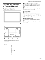
... Controls Front / Rear / Right Side Front 1 Location and Function of Parts and Controls 1 1 (standby) switch / indicator section For details on the 1 (standby) switch / indicator section, see "1 (standby) Switch / Indicator Section" on page 8 (GB). 2 Control button section ...
... Controls Front / Rear / Right Side Front 1 Location and Function of Parts and Controls 1 1 (standby) switch / indicator section For details on the 1 (standby) switch / indicator section, see "1 (standby) Switch / Indicator Section" on page 8 (GB). 2 Control button section ...
User Manual
Page 60
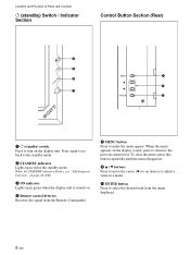
... a menu. 3 ENTER button Press to select the desired item from the Remote Commander. 1 MENU button Press to make the menu appear. Location and Function of Parts and Controls 1 (standby) Switch / Indicator Section Control Button Section (Rear) 4 3 1 2 2 1 3 1 1 (standby) switch Press to turn on the display screen, press to return to the previous...
... a menu. 3 ENTER button Press to select the desired item from the Remote Commander. 1 MENU button Press to make the menu appear. Location and Function of Parts and Controls 1 (standby) Switch / Indicator Section Control Button Section (Rear) 4 3 1 2 2 1 3 1 1 (standby) switch Press to turn on the display screen, press to return to the previous...
User Manual
Page 61
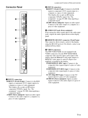
This display also accepts an HD analog component (Y/PB/PR) signal. For details, contact your authorized Sony dealer. 5 VIDEO connectors The PFM-42B1E/42B2E are not equipped with VIDEO connectors. Y/C IN (Mini DIN 4-pin): Connects to the audio output of a computer or a piece of video... an audio signal. COMPOSITE OUT (BNC-type): Connects to the audio output of a computer or a piece of video equipment. Location and Function of Parts and Controls 2 INPUT2 connectors RGB/YUV (D-sub 15-pin): Connects to the RGB signal or component (YUV) signal output of a computer or a piece...
This display also accepts an HD analog component (Y/PB/PR) signal. For details, contact your authorized Sony dealer. 5 VIDEO connectors The PFM-42B1E/42B2E are not equipped with VIDEO connectors. Y/C IN (Mini DIN 4-pin): Connects to the audio output of a computer or a piece of video... an audio signal. COMPOSITE OUT (BNC-type): Connects to the audio output of a computer or a piece of video equipment. Location and Function of Parts and Controls 2 INPUT2 connectors RGB/YUV (D-sub 15-pin): Connects to the RGB signal or component (YUV) signal output of a computer or a piece...

User Manual
Page 62
... connect the CONTROL S connector on a video device or display to the composite signal output connector on the other device. 10 (GB) Location and Function of Parts and Controls Component Input Adaptor (with Control S) BKM-B12 (Not supplied) The VIDEO connectors are Slot-in connectors. Connect the CONTROL S OUT connector on this...
... connect the CONTROL S connector on a video device or display to the composite signal output connector on the other device. 10 (GB) Location and Function of Parts and Controls Component Input Adaptor (with Control S) BKM-B12 (Not supplied) The VIDEO connectors are Slot-in connectors. Connect the CONTROL S OUT connector on this...

User Manual
Page 63
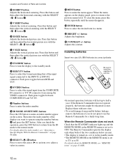
... slot Install a LAN card or PC memory card as needed. 3 Ethernet connector Connect to the Y/ C output connector of an image device. Location and Function of Parts and Controls Remote Commander RM-42B 1 qs 2 3 qd 4 5 qf 6 Y/C 1 qg VIDEO IN COMPOSITE qh qj 7 qk 8 ql 2 9 w; 0 wa qa 3 4 5 1 VIDEO IN connector Y/C connector (Mini DIN...
... slot Install a LAN card or PC memory card as needed. 3 Ethernet connector Connect to the Y/ C output connector of an image device. Location and Function of Parts and Controls Remote Commander RM-42B 1 qs 2 3 qd 4 5 qf 6 Y/C 1 qg VIDEO IN COMPOSITE qh qj 7 qk 8 ql 2 9 w; 0 wa qa 3 4 5 1 VIDEO IN connector Y/C connector (Mini DIN...
User Manual
Page 64
... the index number, see "Operating a Specific Display With the Remote Commander" on the display panel, press to return to select the format matching that of Parts and Controls 8 H SHIFT button Adjusts the horizontal centering. When the menu appears on page 44 (GB). button Adjusts the brightness. qd RGB/YUV button Press...
... the index number, see "Operating a Specific Display With the Remote Commander" on the display panel, press to return to select the format matching that of Parts and Controls 8 H SHIFT button Adjusts the horizontal centering. When the menu appears on page 44 (GB). button Adjusts the brightness. qd RGB/YUV button Press...
User Manual
Page 74
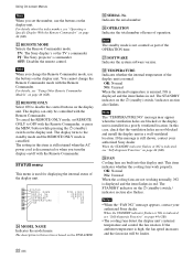
... PJ: The Sony projector's commander OFF: Disables the remote control. The display turns to disable the control buttons on page 44 (GB). The description in red. ek TEMPERATURE Indicates whether the internal temperature of the OPERATION time. In this display unit. The STANDBY indicator on the PFM-42B2E. es ..., set the number, use the buttons on the 1 (standby) switch / indicator section also flashes. Note The standby mode is not counted as part of the display unit is disconnected or when you turn the display on page 44 (GB). When the STANDBY indicator flashes or NG is high...
... PJ: The Sony projector's commander OFF: Disables the remote control. The display turns to disable the control buttons on page 44 (GB). The description in red. ek TEMPERATURE Indicates whether the internal temperature of the OPERATION time. In this display unit. The STANDBY indicator on the PFM-42B2E. es ..., set the number, use the buttons on the 1 (standby) switch / indicator section also flashes. Note The standby mode is not counted as part of the display unit is disconnected or when you turn the display on page 44 (GB). When the STANDBY indicator flashes or NG is high...


