User Manual
Page 54
... Declaration of Conformity Trade Name: Model: Responsible Party: Address: Telephone Number: SONY PFM-42B1/42B2 Sony Electronics Inc. 680 Kinderkamack Road, Oradell NJ 07649 U.S.A. 201-930-6972 interference to radio or television reception, which the receiver is connected. • Consult the dealer or an experienced radio/TV technician for a Class B digital device, pursuant to Part 15 of the FCC Rules. These...
... Declaration of Conformity Trade Name: Model: Responsible Party: Address: Telephone Number: SONY PFM-42B1/42B2 Sony Electronics Inc. 680 Kinderkamack Road, Oradell NJ 07649 U.S.A. 201-930-6972 interference to radio or television reception, which the receiver is connected. • Consult the dealer or an experienced radio/TV technician for a Class B digital device, pursuant to Part 15 of the FCC Rules. These...
User Manual
Page 55
...) Control Button Section (Rear 8 (GB) Connector Panel 9 (GB) Remote Commander RM-42B 11 (GB) Caution 13 (GB) Connections 14 (GB) Connecting the AC Power Cord 14 (GB) Attaching the ferrite core (PFM-42B2/42B2E only 14 (GB) Connection Example 15 (GB) Using On-screen Menus 20 (GB) Operating Through Menus 20 (GB) GB Menu Guide 20 (GB) Watching the Picture 24 (GB) Switching the Input Signal 24 (GB) Switching the Display Mode...
...) Control Button Section (Rear 8 (GB) Connector Panel 9 (GB) Remote Commander RM-42B 11 (GB) Caution 13 (GB) Connections 14 (GB) Connecting the AC Power Cord 14 (GB) Attaching the ferrite core (PFM-42B2/42B2E only 14 (GB) Connection Example 15 (GB) Using On-screen Menus 20 (GB) Operating Through Menus 20 (GB) GB Menu Guide 20 (GB) Watching the Picture 24 (GB) Switching the Input Signal 24 (GB) Switching the Display Mode...
User Manual
Page 57
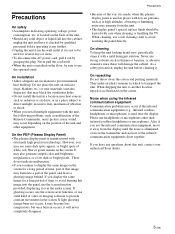
... microphones. Precautions • Because of white, red, blue or green remain on surfaces (rugs, blankets, etc.) or near the display. As a safety precaution, unplug the unit before operating it . On the PDP (Plasma Display Panel) • The plasma display panel is made, when this image into the panel, use strong solvents such as malfunction of the Remote Commander, noisy picture, noisy sound, may burn into the cabinet, unplug the...
... microphones. Precautions • Because of white, red, blue or green remain on surfaces (rugs, blankets, etc.) or near the display. As a safety precaution, unplug the unit before operating it . On the PDP (Plasma Display Panel) • The plasma display panel is made, when this image into the panel, use strong solvents such as malfunction of the Remote Commander, noisy picture, noisy sound, may burn into the cabinet, unplug the...
User Manual
Page 58
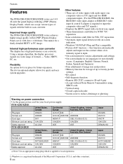
... picture settings. • ID control • Self-diagnosis function • Remote (RS-232C) connector (D-sub 9-pin) • Accepts infrared Sony Remote Commanders using SIRCS code. • Vertical setup • Closed caption decoder • Screen saver to reduce afterimage or ghosting. This makes for quick and easy system upgrades. Flexibility An option slot is input. • On-screen menu for various adjustments and settings • On-screen display in six languages for user...
... picture settings. • ID control • Self-diagnosis function • Remote (RS-232C) connector (D-sub 9-pin) • Accepts infrared Sony Remote Commanders using SIRCS code. • Vertical setup • Closed caption decoder • Screen saver to reduce afterimage or ghosting. This makes for quick and easy system upgrades. Flexibility An option slot is input. • On-screen menu for various adjustments and settings • On-screen display in six languages for user...

User Manual
Page 59
... 1 (standby) switch / indicator section, see "1 (standby) Switch / Indicator Section" on page 8 (GB). 2 Control button section For details on the control button section, see "Connector Panel" on page 8 (GB). 3 Carrying handles 4 -AC IN socket Connect the supplied AC power cord to this socket and to a wall outlet. Right side 6 7 (GB) Rear 2 3 4 5 The shaded areas shown in red and the display turns to the standby mode. 5 Stand installation hooks Use these hooks to install the stand (not supplied). 6 Connector panel For...
... 1 (standby) switch / indicator section, see "1 (standby) Switch / Indicator Section" on page 8 (GB). 2 Control button section For details on the control button section, see "Connector Panel" on page 8 (GB). 3 Carrying handles 4 -AC IN socket Connect the supplied AC power cord to this socket and to a wall outlet. Right side 6 7 (GB) Rear 2 3 4 5 The shaded areas shown in red and the display turns to the standby mode. 5 Stand installation hooks Use these hooks to install the stand (not supplied). 6 Connector panel For...
User Manual
Page 61
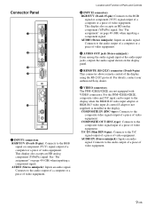
... (GB) when inputting a component signal. Connects to the RGB signal or component (YUV) signal output of a computer or a piece of video equipment. Location and Function of Parts and Controls 2 INPUT2 connectors RGB/YUV (D-sub 15-pin): Connects to the audio output of a computer or a piece of video equipment. 3 AUDIO OUT jack (Stereo minijack) From among the audio signals input at the audio input jacks, outputs the audio signal shown on the display panel. 4 REMOTE (RS-232C...
... (GB) when inputting a component signal. Connects to the RGB signal or component (YUV) signal output of a computer or a piece of video equipment. Location and Function of Parts and Controls 2 INPUT2 connectors RGB/YUV (D-sub 15-pin): Connects to the audio output of a computer or a piece of video equipment. 3 AUDIO OUT jack (Stereo minijack) From among the audio signals input at the audio input jacks, outputs the audio signal shown on the display panel. 4 REMOTE (RS-232C...

User Manual
Page 62
... Control S) BKMB12. Y/C IN (Video Input) connector (Mini-DIN 4pin): Connects to the Y/C output connector on the video device. 2 CONTROL S IN/OUT (Control S signal input/ output) connector (Minijack) You can connect the CONTROL S connector on a video device or display to this connector, you can replace the VIDEO connectors with the Component Input Adaptor (with the VIDEO Input & Control S Adaptor BKM-B13. Location and Function of Parts and Controls Component Input Adaptor (with Control S) BKM-B12 (Not supplied) The VIDEO...
... Control S) BKMB12. Y/C IN (Video Input) connector (Mini-DIN 4pin): Connects to the Y/C output connector on the video device. 2 CONTROL S IN/OUT (Control S signal input/ output) connector (Minijack) You can connect the CONTROL S connector on a video device or display to this connector, you can replace the VIDEO connectors with the Component Input Adaptor (with the VIDEO Input & Control S Adaptor BKM-B13. Location and Function of Parts and Controls Component Input Adaptor (with Control S) BKM-B12 (Not supplied) The VIDEO...

User Manual
Page 63
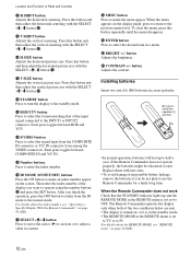
... to the Y/ C output connector of an image device. COMPOSITE connector (Pinjack): Connect to the composite output connector of an image device. 2 PC card slot Install a LAN card or PC memory card as needed. 3 Ethernet connector Connect to turn on the display. 2 DISPLAY button Displays the input signal information and the time at the top of the display panel. Location and Function of Parts and Controls Remote Commander RM-42B 1 qs 2 3 qd 4 5 qf 6 Y/C 1 qg VIDEO IN COMPOSITE...
... to the Y/ C output connector of an image device. COMPOSITE connector (Pinjack): Connect to the composite output connector of an image device. 2 PC card slot Install a LAN card or PC memory card as needed. 3 Ethernet connector Connect to turn on the display. 2 DISPLAY button Displays the input signal information and the time at the top of the display panel. Location and Function of Parts and Controls Remote Commander RM-42B 1 qs 2 3 qd 4 5 qf 6 Y/C 1 qg VIDEO IN COMPOSITE...
User Manual
Page 64
... button Adjusts the vertical centering. qh ID MODE (ON/SET/OFF) buttons Press the ON button to operate using the number buttons qg and press the SET button. After you want to make the menu appear. Installing batteries Insert two size AA (R6) batteries in a menu. When the menu appears on page 45 (GB). Location and Function of the input signal connected to adjust a value in a menu. BRIGHT +/- qs STANDBY button Press to turn the display to...
... button Adjusts the vertical centering. qh ID MODE (ON/SET/OFF) buttons Press the ON button to operate using the number buttons qg and press the SET button. After you want to make the menu appear. Installing batteries Insert two size AA (R6) batteries in a menu. When the menu appears on page 45 (GB). Location and Function of the input signal connected to adjust a value in a menu. BRIGHT +/- qs STANDBY button Press to turn the display to...
User Manual
Page 67
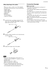
... that this unit to various pieces of equipment using the cable. A loose connection may cause hum and other noise. • To disconnect the cable, pull it click. AUDIO (INPUT1) AUDIO (INPUT2) AUDIO OUT REMOTE Y/C IN (VIDEO) AUDIO IN (VIDEO) 1 Attach the ferrite core (black) to the end of the cable closer to the PFM-42B2/42B2E, closing it firmly until your hear it out by...
... that this unit to various pieces of equipment using the cable. A loose connection may cause hum and other noise. • To disconnect the cable, pull it click. AUDIO (INPUT1) AUDIO (INPUT2) AUDIO OUT REMOTE Y/C IN (VIDEO) AUDIO IN (VIDEO) 1 Attach the ferrite core (black) to the end of the cable closer to the PFM-42B2/42B2E, closing it firmly until your hear it out by...

User Manual
Page 69
The following shows the connection example where the Component Input Adaptor (with Control S) BKM-B12 (Not supplied) has been installed. Connections VCR, game machine, DVD player, etc. to YUV/GBR to component signal output INPUT 3 Y/G U/B V/R CONTROL S IN OUT to Control S out to Control S in 17 (GB) Connection Example: The Component Input Adaptor (with Control S) BKMB12 (Not supplied) has been installed.
The following shows the connection example where the Component Input Adaptor (with Control S) BKM-B12 (Not supplied) has been installed. Connections VCR, game machine, DVD player, etc. to YUV/GBR to component signal output INPUT 3 Y/G U/B V/R CONTROL S IN OUT to Control S out to Control S in 17 (GB) Connection Example: The Component Input Adaptor (with Control S) BKMB12 (Not supplied) has been installed.

User Manual
Page 70
For a connection example of the BKM-B30NW network adaptor (Not supplied), see the BKMB30NW instruction manual. 18 (GB) OUT IN Y/C IN CONTROL S VIDEO to Control S out to video output VCR, game machine, DVD player, etc. IN OUT COMPOSITE to Y/C IN or COMPOSITE IN to Control S in The following shows a connection example where the Video Input & Control S Adaptor BKM-B13 (Not supplied) has been installed. Connections Connection Example: The Video Input & Control S Adaptor BKM-B13 (Not supplied) has been installed.
For a connection example of the BKM-B30NW network adaptor (Not supplied), see the BKMB30NW instruction manual. 18 (GB) OUT IN Y/C IN CONTROL S VIDEO to Control S out to video output VCR, game machine, DVD player, etc. IN OUT COMPOSITE to Y/C IN or COMPOSITE IN to Control S in The following shows a connection example where the Video Input & Control S Adaptor BKM-B13 (Not supplied) has been installed. Connections Connection Example: The Video Input & Control S Adaptor BKM-B13 (Not supplied) has been installed.
User Manual
Page 73
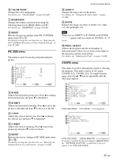
... or LB ZOOM, "- - - -" appears and you have installed the Network Adaptor (BKM-B30NW), the "NETWORK ADAPTOR" is not displayed. qa V SIZE Adjusts the vertical picture size. VGA : OF F C LOSED CAP T I L L : SMP T E : CENTER ws P OWE R C O N T R O L SCREEN SAVER wd wf SE L ECT S E T ENTER E N D MENU PFM-42B1/42B1E: "YUV LEVEL" is added but it down. qd RESET Restores the factory settings in the PFM-42B1/42B1E. 21 (GB) Note When you...
... or LB ZOOM, "- - - -" appears and you have installed the Network Adaptor (BKM-B30NW), the "NETWORK ADAPTOR" is not displayed. qa V SIZE Adjusts the vertical picture size. VGA : OF F C LOSED CAP T I L L : SMP T E : CENTER ws P OWE R C O N T R O L SCREEN SAVER wd wf SE L ECT S E T ENTER E N D MENU PFM-42B1/42B1E: "YUV LEVEL" is added but it down. qd RESET Restores the factory settings in the PFM-42B1/42B1E. 21 (GB) Note When you...
User Manual
Page 75
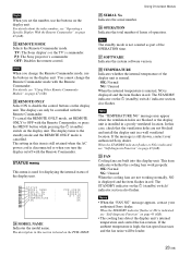
...: The Sony display's or the TV's commander PJ: The Sony projector's commander OFF: Disables the remote control. The STANDBY indicator on the 1 (standby) switch / indicator section also flashes. el FAN Cooling fans are not blocked and install the display unit in this display unit. es REMOTE MODE Selects the Remote Commander mode. Using On-screen Menus eg SERIAL No. The setting in a well ventilated location. eh OPERATION Indicates the total number of...
...: The Sony display's or the TV's commander PJ: The Sony projector's commander OFF: Disables the remote control. The STANDBY indicator on the 1 (standby) switch / indicator section also flashes. el FAN Cooling fans are not blocked and install the display unit in this display unit. es REMOTE MODE Selects the Remote Commander mode. Using On-screen Menus eg SERIAL No. The setting in a well ventilated location. eh OPERATION Indicates the total number of...
User Manual
Page 76
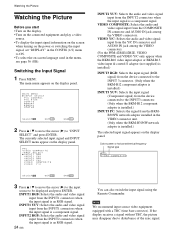
... signal. INPUT1 RGB: Selects the audio and video signal input from the INPUT2 connectors when the input signal is an RGB signal. Watching the Picture Watching the Picture Before you start • Turn on the display. • Turn on the connected equipment and play a video source. • To display the input signal information on the screen when turning on the power or switching the input signal, set "DISPLAY" in the CONFIG (1/2) menu to disturbance of the sync signal. VIDEO Y/C: Selects the audio and video signal input...
... signal. INPUT1 RGB: Selects the audio and video signal input from the INPUT2 connectors when the input signal is an RGB signal. Watching the Picture Watching the Picture Before you start • Turn on the display. • Turn on the connected equipment and play a video source. • To display the input signal information on the screen when turning on the power or switching the input signal, set "DISPLAY" in the CONFIG (1/2) menu to disturbance of the sync signal. VIDEO Y/C: Selects the audio and video signal input...
User Manual
Page 79
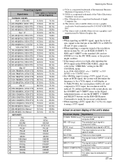
... inputting a computer signal at 31.5kHz/59.9Hz, the screen phase will display at the resolution shown in item No. 29, set H SIZE, H SHIFT, V SIZE and V SHIFT to the standard (00) and set to ×1 in the PIC SIZE menu, or the picture might oscillate. • If the image color is too light after inputting the DVD signal in the PFM-42B1/42B1E, adjust the color in the "CHROMA" setting in the CONFIG menu...
... inputting a computer signal at 31.5kHz/59.9Hz, the screen phase will display at the resolution shown in item No. 29, set H SIZE, H SHIFT, V SIZE and V SHIFT to the standard (00) and set to ×1 in the PIC SIZE menu, or the picture might oscillate. • If the image color is too light after inputting the DVD signal in the PFM-42B1/42B1E, adjust the color in the "CHROMA" setting in the CONFIG menu...

User Manual
Page 89
... changes the position of connected equipment such as DSS, Cable box, video decks, etc. The following menu appears on the display panel. The CONFIG (1/2) menu appears on the display panel. Note The followings are alternative procedures for a long time, this , or to attempt to fix it, a screen saver function has been provided with 4:3 video source (conventional TV broadcast), 3 Video game sources, 4 DVD on -screen menus etc., of connected equipment such as DSS, Cable box, video...
... changes the position of connected equipment such as DSS, Cable box, video decks, etc. The following menu appears on the display panel. The CONFIG (1/2) menu appears on the display panel. Note The followings are alternative procedures for a long time, this , or to attempt to fix it, a screen saver function has been provided with 4:3 video source (conventional TV broadcast), 3 Video game sources, 4 DVD on -screen menus etc., of connected equipment such as DSS, Cable box, video...

User Manual
Page 92
... F C LOSED CAP T I ON : OF F COLOR SYS T EM : AUTO YUV LEVEL : SMP T E SCREEN F I NG : OF F 5 Press v / V to "POWER CONTROL" and press ENTER. Signal specification for using the power saving function The sync signal should be the RGB signal input to the 13th pin of time until the change to the power saving mode after 10 minutes if there is reduced and you can view the display unit while saving energy...
... F C LOSED CAP T I ON : OF F COLOR SYS T EM : AUTO YUV LEVEL : SMP T E SCREEN F I NG : OF F 5 Press v / V to "POWER CONTROL" and press ENTER. Signal specification for using the power saving function The sync signal should be the RGB signal input to the 13th pin of time until the change to the power saving mode after 10 minutes if there is reduced and you can view the display unit while saving energy...

User Manual
Page 99
... the table below. Using Other Remote Commander Models Remote Commander model RM-854 REMOTE MODE setting TV Input selection INPUT1 RGB INPUT2 - On-screen information DISPLAY RM-921 TV RGB1 RGB2 LINE MENU ENTER SELECT+M SELECT-m - - - Phase PHASE+/- Using Other Remote Commander Models The following operations can be carried out using other Remote Commander models. • Power on/off • Input selection • Menu operations • Picture adjustments: contrast, phase and chroma • On-screen display on...
... the table below. Using Other Remote Commander Models Remote Commander model RM-854 REMOTE MODE setting TV Input selection INPUT1 RGB INPUT2 - On-screen information DISPLAY RM-921 TV RGB1 RGB2 LINE MENU ENTER SELECT+M SELECT-m - - - Phase PHASE+/- Using Other Remote Commander Models The following operations can be carried out using other Remote Commander models. • Power on/off • Input selection • Menu operations • Picture adjustments: contrast, phase and chroma • On-screen display on...
User Manual
Page 100
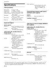
... (×2) 5 Vp-p General AUDIO OUT Stereo minijack 500 mVrms, high impedance Power requirements 100 V to 240 V AC, 50/60 Hz, REMOTE (RS-232C) D-sub 9-pin (×1) PFM-42B1/42B1E: 4.5 A to 1.8 A PFM-42B2/42B2E: 4.2 A to the display when the BKM-B10 video input adaptor or BKM-B13 video input & control S adaptor (not supplied) is installed in the display unit. 48 (GB) Specifications Specifications Video processing Preset signal See page 27...
... (×2) 5 Vp-p General AUDIO OUT Stereo minijack 500 mVrms, high impedance Power requirements 100 V to 240 V AC, 50/60 Hz, REMOTE (RS-232C) D-sub 9-pin (×1) PFM-42B1/42B1E: 4.5 A to 1.8 A PFM-42B2/42B2E: 4.2 A to the display when the BKM-B10 video input adaptor or BKM-B13 video input & control S adaptor (not supplied) is installed in the display unit. 48 (GB) Specifications Specifications Video processing Preset signal See page 27...


