
VAIO User Guide
Page 3
Contents Welcome 5 Locating Controls and Connectors 7 Front Panel Overview 7 Back Panel Overview 10 VAIO Action Setup 13 Shortcut Keys 13 To Change the Sony Software Window Design 15 VAIO AV Applications 17 Overview of Preinstalled Software 17 DigitalPrint Software 19 DVgate Software 27 MovieShaker Software 30 PictureGear Software 37 Smart Capture Software 40 SonicStage Software 49 VisualFlow Software 56 Configuring Your VAIO Computer 59 Hard Disk Drive Partition 59 i.LINK (IEEE1394) Compatibility 60 To Enable Ethernet Connectivity 61 3
Contents Welcome 5 Locating Controls and Connectors 7 Front Panel Overview 7 Back Panel Overview 10 VAIO Action Setup 13 Shortcut Keys 13 To Change the Sony Software Window Design 15 VAIO AV Applications 17 Overview of Preinstalled Software 17 DigitalPrint Software 19 DVgate Software 27 MovieShaker Software 30 PictureGear Software 37 Smart Capture Software 40 SonicStage Software 49 VisualFlow Software 56 Configuring Your VAIO Computer 59 Hard Disk Drive Partition 59 i.LINK (IEEE1394) Compatibility 60 To Enable Ethernet Connectivity 61 3
VAIO User Guide
Page 7
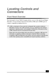
... includes Universal Serial Bus (USB) and i.LINK® ports to connect compatible peripheral devices. ✍ i.LINK is a trademark of your VAIO Computer allows access to your compatible i.LINK device for information on the software applications, operating system, and compatible i.LINK devices. The i.LINK connection ... an optical or hard disk drive, confirm their operating system compatibility and required operating conditions. 7 Locating Controls and Connectors Front Panel Overview The front panel of Sony used only to the documentation that a product contains an IEEE1394 connection.
... includes Universal Serial Bus (USB) and i.LINK® ports to connect compatible peripheral devices. ✍ i.LINK is a trademark of your VAIO Computer allows access to your compatible i.LINK device for information on the software applications, operating system, and compatible i.LINK devices. The i.LINK connection ... an optical or hard disk drive, confirm their operating system compatibility and required operating conditions. 7 Locating Controls and Connectors Front Panel Overview The front panel of Sony used only to the documentation that a product contains an IEEE1394 connection.
System Reference Manual
Page 50
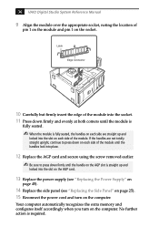
...slot is required. Your computer automatically recognizes the extra memory and configures itself accordingly when you turn on each side of the module. 36 VAIO Digital Studio System Reference ... seated. ✍ When the module is fully seated, the handles on the computer. Latch Edge Connector 10 Carefully but firmly insert the edge of the module into the slot on... the AGP card. 13 Replace the power supply (see "Replacing the Power Supply" on page 45). 14 Replace the side panel (see "Replacing the Side Panel...
...slot is required. Your computer automatically recognizes the extra memory and configures itself accordingly when you turn on each side of the module. 36 VAIO Digital Studio System Reference ... seated. ✍ When the module is fully seated, the handles on the computer. Latch Edge Connector 10 Carefully but firmly insert the edge of the module into the slot on... the AGP card. 13 Replace the power supply (see "Replacing the Power Supply" on page 45). 14 Replace the side panel (see "Replacing the Side Panel...
System Reference Manual
Page 53
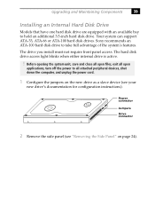
... with an available bay to take full advantage of the system's features. Sony recommends an ATA-100 hard disk drive to hold an additional 3.5-inch hard disk drive. Power connector Jumpers Drive connector 2 Remove the side panel (see your new drive's documentation for configuration instructions). Before opening the system...applications, turn off the power to all attached peripheral devices, shut down the computer, and unplug the power cord. 1 Configure the jumpers on the new drive as a slave device (see "Removing the Side Panel" on page 24). Your system can support ATA-33, ATA-66 or ATA...
... with an available bay to take full advantage of the system's features. Sony recommends an ATA-100 hard disk drive to hold an additional 3.5-inch hard disk drive. Power connector Jumpers Drive connector 2 Remove the side panel (see your new drive's documentation for configuration instructions). Before opening the system...applications, turn off the power to all attached peripheral devices, shut down the computer, and unplug the power cord. 1 Configure the jumpers on the new drive as a slave device (see "Removing the Side Panel" on page 24). Your system can support ATA-33, ATA-66 or ATA...
System Reference Manual
Page 56
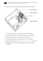
42 VAIO Digital Studio System Reference Manual 10 Push in on your computer. C E B D A Drive connectors Power connectors Tab Disk drive holder 11 Connect the inner drive cable connector (B) to the first drive. 12 Connect the outer drive cable connector (C) to the second drive. 13 Connect the first power connector (D) to the first drive. 14 Connect the second power connector (E) to the second drive. 15 Replace the side panel (see "Replacing the Side Panel" on page 25). 16 Reconnect the power cord to the system and then turn on the tab (A) to securely latch the holder to the chassis.
42 VAIO Digital Studio System Reference Manual 10 Push in on your computer. C E B D A Drive connectors Power connectors Tab Disk drive holder 11 Connect the inner drive cable connector (B) to the first drive. 12 Connect the outer drive cable connector (C) to the second drive. 13 Connect the first power connector (D) to the first drive. 14 Connect the second power connector (E) to the second drive. 15 Replace the side panel (see "Replacing the Side Panel" on page 25). 16 Reconnect the power cord to the system and then turn on the tab (A) to securely latch the holder to the chassis.
System Reference Manual
Page 61
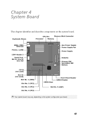
Keyboard, Mouse CPU Fan Memory Stick Connector Processor Memory USB3, USB4 Ethernet Printer, i.LINK 1394 Header 3 Serial Port, Mic In, Line In Line Out CD-In (not used) Aux-In (not used) ... No. 2 (PCI) Slot No. 3 (PCI) Slot No. 4 (PCI) Aux Power Supply Power Supply Fan Power Supply Diskette Primary IDE Secondary IDE Battery CMOS Clear Front Panel Header USB23 Header Slot No. 5 (AGP) ✍ Your system board may vary, depending on the system board. Chapter 4 System Board This chapter identifies and describes...
Keyboard, Mouse CPU Fan Memory Stick Connector Processor Memory USB3, USB4 Ethernet Printer, i.LINK 1394 Header 3 Serial Port, Mic In, Line In Line Out CD-In (not used) Aux-In (not used) ... No. 2 (PCI) Slot No. 3 (PCI) Slot No. 4 (PCI) Aux Power Supply Power Supply Fan Power Supply Diskette Primary IDE Secondary IDE Battery CMOS Clear Front Panel Header USB23 Header Slot No. 5 (AGP) ✍ Your system board may vary, depending on the system board. Chapter 4 System Board This chapter identifies and describes...
System Reference Manual
Page 89
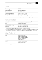
... In jack Audio L/R In jack * On models equipped with Giga Pocket features. Specifications 75 Audio Sound chip Wave synthesis Sound effects Audio sampling rate Rear panel connectors SiS 7012 Software synthesis DirectX® software Up to 48 kHz at 16-bits Mic (for microphone) Line In (from stereo audio source) Headphones (for...
... In jack Audio L/R In jack * On models equipped with Giga Pocket features. Specifications 75 Audio Sound chip Wave synthesis Sound effects Audio sampling rate Rear panel connectors SiS 7012 Software synthesis DirectX® software Up to 48 kHz at 16-bits Mic (for microphone) Line In (from stereo audio source) Headphones (for...
System Reference Manual
Page 94
... P passwords, user and supervisor 64 PCI add-in card 26 side panel 24 slot cover 37 replacing 25 side panel 25 replacing lithium battery 30 resolution - See Also communications monitor - 80 VAIO Digital Studio System Reference Manual I i.LINK connector 6 I/O address map 69 I/O connectors i.LINK 13 keyboard and mouse 10 mic, line in card 28 system...
... P passwords, user and supervisor 64 PCI add-in card 26 side panel 24 slot cover 37 replacing 25 side panel 25 replacing lithium battery 30 resolution - See Also communications monitor - 80 VAIO Digital Studio System Reference Manual I i.LINK connector 6 I/O address map 69 I/O connectors i.LINK 13 keyboard and mouse 10 mic, line in card 28 system...
