
System Reference Manual
Page 12
... Port 70 Headphones, Line In, Mic Jacks 71 i.LINK Headers 72 CD-IN Header 73 AUX-IN Header 74 Video Header 75 xii VAIO Digital Studio™ System Reference Manual Chapter 3 - Removing, Installing, and Replacing Components 27 Removing the Side Cover 28 Replacing the Side Cover 29... Internal Hard Disk Drive 45 To prepare a startup disk (PCV-RX490TV model only 45 To install a 3.5-inch internal hard disk drive (all models 46 To set up the new hard drive with the startup disk (PCV-RX490TV model only 49 To identify the additional hard disk space for Giga Pocket use (PCV-RX490TV model...
... Port 70 Headphones, Line In, Mic Jacks 71 i.LINK Headers 72 CD-IN Header 73 AUX-IN Header 74 Video Header 75 xii VAIO Digital Studio™ System Reference Manual Chapter 3 - Removing, Installing, and Replacing Components 27 Removing the Side Cover 28 Replacing the Side Cover 29... Internal Hard Disk Drive 45 To prepare a startup disk (PCV-RX490TV model only 45 To install a 3.5-inch internal hard disk drive (all models 46 To set up the new hard drive with the startup disk (PCV-RX490TV model only 49 To identify the additional hard disk space for Giga Pocket use (PCV-RX490TV model...

System Reference Manual
Page 14
xiv VAIO Digital Studio™ System Reference Manual Audio ...111 Communications 112 Giga Pocket I/O (PCV-RX490TV only 112 I/O and Expansion Slots 112 Floppy Disk Drive and Controller 113 Hard Drives and Controllers 113 Optical Drives 114 System BIOS 116 Index 117
xiv VAIO Digital Studio™ System Reference Manual Audio ...111 Communications 112 Giga Pocket I/O (PCV-RX490TV only 112 I/O and Expansion Slots 112 Floppy Disk Drive and Controller 113 Hard Drives and Controllers 113 Optical Drives 114 System BIOS 116 Index 117

System Reference Manual
Page 21
... disk drive activity. On (red) indicates hard disk drive activity. On (red) indicates optical drive activity. Indicators All Models Identifying Components 7 Floppy disk drive access Hard disk drive access Optical disc drive access Power/Stand by Indicator Power/Stand by indicator Floppy disk drive access indicator Optical drive access indicator Hard disk drive access indicator Description Stand by (red) indicates the computer is...
... disk drive activity. On (red) indicates hard disk drive activity. On (red) indicates optical drive activity. Indicators All Models Identifying Components 7 Floppy disk drive access Hard disk drive access Optical disc drive access Power/Stand by Indicator Power/Stand by indicator Floppy disk drive access indicator Optical drive access indicator Hard disk drive access indicator Description Stand by (red) indicates the computer is...
System Reference Manual
Page 31
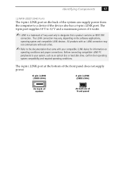
Before connecting compatible i.LINK PC peripherals to designate that came with your system, such as an optical disc or hard disk drive, confirm their operating system compatibility and required operating conditions. The i.LINK connection may not communicate with an i.LINK ... trademark of Sony used only to your compatible i.LINK device for information on the software applications, operating system and compatible i.LINK devices. Identifying Components 17 i.LINK® (IEEE1394) Ports The 6-pin i.LINK port on the back of the system can supply power from the computer to the ...
Before connecting compatible i.LINK PC peripherals to designate that came with your system, such as an optical disc or hard disk drive, confirm their operating system compatibility and required operating conditions. The i.LINK connection may not communicate with an i.LINK ... trademark of Sony used only to your compatible i.LINK device for information on the software applications, operating system and compatible i.LINK devices. Identifying Components 17 i.LINK® (IEEE1394) Ports The 6-pin i.LINK port on the back of the system can supply power from the computer to the ...
System Reference Manual
Page 59
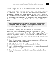
For the PCV-RX490TV, Sony recommends an ATA-100 hard disk drive to hold an additional 3.5-inch hard disk drive. Removing, Installing, and Replacing Components 45 Installing a 3.5-inch Internal Hard Disk Drive Models that have only one hard disk drive have an available bay to take full advantage of the system's features. The drive you add a second hard disk drive to your computer, Sony recommends creating...
For the PCV-RX490TV, Sony recommends an ATA-100 hard disk drive to hold an additional 3.5-inch hard disk drive. Removing, Installing, and Replacing Components 45 Installing a 3.5-inch Internal Hard Disk Drive Models that have only one hard disk drive have an available bay to take full advantage of the system's features. The drive you add a second hard disk drive to your computer, Sony recommends creating...
System Reference Manual
Page 60
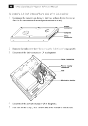
Power connector Jumpers Drive connector 2 Remove the side cover (see "Removing the Side Cover" on page 28). 3 Disconnect the drive connector (A in diagram). 5 Pull out on the new drive as a slave device (see your drive's documentation for configuration instructions). Drive connector A B C Power supply connector Tab Disk drive holder 4 Disconnect the power connector (B in diagram). 46 VAIO Digital Studio™ System Reference Manual To install a 3.5-inch internal hard disk drive (all models) 1 Configure the jumpers on the tab (C) that secures the drive holder to the chassis.
Power connector Jumpers Drive connector 2 Remove the side cover (see "Removing the Side Cover" on page 28). 3 Disconnect the drive connector (A in diagram). 5 Pull out on the new drive as a slave device (see your drive's documentation for configuration instructions). Drive connector A B C Power supply connector Tab Disk drive holder 4 Disconnect the power connector (B in diagram). 46 VAIO Digital Studio™ System Reference Manual To install a 3.5-inch internal hard disk drive (all models) 1 Configure the jumpers on the tab (C) that secures the drive holder to the chassis.

System Reference Manual
Page 62
...PCV-RX490TV will automatically recognize the new drive and configure itself accordingly when you turn on your new hard drive. Format and partition the new drive following page to the system and then turn it will cause functionality problems to the Giga Pocket card. 16 Reconnect the power cord to finish installing your computer. 48 VAIO Digital Studio...™ System Reference Manual 10 Push in on the tab (A) to securely latch the holder to the second drive. 15 Replace the side cover (see "Replacing ...
...PCV-RX490TV will automatically recognize the new drive and configure itself accordingly when you turn on your new hard drive. Format and partition the new drive following page to the system and then turn it will cause functionality problems to the Giga Pocket card. 16 Reconnect the power cord to finish installing your computer. 48 VAIO Digital Studio...™ System Reference Manual 10 Push in on the tab (A) to securely latch the holder to the second drive. 15 Replace the side cover (see "Replacing ...
System Reference Manual
Page 63
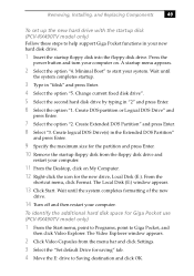
... new hard drive with the startup disk (PCV-RX490TV model only) Follow these steps to Giga Pocket, and then click Video Explorer. A startup menu appears. 2 Select the option "4. Wait until the system completes formatting of the new drive. 14 Turn off and then restart your computer. Create... the system completes startup. 3 Type in your computer on My Computer. 12 Right-click the icon for the new drive, Local Disk (E:). To identify the additional hard disk space for saving" tab. 4 Move the E: drive to start your computer. 11 From the Desktop, click on . From the shortcut menu, click...
... new hard drive with the startup disk (PCV-RX490TV model only) Follow these steps to Giga Pocket, and then click Video Explorer. A startup menu appears. 2 Select the option "4. Wait until the system completes formatting of the new drive. 14 Turn off and then restart your computer. Create... the system completes startup. 3 Type in your computer on My Computer. 12 Right-click the icon for the new drive, Local Disk (E:). To identify the additional hard disk space for saving" tab. 4 Move the E: drive to start your computer. 11 From the Desktop, click on . From the shortcut menu, click...
System Reference Manual
Page 64
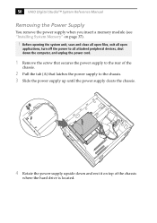
...open files, exit all open applications, turn off the power to all attached peripheral devices, shut down and rest it on page 37). ! 50 VAIO Digital Studio™ System Reference Manual Removing the Power Supply You remove the power supply when you insert a memory module (see "Installing System Memory" on top... to the chassis. 3 Slide the power supply up until the power supply clears the chassis. A 4 Rotate the power supply upside down the computer, and unplug the power cord. 1 Remove the screw that latches the power supply to the rear of the chassis where the hard drive is located.
...open files, exit all open applications, turn off the power to all attached peripheral devices, shut down and rest it on page 37). ! 50 VAIO Digital Studio™ System Reference Manual Removing the Power Supply You remove the power supply when you insert a memory module (see "Installing System Memory" on top... to the chassis. 3 Slide the power supply up until the power supply clears the chassis. A 4 Rotate the power supply upside down the computer, and unplug the power cord. 1 Remove the screw that latches the power supply to the rear of the chassis where the hard drive is located.

System Reference Manual
Page 68
... LED Connects to the hard disk drive access light on the front panel SLEEP (not used) PWR Connects to the power-on switch on the front panel A 20-pin header with only 10 wires is removed for the key) that provides connections to various front panel functions. 54 VAIO Digital Studio™ System Reference Manual...
... LED Connects to the hard disk drive access light on the front panel SLEEP (not used) PWR Connects to the power-on switch on the front panel A 20-pin header with only 10 wires is removed for the key) that provides connections to various front panel functions. 54 VAIO Digital Studio™ System Reference Manual...
System Reference Manual
Page 107
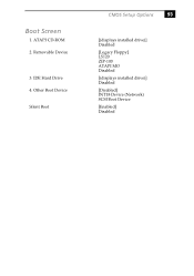
Boot Screen 1. Removable Device 3. Other Boot Device Silent Boot CMOS Setup Options 93 [(displays installed drive)] Disabled [Legacy Floppy] LS120 ZIP-100 ATAPI MO Disabled [(displays installed drive)] Disabled [Disabled] INT18 Device (Network) SCSI Boot Device [Enabled] Disabled ATAPI CD-ROM 2. IDE Hard Drive 4.
Boot Screen 1. Removable Device 3. Other Boot Device Silent Boot CMOS Setup Options 93 [(displays installed drive)] Disabled [Legacy Floppy] LS120 ZIP-100 ATAPI MO Disabled [(displays installed drive)] Disabled [Disabled] INT18 Device (Network) SCSI Boot Device [Enabled] Disabled ATAPI CD-ROM 2. IDE Hard Drive 4.
System Reference Manual
Page 112
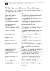
... more than 15 PCI conflict errors are detected. This message is already in use. The designated primary boot device (hard disk drive, floppy disk drive, CD-ROM drive, or network drive) could not be logged. 98 VAIO Digital Studio™ System Reference Manual PCI Configuration Status and Error Messages The following is already in use. The Clear CMOS...
... more than 15 PCI conflict errors are detected. This message is already in use. The designated primary boot device (hard disk drive, floppy disk drive, CD-ROM drive, or network drive) could not be logged. 98 VAIO Digital Studio™ System Reference Manual PCI Configuration Status and Error Messages The following is already in use. The Clear CMOS...
System Reference Manual
Page 127
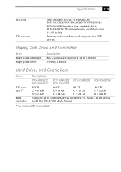
One available slot in PCV-RX462DS/ PCV-RX463DS/PCV-RX465DS/PCV-RX470DS/ PCV-RX480DS models. Hard Drives and Controllers Drive IDE hard drive* EIDE controller Description PCV-RX462DS PCV-RX465DS PCV-RX480DS PCV-RX490TV PCV-RX463DS PCV-RX470DS 40 GB C = 16 GB D = 24 GB 60 GB C = 16 GB D = 44 GB 80 GB C = 16 GB D = 64 GB 80 GB C = 12 GB D = 68 GB Supports up to four EIDE drives (supports PIO...
One available slot in PCV-RX462DS/ PCV-RX463DS/PCV-RX465DS/PCV-RX470DS/ PCV-RX480DS models. Hard Drives and Controllers Drive IDE hard drive* EIDE controller Description PCV-RX462DS PCV-RX465DS PCV-RX480DS PCV-RX490TV PCV-RX463DS PCV-RX470DS 40 GB C = 16 GB D = 24 GB 60 GB C = 16 GB D = 44 GB 80 GB C = 16 GB D = 64 GB 80 GB C = 12 GB D = 68 GB Supports up to four EIDE drives (supports PIO...

System Reference Manual
Page 132
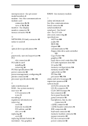
...and error 98 See Also slots F fan connectors 69 CPU-FAN 69 PWR-FAN 69 fax card - See graphics graphics specifications 110 H hard drive specifications 113 header - See modem card fax/modem - See front panel header headphones, line in, mic connectors 71 I i.LINK connector ... cache specifications 110 lithium battery, replacing 34 lithium ion battery disposal vii safety precautions vii M map - 118 VAIO Digital Studio™ System Reference Manual installing additional 3.5 drive 45 DVD-ROM drive performance of 11, 12 IDE connectors 59 IEEE1394 - See modem card FCC Part 68 vi floppy disk...
...and error 98 See Also slots F fan connectors 69 CPU-FAN 69 PWR-FAN 69 fax card - See graphics graphics specifications 110 H hard drive specifications 113 header - See modem card fax/modem - See front panel header headphones, line in, mic connectors 71 I i.LINK connector ... cache specifications 110 lithium battery, replacing 34 lithium ion battery disposal vii safety precautions vii M map - 118 VAIO Digital Studio™ System Reference Manual installing additional 3.5 drive 45 DVD-ROM drive performance of 11, 12 IDE connectors 59 IEEE1394 - See modem card FCC Part 68 vi floppy disk...
System Reference Manual
Page 133
...ii serial port - See display monitor connector 14 mouse connector 13, 62 N NETWORK (D-Link) connector 65 notice to users ii O optical drive specifications 114 P passwords, user and supervisor 96 PCI slot connectors 57 PCI add-in card 32 slot cover 43 replacing 29 cover 29 replacing...See I/O slot slot cover, removing 43 specifications AGP bus 109 audio 111 BIOS 116 chipset 109 communications 112 floppy disk drive and controller 113 Giga Pocket 112 graphics 110 hard drives and controllers 113 I /O connectors 13 icons 11 recording ii regulatory information v removing cover 28 memory module 41 PCI ...
...ii serial port - See display monitor connector 14 mouse connector 13, 62 N NETWORK (D-Link) connector 65 notice to users ii O optical drive specifications 114 P passwords, user and supervisor 96 PCI slot connectors 57 PCI add-in card 32 slot cover 43 replacing 29 cover 29 replacing...See I/O slot slot cover, removing 43 specifications AGP bus 109 audio 111 BIOS 116 chipset 109 communications 112 floppy disk drive and controller 113 Giga Pocket 112 graphics 110 hard drives and controllers 113 I /O connectors 13 icons 11 recording ii regulatory information v removing cover 28 memory module 41 PCI ...
Marketing Specifications
Page 1
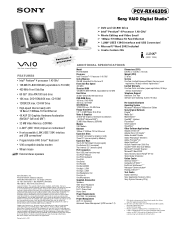
...instance. Non-metric weights and measurements are trademarks of the hardware and software in this disclaimer. CD-ROM CD-RW Drive 12X8X32X max. PCV-RX463DS Sony VAIO Digital Studio™ Video Audio Integrated Operation Ppernotcieusmso4r FEATURES • Intel® Pentium® 4 processor 1.40 GHz†... to hard drive capacity. DVD-ROM 40X max. All products with an i.LINK connector may make any warranty or representation with any combination of varying software packages and add-on the Sony Desktop Computer are registered trademarks of Sony. This personal computer is ...
...instance. Non-metric weights and measurements are trademarks of the hardware and software in this disclaimer. CD-ROM CD-RW Drive 12X8X32X max. PCV-RX463DS Sony VAIO Digital Studio™ Video Audio Integrated Operation Ppernotcieusmso4r FEATURES • Intel® Pentium® 4 processor 1.40 GHz†... to hard drive capacity. DVD-ROM 40X max. All products with an i.LINK connector may make any warranty or representation with any combination of varying software packages and add-on the Sony Desktop Computer are registered trademarks of Sony. This personal computer is ...


