
System Reference Manual
Page 12
... Aux Power Headers 60 Keyboard and Mouse Ports 62 USB Ports and USB Header 63 Ethernet Port 65 Serial , Printer, and i.LINK Ports 65 Fan Headers 69 Game Port 70 Headphones, Line In, Mic Jacks 71 i.LINK Headers 72 CD-IN Header 73 AUX-IN Header 74 Video Header 75...all models 46 To set up the new hard drive with the startup disk (PCV-RX490TV model only 49 To identify the additional hard disk space for Giga Pocket use (PCV-RX490TV model only 49 Removing the Power Supply 50 Replacing the Power Supply 51 Chapter 4 - xii VAIO Digital Studio™ System Reference Manual Chapter 3 -
... Aux Power Headers 60 Keyboard and Mouse Ports 62 USB Ports and USB Header 63 Ethernet Port 65 Serial , Printer, and i.LINK Ports 65 Fan Headers 69 Game Port 70 Headphones, Line In, Mic Jacks 71 i.LINK Headers 72 CD-IN Header 73 AUX-IN Header 74 Video Header 75...all models 46 To set up the new hard drive with the startup disk (PCV-RX490TV model only 49 To identify the additional hard disk space for Giga Pocket use (PCV-RX490TV model only 49 Removing the Power Supply 50 Replacing the Power Supply 51 Chapter 4 - xii VAIO Digital Studio™ System Reference Manual Chapter 3 -

System Reference Manual
Page 67
Chapter 4 System Board This chapter identifies each component on the system board and provides a detailed description of each header, connector, and jumper on the system board. Keyboard, Mouse Processor Memory CPU Fan Power Supply Fan USB1, USB2, Ethernet Serial, Printer, iLink 1394 Header 2 Game, Mic In, Line In, Line Out 1394 Header 3 Aux-In Video Aux Power Supply Power Supply Secondary IDE Primary IDE Diskette Slot 4 (AGP) Battery CD-In Slot No. 3 (PCI) Slot No. 2 (PCI) Slot No. 1 (PCI) CMOS Clear Front Panel Header USB23 Header 53
Chapter 4 System Board This chapter identifies each component on the system board and provides a detailed description of each header, connector, and jumper on the system board. Keyboard, Mouse Processor Memory CPU Fan Power Supply Fan USB1, USB2, Ethernet Serial, Printer, iLink 1394 Header 2 Game, Mic In, Line In, Line Out 1394 Header 3 Aux-In Video Aux Power Supply Power Supply Secondary IDE Primary IDE Diskette Slot 4 (AGP) Battery CD-In Slot No. 3 (PCI) Slot No. 2 (PCI) Slot No. 1 (PCI) CMOS Clear Front Panel Header USB23 Header 53
System Reference Manual
Page 83
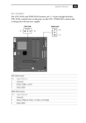
CPU-FAN controls the cooling fan on the CPU. PWR-FAN controls the cooling fan in the power supply. System Board 69 Fan Headers The CPU-FAN and PWR-FAN headers are 1 x 3-pin straight headers. CPU-FAN 1 3 PWR-FAN 3 1 CPU-FAN header Pin Signal Name 1 Ground 2 FAN_CTRL (+12V) 3 FAN_SEN PWR-FAN header Pin Signal Name 1 Ground 2 FAN_CTRL [0 V(S3) , 2 V(S1), 12 V(S0)] 3 FAN_SEN
CPU-FAN controls the cooling fan on the CPU. PWR-FAN controls the cooling fan in the power supply. System Board 69 Fan Headers The CPU-FAN and PWR-FAN headers are 1 x 3-pin straight headers. CPU-FAN 1 3 PWR-FAN 3 1 CPU-FAN header Pin Signal Name 1 Ground 2 FAN_CTRL (+12V) 3 FAN_SEN PWR-FAN header Pin Signal Name 1 Ground 2 FAN_CTRL [0 V(S3) , 2 V(S1), 12 V(S0)] 3 FAN_SEN

System Reference Manual
Page 131
... - See processor D display, power management 23 disposal of discs 3, 4, 114, 115 chipset specifications 109 CLR CMOS Jumper 76 CMOS - See Serial communications, specifications 112 computer lithium ion battery vii computer safety information ii configuring power management 23 connectors 4-pin on modem card 78, 79 AUX-IN 74 CD-IN 73... fan 69 game 70 headphones, line in, mic 71 i.LINK 8, 65, 72 IDE 59 keyboard 62 line 78, 79 modem card 78, 79 monitor 14 ...
... - See processor D display, power management 23 disposal of discs 3, 4, 114, 115 chipset specifications 109 CLR CMOS Jumper 76 CMOS - See Serial communications, specifications 112 computer lithium ion battery vii computer safety information ii configuring power management 23 connectors 4-pin on modem card 78, 79 AUX-IN 74 CD-IN 73... fan 69 game 70 headphones, line in, mic 71 i.LINK 8, 65, 72 IDE 59 keyboard 62 line 78, 79 modem card 78, 79 monitor 14 ...

System Reference Manual
Page 132
... specifications 110 memory module connector 56 removing 41 specifications 110 messages error 97 status and error 98 See Also slots F fan connectors 69 CPU-FAN 69 PWR-FAN 69 fax card - See modem card FCC Part 68 vi floppy disk drive connector 55 specifications 113 front panel header ... 14 serial port 1 14 telephone and line 16 USB ports 13, 63 I/O slot covering 44 I /O address map and memory map memory - 118 VAIO Digital Studio™ System Reference Manual installing additional 3.5 drive 45 DVD-ROM drive performance of 11, 12 IDE connectors 59 IEEE1394 - See front panel header headphones,...
... specifications 110 memory module connector 56 removing 41 specifications 110 messages error 97 status and error 98 See Also slots F fan connectors 69 CPU-FAN 69 PWR-FAN 69 fax card - See modem card FCC Part 68 vi floppy disk drive connector 55 specifications 113 front panel header ... 14 serial port 1 14 telephone and line 16 USB ports 13, 63 I/O slot covering 44 I /O address map and memory map memory - 118 VAIO Digital Studio™ System Reference Manual installing additional 3.5 drive 45 DVD-ROM drive performance of 11, 12 IDE connectors 59 IEEE1394 - See front panel header headphones,...
System Reference Manual
Page 133
... processor 109, 110 status and error messages 98 supervisor password 96 system board AUX-IN connector 74 CD-IN connector 73 CLR CMOS Jumper 76 fan connectors 69 front panel header 54 game connector 70 headphones, line in card 32 slot cover 43 replacing 29 cover 29 replacing lithium battery 34...
... processor 109, 110 status and error messages 98 supervisor password 96 system board AUX-IN connector 74 CD-IN connector 73 CLR CMOS Jumper 76 fan connectors 69 front panel header 54 game connector 70 headphones, line in card 32 slot cover 43 replacing 29 cover 29 replacing lithium battery 34...


