Reference Manual
Page 2
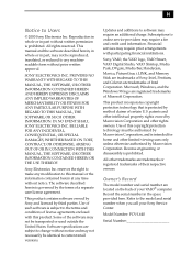
... the model and serial number when you call your VAIO® computer. All other rights owners. SONY ELECTRONICS INC. IN NO EVENT SHALL SONY ELECTRONICS INC. Use of such software is prohibited. Sony, VAIO, the VAIO logo, VAIO Smart, VAIO Digital Studio, VAIO Slimtop, Media Park, DVgate, Media Bar, Handycam, Mavica... and other limited viewing uses only unless otherwise authorized by method claims of a separate user license agreement. Model Number: PCV-L640 Serial Number This manual and the software described herein, in whole or in the space provided here. Intel, Pentium, ...
... the model and serial number when you call your VAIO® computer. All other rights owners. SONY ELECTRONICS INC. IN NO EVENT SHALL SONY ELECTRONICS INC. Use of such software is prohibited. Sony, VAIO, the VAIO logo, VAIO Smart, VAIO Digital Studio, VAIO Slimtop, Media Park, DVgate, Media Bar, Handycam, Mavica... and other limited viewing uses only unless otherwise authorized by method claims of a separate user license agreement. Model Number: PCV-L640 Serial Number This manual and the software described herein, in whole or in the space provided here. Intel, Pentium, ...
Reference Manual
Page 3
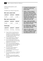
... nm 780-795 nm ❑ To prevent fire or shock hazard, do not open . To change the backup battery, contact your desktop to beam. ! iii VAIO Computer Reference Manual Safety Information and Caution CD-RW Laser Diode Properties Max. Danger - Visible and invisible laser radiation when open. Avoid direct exposure to rain...
... nm 780-795 nm ❑ To prevent fire or shock hazard, do not open . To change the backup battery, contact your desktop to beam. ! iii VAIO Computer Reference Manual Safety Information and Caution CD-RW Laser Diode Properties Max. Danger - Visible and invisible laser radiation when open. Avoid direct exposure to rain...
Reference Manual
Page 5
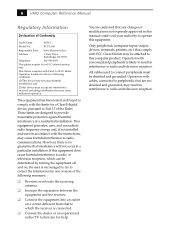
This device complies with Part 15 of Conformity Trade Name: SONY Model No.: PCV-L640 Responsible Party: Sony Electronics Inc. Operation is subject to the two following measures: : ❑ Reorient or relocate the receiving antenna. ❑ Increase... Operation with noncompliant peripherals is connected. ❑ Consult the dealer or an experienced radio/TV technician for FCC-related matters only. v VAIO Computer Reference Manual Regulatory Information Declaration of FCC Rules. These limits are cautioned that interference will not occur in accordance with FCC Class B limits...
This device complies with Part 15 of Conformity Trade Name: SONY Model No.: PCV-L640 Responsible Party: Sony Electronics Inc. Operation is subject to the two following measures: : ❑ Reorient or relocate the receiving antenna. ❑ Increase... Operation with noncompliant peripherals is connected. ❑ Consult the dealer or an experienced radio/TV technician for FCC-related matters only. v VAIO Computer Reference Manual Regulatory Information Declaration of FCC Rules. These limits are cautioned that interference will not occur in accordance with FCC Class B limits...
Reference Manual
Page 7
... contact: CRTC Terrasses de la Chaudiére, Tour centrale 1 promenade du Portage, 5 étage Hull PQ K1A 0N2. For the Sony Service Center nearest you, call 1-888-476-6972 in the United States or 1-800-961-7669 in this device may be prohibited. Discard used...de 100°C. Évacuer promptement la batterie us ées selon les directives du fabricant. ! vii VAIO Computer Reference Manual Telephone Consumer Guidelines (Canada) Please refer to your nearest Sony Service Center or Factory Service Center. ✍ In some areas the disposal of explosion if battery is incorrectly ...
... contact: CRTC Terrasses de la Chaudiére, Tour centrale 1 promenade du Portage, 5 étage Hull PQ K1A 0N2. For the Sony Service Center nearest you, call 1-888-476-6972 in the United States or 1-800-961-7669 in this device may be prohibited. Discard used...de 100°C. Évacuer promptement la batterie us ées selon les directives du fabricant. ! vii VAIO Computer Reference Manual Telephone Consumer Guidelines (Canada) Please refer to your nearest Sony Service Center or Factory Service Center. ✍ In some areas the disposal of explosion if battery is incorrectly ...
Reference Manual
Page 12
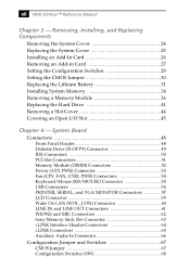
... 34 Removing a Memory Module 36 Replacing the Hard Drive 41 Removing a Slot Cover 44 Covering an Open I/O Slot 45 Chapter 4 - xii VAIO Slimtop™ Reference Manual Chapter 3 - System Board Connectors 48 Front Panel Header 48 Diskette Drive (FLOPPY) Connector 49 IDE Connectors 50 PCI Slot Connectors...57 LCD Connector 59 Wake On LAN (WOL_CON) Connector 60 LINE IN and LINE OUT Connectors 61 PHONE and MIC Connectors 62 Sony Memory Stick Slot Connector 63 i.LINK Interface Header Connectors 64 i.LINK Connectors 65 Auxiliary Audio In Connector 66 Configuration Jumper and Switches...
... 34 Removing a Memory Module 36 Replacing the Hard Drive 41 Removing a Slot Cover 44 Covering an Open I/O Slot 45 Chapter 4 - xii VAIO Slimtop™ Reference Manual Chapter 3 - System Board Connectors 48 Front Panel Header 48 Diskette Drive (FLOPPY) Connector 49 IDE Connectors 50 PCI Slot Connectors...57 LCD Connector 59 Wake On LAN (WOL_CON) Connector 60 LINE IN and LINE OUT Connectors 61 PHONE and MIC Connectors 62 Sony Memory Stick Slot Connector 63 i.LINK Interface Header Connectors 64 i.LINK Connectors 65 Auxiliary Audio In Connector 66 Configuration Jumper and Switches...
Reference Manual
Page 15
Internal components are identified in Chapters 3, 4, and 5 of the VAIO® Computer. Chapter 1 Identifying Components The following sections identify and describe each component that is visible from the exterior of this manual. 1
Internal components are identified in Chapters 3, 4, and 5 of the VAIO® Computer. Chapter 1 Identifying Components The following sections identify and describe each component that is visible from the exterior of this manual. 1
Reference Manual
Page 18
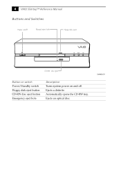
4 VAIO Slimtop™ Reference Manual Buttons and Switches Power on/off Manual eject hole Floppy disk eject FD DISC HD CD-RW disc eject Button or switch Power/Standby switch Floppy disk eject button CD-RW disc eject button Emergency eject hole Description Turns system power on and off. Automatically opens the CD-RW tray. SHA0003.VSD Ejects an optical disc. Ejects a diskette.
4 VAIO Slimtop™ Reference Manual Buttons and Switches Power on/off Manual eject hole Floppy disk eject FD DISC HD CD-RW disc eject Button or switch Power/Standby switch Floppy disk eject button CD-RW disc eject button Emergency eject hole Description Turns system power on and off. Automatically opens the CD-RW tray. SHA0003.VSD Ejects an optical disc. Ejects a diskette.
Reference Manual
Page 20
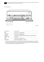
...the device. Controls headphone volume. * To connect to headphones. Connects to a 6-pin i.LINK device, use the i.LINK connector on the back of the system. 6 VAIO Slimtop™ Reference Manual Connectors FD DISC HD MIC PHONES VOLUME i.LINK USB SHA0005.VSD Connector MIC PHONES i.LINK® (IEEE-1394)* USB VOLUME Description Connects... to digital devices that have a 4-pin i.LINK connector. Connects to microphone. A 6-pin i.LINK connector can supply power from the computer to the device if the device also has a 6-pin i.LINK connector.
...the device. Controls headphone volume. * To connect to headphones. Connects to a 6-pin i.LINK device, use the i.LINK connector on the back of the system. 6 VAIO Slimtop™ Reference Manual Connectors FD DISC HD MIC PHONES VOLUME i.LINK USB SHA0005.VSD Connector MIC PHONES i.LINK® (IEEE-1394)* USB VOLUME Description Connects... to digital devices that have a 4-pin i.LINK connector. Connects to microphone. A 6-pin i.LINK connector can supply power from the computer to the device if the device also has a 6-pin i.LINK connector.
Reference Manual
Page 22
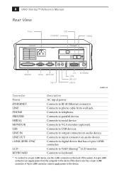
8 VAIO Slimtop™ Reference Manual Rear View Power LINE ETHERNET PHONE PRINTER SERIAL MONITOR LINE USB LINE IN OUT I.LINK S400 LCD PHONE KEYBOARD PRINTER SERIAL MONITOR .... Connects to keyboard. * To connect to output connector on the back of the system. A 6-pin i.LINK connector can supply power from wall jack. Connects to VAIO Slimtop™ LCD monitor. Connects to parallel device. Connects to a 6-pin i.LINK device, use the i.LINK connector on audio device. Connects to input connector on audio...
8 VAIO Slimtop™ Reference Manual Rear View Power LINE ETHERNET PHONE PRINTER SERIAL MONITOR LINE USB LINE IN OUT I.LINK S400 LCD PHONE KEYBOARD PRINTER SERIAL MONITOR .... Connects to keyboard. * To connect to output connector on the back of the system. A 6-pin i.LINK connector can supply power from wall jack. Connects to VAIO Slimtop™ LCD monitor. Connects to parallel device. Connects to a 6-pin i.LINK device, use the i.LINK connector on audio device. Connects to input connector on audio...
Reference Manual
Page 24
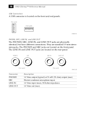
... microphone input. 1.0 Vrms input (max), 50 Kohm impedance. 1.0 Vrms out (max). The PHONES and MIC jacks are located on the front and real panels. 10 VAIO Slimtop™ Reference Manual USB Connectors A USB connector is located on the rear panel.
... microphone input. 1.0 Vrms input (max), 50 Kohm impedance. 1.0 Vrms out (max). The PHONES and MIC jacks are located on the front and real panels. 10 VAIO Slimtop™ Reference Manual USB Connectors A USB connector is located on the rear panel.
Reference Manual
Page 25
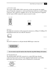
... i.LINK (IEEE-1394) On rear panel On front panel KY0087.VSD Ethernet The Ethernet connector on the rear panel can be used for the supplied VAIO Smart convertible keyboard with wheel mouse, and a standard PS/2 keyboard. 1 6 2 5 3 4 KY0002.VS MAN009.VSD KY0004.VSD ! Identifying Components 11 i.... connects to a 10Base-T/100Base-TX Fast Ethernet network via an RJ-45 connector. Do not connect any LCD monitor other than the Sony VAIO Slimtop LCD monitor. KEYBOARD/MOUSE The KEYBOARD/MOUSE connector is a 40-pin female MDR-type connector. LCD The LCD connector is a mini...
... i.LINK (IEEE-1394) On rear panel On front panel KY0087.VSD Ethernet The Ethernet connector on the rear panel can be used for the supplied VAIO Smart convertible keyboard with wheel mouse, and a standard PS/2 keyboard. 1 6 2 5 3 4 KY0002.VS MAN009.VSD KY0004.VSD ! Identifying Components 11 i.... connects to a 10Base-T/100Base-TX Fast Ethernet network via an RJ-45 connector. Do not connect any LCD monitor other than the Sony VAIO Slimtop LCD monitor. KEYBOARD/MOUSE The KEYBOARD/MOUSE connector is a 40-pin female MDR-type connector. LCD The LCD connector is a mini...
Reference Manual
Page 26
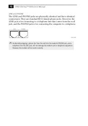
However, the LINE jack is for connecting the computer to a telephone. They are physically identical and have identical connections. 12 VAIO Slimtop™ Reference Manual LINE and PHONE The LINE and PHONE jacks are standard RJ-11 female phone jacks. However, the modem will not damage the ...
However, the LINE jack is for connecting the computer to a telephone. They are physically identical and have identical connections. 12 VAIO Slimtop™ Reference Manual LINE and PHONE The LINE and PHONE jacks are standard RJ-11 female phone jacks. However, the modem will not damage the ...
Reference Manual
Page 28
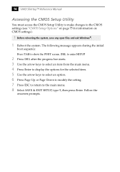
14 VAIO Slimtop™ Reference Manual Accessing the CMOS Setup Utility You must access the CMOS Setup Utility to make changes to the CMOS settings (see "CMOS Setup ...
14 VAIO Slimtop™ Reference Manual Accessing the CMOS Setup Utility You must access the CMOS Setup Utility to make changes to the CMOS settings (see "CMOS Setup ...
Reference Manual
Page 30
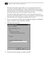
... (in minutes) that you want to elapse before your hard disks turn off when your computer is running on AC power. The display reactivates when you move the mouse or press a key. 16 VAIO Slimtop™ Reference Manual The Turn off monitor option allows you to specify the period of inactivity... (in minutes) that you want to elapse before your monitor turns off when your computer is running on AC power. 4 To save a new ...
... (in minutes) that you want to elapse before your hard disks turn off when your computer is running on AC power. The display reactivates when you move the mouse or press a key. 16 VAIO Slimtop™ Reference Manual The Turn off monitor option allows you to specify the period of inactivity... (in minutes) that you want to elapse before your monitor turns off when your computer is running on AC power. 4 To save a new ...
Reference Manual
Page 32
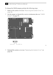
18 VAIO Slimtop™ Reference Manual To change the CMOS jumper, perform the following steps: 1 Remove the system cover (see "Removing the System Cover" on page 24). 2 Set the jumper as directed by a service technician (also see "Replacing the System Cover" on page 67). O1 2 3 4 5 6 N 123 Normal CMOS Clear KY0 3 Reinstall the system cover (see "CMOS Jumper" on page 25).
18 VAIO Slimtop™ Reference Manual To change the CMOS jumper, perform the following steps: 1 Remove the system cover (see "Removing the System Cover" on page 24). 2 Set the jumper as directed by a service technician (also see "Replacing the System Cover" on page 67). O1 2 3 4 5 6 N 123 Normal CMOS Clear KY0 3 Reinstall the system cover (see "CMOS Jumper" on page 25).
Reference Manual
Page 34
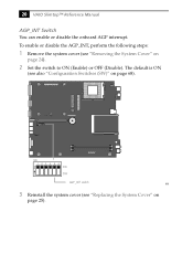
The default is ON (see "Replacing the System Cover" on page 25). 20 VAIO Slimtop™ Reference Manual AGP_INT Switch You can enable or disable the onboard AGP interrupt. O1 2 3 4 5 6 N SW 123456 O N ON OFF AGP_INT switch KY0 3 Reinstall the system cover (see also "Configuration Switches (SW)" on page 24). 2 Set the switch to ON (Enable) or OFF (Disable). To enable or disable the AGP_INT, perform the following steps: 1 Remove the system cover (see "Removing the System Cover" on page 68).
The default is ON (see "Replacing the System Cover" on page 25). 20 VAIO Slimtop™ Reference Manual AGP_INT Switch You can enable or disable the onboard AGP interrupt. O1 2 3 4 5 6 N SW 123456 O N ON OFF AGP_INT switch KY0 3 Reinstall the system cover (see also "Configuration Switches (SW)" on page 24). 2 Set the switch to ON (Enable) or OFF (Disable). To enable or disable the AGP_INT, perform the following steps: 1 Remove the system cover (see "Removing the System Cover" on page 68).
Reference Manual
Page 38
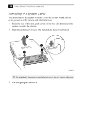
24 VAIO Slimtop™ Reference Manual Removing the System Cover You must remove the system cover to access the system board, add-in cards, power supply, battery, and internal drives. 1 From the rear of the unit, push down on a rubber mat. 3 Lift straight up to the chassis. 2 Slide the system cover back. The panel slides back about ½ inch. 3 KY0064B.VSD ✍ This works best if the spacers are installed on the unit, or the unit sits on the two tabs that secure the system cover to remove it.
24 VAIO Slimtop™ Reference Manual Removing the System Cover You must remove the system cover to access the system board, add-in cards, power supply, battery, and internal drives. 1 From the rear of the unit, push down on a rubber mat. 3 Lift straight up to the chassis. 2 Slide the system cover back. The panel slides back about ½ inch. 3 KY0064B.VSD ✍ This works best if the spacers are installed on the unit, or the unit sits on the two tabs that secure the system cover to remove it.
Reference Manual
Page 40
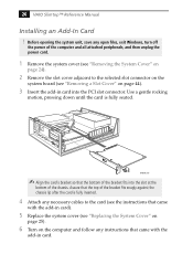
...on page 44). 3 Insert the add-in card). 5 Replace the system cover (see "Removing a Slot Cover" on the computer and follow any open files, exit Windows, turn off the power of the computer and all attached peripherals, and then unplug the power cord. 1 Remove the system cover (see "Removing the System Cover... the instructions that came with the add-in card into the slot at the bottom of the bracket fits into the PCI slot connector. 26 VAIO Slimtop™ Reference Manual Installing an Add-In Card ! Assure that the top of the bracket fits snugly against the chassis lip after the card ...
...on page 44). 3 Insert the add-in card). 5 Replace the system cover (see "Removing a Slot Cover" on the computer and follow any open files, exit Windows, turn off the power of the computer and all attached peripherals, and then unplug the power cord. 1 Remove the system cover (see "Removing the System Cover... the instructions that came with the add-in card into the slot at the bottom of the bracket fits into the PCI slot connector. 26 VAIO Slimtop™ Reference Manual Installing an Add-In Card ! Assure that the top of the bracket fits snugly against the chassis lip after the card ...
Reference Manual
Page 42
28 VAIO Slimtop™ Reference Manual 5 If you do not replace the card or install another add-in card, install a slot cover over the vacant slot at the rear of the chassis (see "Covering an Open I/O Slot" on page 45). 6 Replace the system cover (see "Replacing the System Cover" on page 25).
28 VAIO Slimtop™ Reference Manual 5 If you do not replace the card or install another add-in card, install a slot cover over the vacant slot at the rear of the chassis (see "Covering an Open I/O Slot" on page 45). 6 Replace the system cover (see "Replacing the System Cover" on page 25).
Reference Manual
Page 44
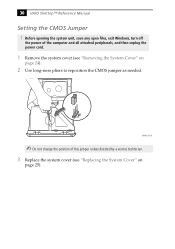
Before opening the system unit, save any open files, exit Windows, turn off the power of this jumper unless directed by a service technician. 3 Replace the system cover (see "Removing the System Cover" on page 25). MAN007.VSD ✍ Do not change the position of the computer and all attached peripherals, and then unplug the power cord. 1 Remove the system cover (see "Replacing the System Cover" on page 24). 2 Use long-nose pliers to reposition the CMOS jumper as needed. 30 VAIO Slimtop™ Reference Manual Setting the CMOS Jumper !
Before opening the system unit, save any open files, exit Windows, turn off the power of this jumper unless directed by a service technician. 3 Replace the system cover (see "Removing the System Cover" on page 25). MAN007.VSD ✍ Do not change the position of the computer and all attached peripherals, and then unplug the power cord. 1 Remove the system cover (see "Replacing the System Cover" on page 24). 2 Use long-nose pliers to reposition the CMOS jumper as needed. 30 VAIO Slimtop™ Reference Manual Setting the CMOS Jumper !


