Reference Manual
Page 2
... in part without prior written approval. SONY ELECTRONICS INC. Model Number: PCV-J100 Serial Number ii Some of their respective owners. Sony, VAIO, the VAIO logo, and i.LINK are trademarks or registered trademarks of the software may not be identical to the model and serial number when you call your VAIO® computer. Owner's Record The model number...
... in part without prior written approval. SONY ELECTRONICS INC. Model Number: PCV-J100 Serial Number ii Some of their respective owners. Sony, VAIO, the VAIO logo, and i.LINK are trademarks or registered trademarks of the software may not be identical to the model and serial number when you call your VAIO® computer. Owner's Record The model number...
Reference Manual
Page 3
...; Do not use the modem or a telephone to report a gas leak in this product will increase eye hazard. To change the backup battery, contact your desktop to rain or moisture.To avoid electrical shock, do not attempt to reduce the risk of fire, use of the leak. ❑ The socket outlet... Laser Diode Properties Laser output Wave Length 1.0mW(Read) 35mW (Write) 777-787nm ❑ To prevent fire or shock hazard, do not expose your nearest Sony Service Center. !
...; Do not use the modem or a telephone to report a gas leak in this product will increase eye hazard. To change the backup battery, contact your desktop to rain or moisture.To avoid electrical shock, do not attempt to reduce the risk of fire, use of the leak. ❑ The socket outlet... Laser Diode Properties Laser output Wave Length 1.0mW(Read) 35mW (Write) 777-787nm ❑ To prevent fire or shock hazard, do not expose your nearest Sony Service Center. !
Reference Manual
Page 5
...to radio or television reception, which the receiver is no guarantee that comply with Part 15 of Conformity Trade Name: SONY Model No.: PCV-J100 Responsible Party: Sony Electronics Inc. Operation is subject to the two following conditions: (1) This device may be shielded and grounded. If... for a Class B digital device, pursuant to radio communications. You are cautioned that are designed to operate this computer product. Address: 1 Sony Drive Park Ridge, NJ 07656 Telephone: 201-930-6970 This phone number is likely to result in a residential installation. Only...
...to radio or television reception, which the receiver is no guarantee that comply with Part 15 of Conformity Trade Name: SONY Model No.: PCV-J100 Responsible Party: Sony Electronics Inc. Operation is subject to the two following conditions: (1) This device may be shielded and grounded. If... for a Class B digital device, pursuant to radio communications. You are cautioned that are designed to operate this computer product. Address: 1 Sony Drive Park Ridge, NJ 07656 Telephone: 201-930-6970 This phone number is likely to result in a residential installation. Only...
Reference Manual
Page 6
...terminal equipment causes harm to the telephone network, the telephone company will provide advance notice in order for you , call . For the Sony Service Center nearest you to make changes in its facilities, equipment, operations or procedures that temporary discontinuance of the RENs should be used to...an incoming call 1-888-4SONYPC (1888-476-6972). FCC Part 68 This equipment complies with this modem, for any person to use a computer or other electronic device to send any message via a telephone facsimile machine unless such message clearly contains, in a margin at the top or...
...terminal equipment causes harm to the telephone network, the telephone company will provide advance notice in order for you , call . For the Sony Service Center nearest you to make changes in its facilities, equipment, operations or procedures that temporary discontinuance of the RENs should be used to...an incoming call 1-888-4SONYPC (1888-476-6972). FCC Part 68 This equipment complies with this modem, for any person to use a computer or other electronic device to send any message via a telephone facsimile machine unless such message clearly contains, in a margin at the top or...
Reference Manual
Page 7
... BATTERY You can return your unwanted lithium ion batteries to your telephone directory under 'Privacy Issues' and/or 'Terms of Service.' For the Sony Service Center nearest you, call 1-888-476-6972 in the United States or 1-800-961-7669 in this device may be prohibited. Keep ... Évacuer promptement la batterie us ées selon les directives du fabricant. ! vii Telephone Consumer Guidelines (Canada) Please refer to your nearest Sony Service Center or Factory Service Center. ✍ In some areas the disposal of lithium ion batteries in household or business trash may present a fire ...
... BATTERY You can return your unwanted lithium ion batteries to your telephone directory under 'Privacy Issues' and/or 'Terms of Service.' For the Sony Service Center nearest you, call 1-888-476-6972 in the United States or 1-800-961-7669 in this device may be prohibited. Keep ... Évacuer promptement la batterie us ées selon les directives du fabricant. ! vii Telephone Consumer Guidelines (Canada) Please refer to your nearest Sony Service Center or Factory Service Center. ✍ In some areas the disposal of lithium ion batteries in household or business trash may present a fire ...
Reference Manual
Page 8
Before installing this equipment, users should ensure that the user disconnect the equipment. NOTICE: The Ringer Equivalence Number (REN) assigned to request that it is 0.7. The Ringer Equivalence Number for their own protection that compliance with the above conditions may give the telecommunications company cause to each terminal device provides an indication of the maximum number of connection. Les réparations de matériel homologué doivent être coordonnées par un représentant désigné par le fournisseur. The Department does not ...
Before installing this equipment, users should ensure that the user disconnect the equipment. NOTICE: The Ringer Equivalence Number (REN) assigned to request that it is 0.7. The Ringer Equivalence Number for their own protection that compliance with the above conditions may give the telecommunications company cause to each terminal device provides an indication of the maximum number of connection. Les réparations de matériel homologué doivent être coordonnées par un représentant désigné par le fournisseur. The Department does not ...
Reference Manual
Page 11
vi Telephone Consumer Guidelines (Canada vii DISPOSAL OF LITHIUM ION BATTERY vii INDUSTRY CANADA NOTICE viii AVIS DE L'INDUSTRIE CANADA viii Chapter 1 - Configuring Your System Accessing the BIOS Setup Utility 16 Changing the Display's Power Management Settings 17 Configuring the System Board 19 xi Contents Notice to Users ii Safety Information and Caution iii Regulatory Information v FCC Part 68 vi Telephone Consumer Protection Act of 1991 (United States) ..... Identifying Components Front View 2 Drives 3 Buttons and Switches 4 Indicators 5 Rear View ...6 Icons ...7 I/O ...
vi Telephone Consumer Guidelines (Canada vii DISPOSAL OF LITHIUM ION BATTERY vii INDUSTRY CANADA NOTICE viii AVIS DE L'INDUSTRIE CANADA viii Chapter 1 - Configuring Your System Accessing the BIOS Setup Utility 16 Changing the Display's Power Management Settings 17 Configuring the System Board 19 xi Contents Notice to Users ii Safety Information and Caution iii Regulatory Information v FCC Part 68 vi Telephone Consumer Protection Act of 1991 (United States) ..... Identifying Components Front View 2 Drives 3 Buttons and Switches 4 Indicators 5 Rear View ...6 Icons ...7 I/O ...
Reference Manual
Page 12
... System Memory 32 Removing a Memory Module 36 Removing a Slot Cover 38 Covering an Open I/O Slot 39 Installing a 3½" Internal Hard Disk Drive 40 Chapter 4 - xii VAIO® Reference Manual Chapter 3 -
... System Memory 32 Removing a Memory Module 36 Removing a Slot Cover 38 Covering an Open I/O Slot 39 Installing a 3½" Internal Hard Disk Drive 40 Chapter 4 - xii VAIO® Reference Manual Chapter 3 -
Reference Manual
Page 13
Miscellaneous Technical Information About User and Supervisor Passwords 84 Beep Code Error Messages 85 PCI Configuration Status and Error Messages 86 DMA Channel Assignments 87 System I /O and Expansion Slots 95 Drives and Controllers 96 System BIOS 96 Specifications Processor 93 Chipset ...93 PCI Bus ...93 Memory Modules (DIMMs 93 DIMM Configurations 94 L2 Cache ...94 Graphics ...94 Audio ...95 Communications 95 I /O Address Map 88 Memory Map 90 IRQ Settings 91 Chapter 10 - xiii Chapter 8 - CMOS Setup Options Main Screen 71 Advanced Screen 73 Power Screen 79 Boot Screen 81...
Miscellaneous Technical Information About User and Supervisor Passwords 84 Beep Code Error Messages 85 PCI Configuration Status and Error Messages 86 DMA Channel Assignments 87 System I /O and Expansion Slots 95 Drives and Controllers 96 System BIOS 96 Specifications Processor 93 Chipset ...93 PCI Bus ...93 Memory Modules (DIMMs 93 DIMM Configurations 94 L2 Cache ...94 Graphics ...94 Audio ...95 Communications 95 I /O Address Map 88 Memory Map 90 IRQ Settings 91 Chapter 10 - xiii Chapter 8 - CMOS Setup Options Main Screen 71 Advanced Screen 73 Power Screen 79 Boot Screen 81...
Reference Manual
Page 15
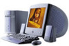
Internal components are identified in the appropriate section of the VAIO® Computer. Chapter 1 Identifying Components The following sections identify and describe each component that is visible from the exterior of this manual. 1
Internal components are identified in the appropriate section of the VAIO® Computer. Chapter 1 Identifying Components The following sections identify and describe each component that is visible from the exterior of this manual. 1
Reference Manual
Page 17
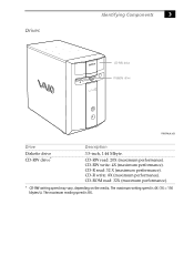
CD-RW write: 4X (maximum performance). CD-ROM read : 32 X (maximum performance). The maximum writing speed is 8X. Drives Identifying Components 3 CD-RW drive Diskette drive FRNTPNLA.VSD Drive Diskette drive CD-RW drive* Description 3.5-inch, 1.44 Mbyte. CD-R read : 32X (maximum performance). * CD-RW writing speed may vary, depending on the media. CD-R write: 8X (maximum performance). The maximum reading speed is 4X (1X = 150 kbytes/s). CD-RW read: 20X (maximum performance).
CD-RW write: 4X (maximum performance). CD-ROM read : 32 X (maximum performance). The maximum writing speed is 8X. Drives Identifying Components 3 CD-RW drive Diskette drive FRNTPNLA.VSD Drive Diskette drive CD-RW drive* Description 3.5-inch, 1.44 Mbyte. CD-R read : 32X (maximum performance). * CD-RW writing speed may vary, depending on the media. CD-R write: 8X (maximum performance). The maximum reading speed is 4X (1X = 150 kbytes/s). CD-RW read: 20X (maximum performance).
Reference Manual
Page 18
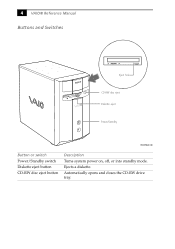
Automatically opens and closes the CD-RW drive tray. 4 VAIO® Reference Manual Buttons and Switches Eject hole CD-RW disc eject Diskette eject Power/Standby FRNTPNLB.VSD Button or switch Power/Standby switch Diskette eject button CD-RW disc eject button Description Turns system power on, off, or into standby mode. Ejects a diskette.
Automatically opens and closes the CD-RW drive tray. 4 VAIO® Reference Manual Buttons and Switches Eject hole CD-RW disc eject Diskette eject Power/Standby FRNTPNLB.VSD Button or switch Power/Standby switch Diskette eject button CD-RW disc eject button Description Turns system power on, off, or into standby mode. Ejects a diskette.
Reference Manual
Page 19
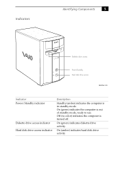
On (green) indicates diskette drive activity. On (amber) indicates hard disk drive activity. On (green) indicates the computer is in standby mode. Indicators Identifying Components 5 Diskette drive access Power/Standby Hard disk drive access FRNTPNLC.VSD Indicator Power/Standby indicator Diskette drive access indicator Hard disk drive access indicator Description Standby (amber) indicates the computer is out of standby mode, ready to use. Off (no color) indicates the computer is turned off.
On (green) indicates diskette drive activity. On (amber) indicates hard disk drive activity. On (green) indicates the computer is in standby mode. Indicators Identifying Components 5 Diskette drive access Power/Standby Hard disk drive access FRNTPNLC.VSD Indicator Power/Standby indicator Diskette drive access indicator Hard disk drive access indicator Description Standby (amber) indicates the computer is out of standby mode, ready to use. Off (no color) indicates the computer is turned off.
Reference Manual
Page 21
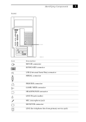
Icons Identifying Components 7 Icon labels Icon OM04692X.VSD Description MOUSE connector KEYBOARD connector USB (Universal Serial Bus) connector SERIAL connector PRINTER connector GAME/MIDI connector HEADPHONES connector LINE IN jack (audio) MIC (microphone) jack MONITOR connector LINE (for telephone line from primary service jack)
Icons Identifying Components 7 Icon labels Icon OM04692X.VSD Description MOUSE connector KEYBOARD connector USB (Universal Serial Bus) connector SERIAL connector PRINTER connector GAME/MIDI connector HEADPHONES connector LINE IN jack (audio) MIC (microphone) jack MONITOR connector LINE (for telephone line from primary service jack)
Reference Manual
Page 22
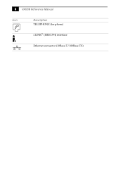
8 VAIO® Reference Manual Icon Description TELEPHONE (for phone) i.LINK® (IEEE1394) interface Ethernet connector (10Base-T/100Base-TX)
8 VAIO® Reference Manual Icon Description TELEPHONE (for phone) i.LINK® (IEEE1394) interface Ethernet connector (10Base-T/100Base-TX)
Reference Manual
Page 23
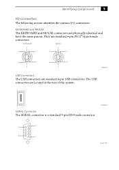
Identifying Components 9 I/O Connectors The following section identifies the various I/O connectors. KEYBOARD and MOUSE The KEYBOARD and MOUSE connectors are standard 6-pin PS/2®-type female connectors. SERIAL Connector The SERIAL connector is a standard 9-pin DB-9 male connector. They are physically identical and have the same pinout. The USB connectors are standard 4-pin USB connectors. KEYBOARD MOUSE 2 2 3 1 3 1 4 6 5 4 6 5 KY0002.VS USB Connectors The USB connectors are located at the rear of the system. KY0003.VS 5 9 6 1 KY0057.VSD
Identifying Components 9 I/O Connectors The following section identifies the various I/O connectors. KEYBOARD and MOUSE The KEYBOARD and MOUSE connectors are standard 6-pin PS/2®-type female connectors. SERIAL Connector The SERIAL connector is a standard 9-pin DB-9 male connector. They are physically identical and have the same pinout. The USB connectors are standard 4-pin USB connectors. KEYBOARD MOUSE 2 2 3 1 3 1 4 6 5 4 6 5 KY0002.VS USB Connectors The USB connectors are located at the rear of the system. KY0003.VS 5 9 6 1 KY0057.VSD

Reference Manual
Page 24
10 VAIO® Reference Manual PRINTER Connector The PRINTER connector is a standard 25-pin DB-25 female connector. 13 25 14 1 KY0005.VSD MONITOR The MONITOR connector is a standard 15-pin female high-density VGAtype connector. 10 15 5 11 1 6 KY0004.VSD
10 VAIO® Reference Manual PRINTER Connector The PRINTER connector is a standard 25-pin DB-25 female connector. 13 25 14 1 KY0005.VSD MONITOR The MONITOR connector is a standard 15-pin female high-density VGAtype connector. 10 15 5 11 1 6 KY0004.VSD
Reference Manual
Page 25
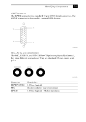
Identifying Components 11 GAME Connector The GAME connector is also used to connect MIDI devices. 8 15 9 1 KY0012.VSD MIC, LINE IN, and HEADPHONES The MIC, LINE IN, and HEADPHONES jacks are standard 3.5 mm stereo minijacks. Electret condenser microphone input. 1.0 Vrms (typical), 10 Kohm impedance. HEADPHONES LINE IN MIC Connector HEADPHONES MIC LINE IN Description 1.0 Vrms (typical). KY0013.VSD The GAME connector is a standard 15-pin DB-15 female connector. They are physically identical, but have different connections.
Identifying Components 11 GAME Connector The GAME connector is also used to connect MIDI devices. 8 15 9 1 KY0012.VSD MIC, LINE IN, and HEADPHONES The MIC, LINE IN, and HEADPHONES jacks are standard 3.5 mm stereo minijacks. Electret condenser microphone input. 1.0 Vrms (typical), 10 Kohm impedance. HEADPHONES LINE IN MIC Connector HEADPHONES MIC LINE IN Description 1.0 Vrms (typical). KY0013.VSD The GAME connector is a standard 15-pin DB-15 female connector. They are physically identical, but have different connections.
Reference Manual
Page 26
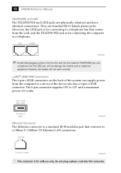
However, the modem will not damage the modem card or telephone equipment. This connector is for connecting the computer to 12V and a maximum power of 6 watts. 6-pin i.LINK (IEEE-1394) On back of system KY0100.VSD ! Do not plug a phone cord into ...supply power from the wall into the modem's TELEPHONE jack, and a telephone into this connector. They are physically identical and have identical connections. 12 VAIO® Reference Manual TELEPHONE and LINE The TELEPHONE and LINE jacks are standard RJ-11 female phone jacks. LINE PHONE KY0014.VSD ✍ Accidentally plugging...
However, the modem will not damage the modem card or telephone equipment. This connector is for connecting the computer to 12V and a maximum power of 6 watts. 6-pin i.LINK (IEEE-1394) On back of system KY0100.VSD ! Do not plug a phone cord into ...supply power from the wall into the modem's TELEPHONE jack, and a telephone into this connector. They are physically identical and have identical connections. 12 VAIO® Reference Manual TELEPHONE and LINE The TELEPHONE and LINE jacks are standard RJ-11 female phone jacks. LINE PHONE KY0014.VSD ✍ Accidentally plugging...
Reference Manual
Page 27
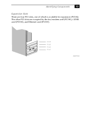
Identifying Components 13 Expansion Slots There are occupied by the fax/modem card (PCI #1), i.LINK card (PCI #2), and Ethernet card (PCI #3). PCI #4 PCI #3 PCI #2 PCI #1 OM04577B.VSD The other PCI slots are four PCI slots, one of which is available for expansion (PCI #4).
Identifying Components 13 Expansion Slots There are occupied by the fax/modem card (PCI #1), i.LINK card (PCI #2), and Ethernet card (PCI #3). PCI #4 PCI #3 PCI #2 PCI #1 OM04577B.VSD The other PCI slots are four PCI slots, one of which is available for expansion (PCI #4).