Integration Guide
Page 3
... Status Menu 3-13 3-4-1. System Log 3-23 3-6-3. Call Log 3-26 3-7. Turning Off the System 2-1 2-2. Operation Log 3-25 3-6-4. Microphone Connection 1-10 1-1-4. System Connection via a LAN and a SIP 1-26 1-2-2. Layout Information for Input 1-41 1-3. PCS-XG Series Models Connection Using SIP... 1-27 1-2-3. To Connect a Video Equipment for PCS-XG Series Models 1-3 1-1-1. Test Procedure 3-27 3-7-2. Maintenance 1-1. Turning On the System 2-1 2-1-2. Monitor Connection 1-20 1-1-7. Firmware Update by Using WEB Control 3-2 3-1-2. Replacing...
... Status Menu 3-13 3-4-1. System Log 3-23 3-6-3. Call Log 3-26 3-7. Turning Off the System 2-1 2-2. Operation Log 3-25 3-6-4. Microphone Connection 1-10 1-1-4. System Connection via a LAN and a SIP 1-26 1-2-2. Layout Information for Input 1-41 1-3. PCS-XG Series Models Connection Using SIP... 1-27 1-2-3. To Connect a Video Equipment for PCS-XG Series Models 1-3 1-1-1. Test Procedure 3-27 3-7-2. Maintenance 1-1. Turning On the System 2-1 2-1-2. Monitor Connection 1-20 1-1-7. Firmware Update by Using WEB Control 3-2 3-1-2. Replacing...
Integration Guide
Page 5
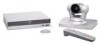
... both PCS-XG55 and PCS-XG55S. Position the camera and microphone appropriately in Section 1-3. The difference between PCS-XG80/XG80S and PCS-XG55/XG55S is , PCS-XG80, PCS-XG80S, PCS-XG55 and PCS-XG55S. This system integration manual defines and uses words as below. (See below Fig.) "PCS-XG Series models" means the four models, that is described in the video conferencing room. PCS-XG80...
... both PCS-XG55 and PCS-XG55S. Position the camera and microphone appropriately in Section 1-3. The difference between PCS-XG80/XG80S and PCS-XG55/XG55S is , PCS-XG80, PCS-XG80S, PCS-XG55 and PCS-XG55S. This system integration manual defines and uses words as below. (See below Fig.) "PCS-XG Series models" means the four models, that is described in the video conferencing room. PCS-XG80...
Integration Guide
Page 11
...2nd camera is supported only by Ver. 2.0 and later.) Camera image flip Allows you should not set the "RF Remote Control Reception" to "Camera". The 1 connector on the PCS-XG80 main unit corresponds to EVI-HD1 Shell * The S VIDEO ...done from the setting menu. Supported cameras The PCS-XG Series main unit can be connected to the operating instructions supplied with the PCS-XG Series models. n When using a camera other camera models. This function is installed in a ceiling. This is separately required. (For detail, contact your local Sony Sales Office/Service Center.) Breakout ...
...2nd camera is supported only by Ver. 2.0 and later.) Camera image flip Allows you should not set the "RF Remote Control Reception" to "Camera". The 1 connector on the PCS-XG80 main unit corresponds to EVI-HD1 Shell * The S VIDEO ...done from the setting menu. Supported cameras The PCS-XG Series main unit can be connected to the operating instructions supplied with the PCS-XG Series models. n When using a camera other camera models. This function is installed in a ceiling. This is separately required. (For detail, contact your local Sony Sales Office/Service Center.) Breakout ...

Integration Guide
Page 13
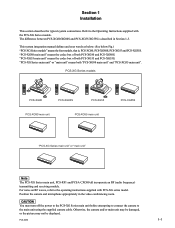
Connecting HD camera as 2nd camera Connecting HD camera as 2nd Camera is supported since Ver. 2.0 release) D-sub 15 pin VIDEO IN Y Pb Pr AUDIO 2 IN L R VIDEO (Y, Pb, Pr) IN OPEN MAINTENANCE Component cable * Commercially available Registration of the PCS-XG Series main unit. Connecting PCSA-CG70 as 1st camera When using a camera other than PCSA-CXG80, you should not set the "RF Remote Control Reception...
Connecting HD camera as 2nd camera Connecting HD camera as 2nd Camera is supported since Ver. 2.0 release) D-sub 15 pin VIDEO IN Y Pb Pr AUDIO 2 IN L R VIDEO (Y, Pb, Pr) IN OPEN MAINTENANCE Component cable * Commercially available Registration of the PCS-XG Series main unit. Connecting PCSA-CG70 as 1st camera When using a camera other than PCSA-CXG80, you should not set the "RF Remote Control Reception...
Integration Guide
Page 18
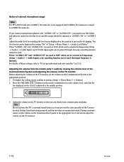
...need to use Mic Mixer and adjust its setting. (Setup → Home Menu 3 → Volume) 2. When "AUDIO 1 IN" and "AUDIO 2 IN" are used . The level meter can clearly hear a remote party speaking. Notice of "Setup → Home Menu 3 → Audio Level Meter". Adjust ...PCS-XG80 If you connect external microphones with "AUDIO 1 IN" or "AUDIO 2 IN", you can be used as it may prevent the echo canceller of the Communication System and adjusting the volume on the TV monitor Before adjusting the volume on the Communication System to prevent level clipping. For details of Menu settings...
...need to use Mic Mixer and adjust its setting. (Setup → Home Menu 3 → Volume) 2. When "AUDIO 1 IN" and "AUDIO 2 IN" are used . The level meter can clearly hear a remote party speaking. Notice of "Setup → Home Menu 3 → Audio Level Meter". Adjust ...PCS-XG80 If you connect external microphones with "AUDIO 1 IN" or "AUDIO 2 IN", you can be used as it may prevent the echo canceller of the Communication System and adjusting the volume on the TV monitor Before adjusting the volume on the Communication System to prevent level clipping. For details of Menu settings...
Integration Guide
Page 25
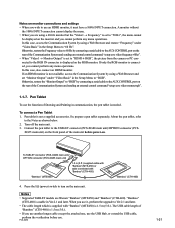
..., access the Communication System by connecting a serial cable to "RGB" by using a Web Browser and restore "Frequency" under "Video:Basic" in communication, the pen tablet is needed. To connect a Pen Tablet 1. Pen tablet is usable in the Setup Menu to turn on monitor connections and settings . To TABLET connector (PCS-XG80 main unit)/ OPTION connector (PCS-XG55 main unit) 1.5 m (5 ft...
..., access the Communication System by connecting a serial cable to "RGB" by using a Web Browser and restore "Frequency" under "Video:Basic" in communication, the pen tablet is needed. To connect a Pen Tablet 1. Pen tablet is usable in the Setup Menu to turn on monitor connections and settings . To TABLET connector (PCS-XG80 main unit)/ OPTION connector (PCS-XG55 main unit) 1.5 m (5 ft...

Integration Guide
Page 27
... setup menu, set "RF Remote Control Reception" to be erased even when the batteries in 2-2-2 3. To cancel pairing, press the I /O button [ENTER] button [TOOLS] button PCS-XG80 1-23 Press the [ENTER] button on the Remote Com- form the pairing before the installation. In this case, press the [ENTER] button on the main unit. 2. mander are replaced. . When the camera...
... setup menu, set "RF Remote Control Reception" to be erased even when the batteries in 2-2-2 3. To cancel pairing, press the I /O button [ENTER] button [TOOLS] button PCS-XG80 1-23 Press the [ENTER] button on the Remote Com- form the pairing before the installation. In this case, press the [ENTER] button on the main unit. 2. mander are replaced. . When the camera...

Integration Guide
Page 34
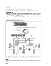
.../STANDBY / / / T W POWER/STANDBY / POWER/STANDBY / 4 POWER/STANDBY / POWER/STANDBY / 1 PCS-XG80S HD Visual POWER/STANDBY Communication System / POWER/STANDBY / 2 PCSA-CXG80 HD Camera Unit 3 PCS-RF1 Remote Commander 4 TV monitor (not supplied) 5 PCS-A1 microphone 6 HD MCU software PCSA-MCG80 (Option) 1-30 PCS-XG80 AMX Device Discovery . Multipoint Connection (Example of the system are restricted as follows when using...
.../STANDBY / / / T W POWER/STANDBY / POWER/STANDBY / 4 POWER/STANDBY / POWER/STANDBY / 1 PCS-XG80S HD Visual POWER/STANDBY Communication System / POWER/STANDBY / 2 PCSA-CXG80 HD Camera Unit 3 PCS-RF1 Remote Commander 4 TV monitor (not supplied) 5 PCS-A1 microphone 6 HD MCU software PCSA-MCG80 (Option) 1-30 PCS-XG80 AMX Device Discovery . Multipoint Connection (Example of the system are restricted as follows when using...

Integration Guide
Page 52
..., PinP/PandP/Side by Side displays, 720PYPbPr input and S-video input and RGB input are PCSXG Series models unique settings. When 1080i mode is available only for connection via LAN. These are explained as below. 1080i Mode (PCS-XG80/XG80S only) Transmission and reception of the picture in Initial Setup Wizard, but these settings are not available.
..., PinP/PandP/Side by Side displays, 720PYPbPr input and S-video input and RGB input are PCSXG Series models unique settings. When 1080i mode is available only for connection via LAN. These are explained as below. 1080i Mode (PCS-XG80/XG80S only) Transmission and reception of the picture in Initial Setup Wizard, but these settings are not available.
Integration Guide
Page 53
...When audio input is "On". PCS-XG80 2-7 The echo canceller will be enabled, when "Echo Canceller" setting is used as AUX and (even if "Echo Canceller" setting is adjusted to the line level through a microphone mixer to the AUDIO 1 IN or AUDIO 2 IN input connectors, set "Setup → Audio 1 → ...input level will be the line level. When "Audio Input" is enabled. To set "Echo Canceller" field. Menu setting is not enabled. In this column has no effect, regardless of whether "Echo canceller" is set to "AUX" The setting made in this case, the echo canceller is...
...When audio input is "On". PCS-XG80 2-7 The echo canceller will be enabled, when "Echo Canceller" setting is used as AUX and (even if "Echo Canceller" setting is adjusted to the line level through a microphone mixer to the AUDIO 1 IN or AUDIO 2 IN input connectors, set "Setup → Audio 1 → ...input level will be the line level. When "Audio Input" is enabled. To set "Echo Canceller" field. Menu setting is not enabled. In this column has no effect, regardless of whether "Echo canceller" is set to "AUX" The setting made in this case, the echo canceller is...

Integration Guide
Page 58
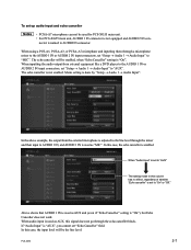
... (Figure 1). Important Information About Installation and Setting of Connection Using IP Line of Two Networks (PCS-XG80/XG80S only) Important information regarding installation/settings When using the dual network feature, install and set the Remote Access Password in the Administrator Setup menu (Figure 2). (The telnet, SSH or Web access to "Disabled" Fig. 3 2-12 PCS-XG80 Also, at the same time, set up for the global...
... (Figure 1). Important Information About Installation and Setting of Connection Using IP Line of Two Networks (PCS-XG80/XG80S only) Important information regarding installation/settings When using the dual network feature, install and set the Remote Access Password in the Administrator Setup menu (Figure 2). (The telnet, SSH or Web access to "Disabled" Fig. 3 2-12 PCS-XG80 Also, at the same time, set up for the global...

Integration Guide
Page 59
Change to "Off" Change to "Off" (Initial setting: On). . Set "Auto Answer" to "On" Fig. 4 PCS-XG80 2-13 Set "Reject Answer" to prevent unwanted connections from the global network side during a meeting (Figure 4). . The settings described below are recommended for the Answer Setup menu in order to "On" (Initial setting: Off) .*1 *1: Available only when the HD MCU software PCSA-MCG80 (available separately) is installed.
Change to "Off" Change to "Off" (Initial setting: On). . Set "Auto Answer" to "On" Fig. 4 PCS-XG80 2-13 Set "Reject Answer" to prevent unwanted connections from the global network side during a meeting (Figure 4). . The settings described below are recommended for the Answer Setup menu in order to "On" (Initial setting: Off) .*1 *1: Available only when the HD MCU software PCSA-MCG80 (available separately) is installed.
Integration Guide
Page 62
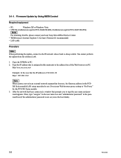
... to PC. 2. Firmware Update by Using WEB Control Required equipment . Copy the UPD file to type the user name and password appears. 3-1-1. WEB browser: Internet Explorer 5.0 or later (Version 6.0 recommended) . LAN cable Procedure n When performing the update, connect to "No Proxy" for PCS-XG55/XG55S) n For obtaining this main unit in the PCSXG Series models LAN setup must also be set. Type...
... to PC. 2. Firmware Update by Using WEB Control Required equipment . Copy the UPD file to type the user name and password appears. 3-1-1. WEB browser: Internet Explorer 5.0 or later (Version 6.0 recommended) . LAN cable Procedure n When performing the update, connect to "No Proxy" for PCS-XG55/XG55S) n For obtaining this main unit in the PCSXG Series models LAN setup must also be set. Type...

Integration Guide
Page 74
...: Displays the terminal name of a remote party. 2 Remote Address: Displays the address of motion pictures. n The audio encoding and video encoding formats used . Displays whether the unit is ready to select "Communication Mode Status", and then press the [ENTER] button. Use the button on the remote site. 5 Frame Rate: 6 Rate: 7 Line I/F: 8 Camera Control: 9 H239: Displays the maximum...
...: Displays the terminal name of a remote party. 2 Remote Address: Displays the address of motion pictures. n The audio encoding and video encoding formats used . Displays whether the unit is ready to select "Communication Mode Status", and then press the [ENTER] button. Use the button on the remote site. 5 Frame Rate: 6 Rate: 7 Line I/F: 8 Camera Control: 9 H239: Displays the maximum...

Integration Guide
Page 81
... the HDMI monitor being used for O some connections. Input 720p60 signal from GUI. Welsh language (V.2 supports welsh in letter box format, O when sending video such as the one before connection. Menu translucent change (nn = 01 - 99, O default 86) n This service command has priority over standard setup from rear RGB connec- To adjust video quality on the HDMI monitor when "Monitor...
... the HDMI monitor being used for O some connections. Input 720p60 signal from GUI. Welsh language (V.2 supports welsh in letter box format, O when sending video such as the one before connection. Menu translucent change (nn = 01 - 99, O default 86) n This service command has priority over standard setup from rear RGB connec- To adjust video quality on the HDMI monitor when "Monitor...

Integration Guide
Page 84
...Download of the main unit cannot be collected. 3-24 PCS-XG80 Open the web page and then select "Download" in "3-1-1. Then, click "Download" to steps 2 and 3 in the left column. During operation, the system log is connected to the MAINTENANCE connector on the software terminal connected... settings for the software terminal (Hyper Terminal, for example) on a PC which is displayed on the main unit by Using WEB Control", or refer to the figure below. Firmware Update by a serial crossover cable, refer to the operating instructions supplied with the PCS-XG Series models....
...Download of the main unit cannot be collected. 3-24 PCS-XG80 Open the web page and then select "Download" in "3-1-1. Then, click "Download" to steps 2 and 3 in the left column. During operation, the system log is connected to the MAINTENANCE connector on the software terminal connected... settings for the software terminal (Hyper Terminal, for example) on a PC which is displayed on the main unit by Using WEB Control", or refer to the figure below. Firmware Update by a serial crossover cable, refer to the operating instructions supplied with the PCS-XG Series models....

Integration Guide
Page 85
...Service Menu". Using "Save Operation Log" of operation made by remote commander, external command, and cgi command (Web interface). Firmware Update by Using WEB Control", or refer to "3-5. PCS-XG80 3-25 Description on the front panel of "Save Operation Log". Open the web page and then select "Download"...Before starting up the web interface, refer to the Memory Stick as the login name and password. Getting the Operation Log via the Web Interface Before starting the Service Menu, refer to the operating instructions supplied with the PCS-XG Series models. The example of ...
...Service Menu". Using "Save Operation Log" of operation made by remote commander, external command, and cgi command (Web interface). Firmware Update by Using WEB Control", or refer to "3-5. PCS-XG80 3-25 Description on the front panel of "Save Operation Log". Open the web page and then select "Download"...Before starting up the web interface, refer to the Memory Stick as the login name and password. Getting the Operation Log via the Web Interface Before starting the Service Menu, refer to the operating instructions supplied with the PCS-XG Series models. The example of ...

Integration Guide
Page 86
..., refer to steps 2 and 3 in "3-1-1. Getting the System Log via the Service Menu Insert the Memory Stick on which the call log is as shown below . Firmware Update by Using WEB Control", or refer to "3-5. Call Log start_date_str end_date_str duration 06-02-2008 09:56:09 6-02-2008 ..." of the main unit. Download of "Save Call Log". 3-6-4. Description on the front panel of "Save/Load" in the left column. Getting the Call Log via the Web Interface Before starting the Service Menu, refer to the operating instructions supplied with the PCS-XG Series models. The example of Call Log...
..., refer to steps 2 and 3 in "3-1-1. Getting the System Log via the Service Menu Insert the Memory Stick on which the call log is as shown below . Firmware Update by Using WEB Control", or refer to "3-5. Call Log start_date_str end_date_str duration 06-02-2008 09:56:09 6-02-2008 ..." of the main unit. Download of "Save Call Log". 3-6-4. Description on the front panel of "Save/Load" in the left column. Getting the Call Log via the Web Interface Before starting the Service Menu, refer to the operating instructions supplied with the PCS-XG Series models. The example of Call Log...

Integration Guide
Page 88
...from the 1162 packet losses are given below . Get a system log. (Refer to Step 2. When no problem in the Setup Menu, as shown below. Save the log for the "pkt:disorder/loss/rcvr/ rcv:" line using the recording ...Error Correction (FEC): Off Packet Resend Request (ARQ): On Adaptive Rate Control (ARC): Off Auto Bandwidth Detection: Off 2. PCS-XG Series models LAN Setup menu setting Make the "QoS1" and "QoS2" setting in the network or PCS-XG Series main unit. After the recording of how to read the log are recovered by Hyper Terminal or other terminal software...
...from the 1162 packet losses are given below . Get a system log. (Refer to Step 2. When no problem in the Setup Menu, as shown below. Save the log for the "pkt:disorder/loss/rcvr/ rcv:" line using the recording ...Error Correction (FEC): Off Packet Resend Request (ARQ): On Adaptive Rate Control (ARC): Off Auto Bandwidth Detection: Off 2. PCS-XG Series models LAN Setup menu setting Make the "QoS1" and "QoS2" setting in the network or PCS-XG Series main unit. After the recording of how to read the log are recovered by Hyper Terminal or other terminal software...

Integration Guide
Page 89
...PC to the manual supplied with the mirroring switch for details on PC for packet capture. Step 2: Capturing Network Packets Capture network packets by using packet capturing software that helps you to determine where the packet losses occur. Preparations: Connect a mirroring switch between the switch and the PCS...has occurred by inserting the Mirroring Switch. Wireshark Download Site: http://www.wireshark.org/ 2. If there are detected in the capture log. The checking procedure is connected to Step 4. Install capture software (e.g. If the symptom of the Mirroring Switch ...
...PC to the manual supplied with the mirroring switch for details on PC for packet capture. Step 2: Capturing Network Packets Capture network packets by using packet capturing software that helps you to determine where the packet losses occur. Preparations: Connect a mirroring switch between the switch and the PCS...has occurred by inserting the Mirroring Switch. Wireshark Download Site: http://www.wireshark.org/ 2. If there are detected in the capture log. The checking procedure is connected to Step 4. Install capture software (e.g. If the symptom of the Mirroring Switch ...


