Operating Instructions
Page 95
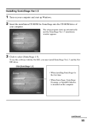
Installing SonicStage Ver.1.5 1 Turn on your computer. Click [SonicStage 1.5] • When installing SonicStage for SonicStage into the CD-ROM drive of your computer and start up automatically and the SonicStage Ver.1.5 installation window appears. 3 Click to select [SonicStage 1.5]. The setup program starts up Windows. 2 Insert the installation CD-ROM for the first time • When SonicStage, SonicStage Premium, or OpenMG Jukebox is installed on the computer continued 95 To use this software with the Net MD, you must install SonicStage Ver.1.5 and the Net MD driver.
Installing SonicStage Ver.1.5 1 Turn on your computer. Click [SonicStage 1.5] • When installing SonicStage for SonicStage into the CD-ROM drive of your computer and start up automatically and the SonicStage Ver.1.5 installation window appears. 3 Click to select [SonicStage 1.5]. The setup program starts up Windows. 2 Insert the installation CD-ROM for the first time • When SonicStage, SonicStage Premium, or OpenMG Jukebox is installed on the computer continued 95 To use this software with the Net MD, you must install SonicStage Ver.1.5 and the Net MD driver.
Operating Instructions
Page 116
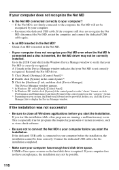
... installation, the installation cannot be possible. 116 If the Net MD is connected to your computer. - Reconnect the dedicated USB cable. Reinstall the Net MD driver. 1 Click [Start]-[Settings]-[Control Panel].1) 2 Double click [System] in the Net MD? In this case, click the [Device Manager] tab to close all Windows applications... recognize the Net MD • Is the Net MD connected correctly to your computer before you start the installation. This is inserted, the Net MD driver may occur.
... installation, the installation cannot be possible. 116 If the Net MD is connected to your computer. - Reconnect the dedicated USB cable. Reinstall the Net MD driver. 1 Click [Start]-[Settings]-[Control Panel].1) 2 Double click [System] in the Net MD? In this case, click the [Device Manager] tab to close all Windows applications... recognize the Net MD • Is the Net MD connected correctly to your computer before you start the installation. This is inserted, the Net MD driver may occur.
Operating Instructions
Page 125
N Name a disc 44 groups 55 Net MtrDac8k9s ,4941, 118 Net MD driver 116 No sound 89 O Online help 106 OpenMG 122 OpenMG Jukebox software 94, 110 P Play mode groups 52 Playlitsrtac1k0s23, 6122 Presetting radio stations automatic 71 ...
N Name a disc 44 groups 55 Net MtrDac8k9s ,4941, 118 Net MD driver 116 No sound 89 O Online help 106 OpenMG 122 OpenMG Jukebox software 94, 110 P Play mode groups 52 Playlitsrtac1k0s23, 6122 Presetting radio stations automatic 71 ...
Simple Burner V1.0 Install Instructions
Page 2
... Edition/Windows Me users 1 Click [Start]-[Settings]-[Control Panel] to "Installation" in "Installing Net MD Simple Burner", and click [Install Net MD Driver only] in system suspend/hibernation mode, data may not wake up . Refer to the operating instructions of "Computer administrator" or not, go to ...) of the Net MD Simple Burner software Click [Net MD Simple Burner] icon, and then click [About Net MD Simple Burner]. Reinstall the Net MD driver. 1 Click [Start], point to [Settings], and then click [Control Panel].* * If you are using Windows XP, click [Start], and then [Control Panel...
... Edition/Windows Me users 1 Click [Start]-[Settings]-[Control Panel] to "Installation" in "Installing Net MD Simple Burner", and click [Install Net MD Driver only] in system suspend/hibernation mode, data may not wake up . Refer to the operating instructions of "Computer administrator" or not, go to ...) of the Net MD Simple Burner software Click [Net MD Simple Burner] icon, and then click [About Net MD Simple Burner]. Reinstall the Net MD driver. 1 Click [Start], point to [Settings], and then click [Control Panel].* * If you are using Windows XP, click [Start], and then [Control Panel...
Service Manual
Page 28
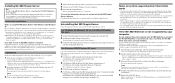
MZ-NF810/NF810CK Rewriting the Patch Data at Replacement of the microcomputer version, see "SECTION 4 TEST MODE" (page 13). • Preparation 1. Rewriting the patch data using the application, ... ) 2. Check the microcomputer version in the Normal mode. Personal computer in the personal computer. 3. Caution: The application that the Net MD Driver has been installed in which the Net MD Driver has been installed. (For further information, see "SECTION 4 TEST MODE" (page 13).) 2. Check that meets the microcomputer version in this set...
MZ-NF810/NF810CK Rewriting the Patch Data at Replacement of the microcomputer version, see "SECTION 4 TEST MODE" (page 13). • Preparation 1. Rewriting the patch data using the application, ... ) 2. Check the microcomputer version in the Normal mode. Personal computer in the personal computer. 3. Caution: The application that the Net MD Driver has been installed in which the Net MD Driver has been installed. (For further information, see "SECTION 4 TEST MODE" (page 13).) 2. Check that meets the microcomputer version in this set...
Service Manual
Page 32
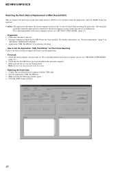
...2. For a checking method of the microcomputer version, see "SECTION 4 TEST MODE" (page 13). • Preparation 1. Check that the Net MD Driver has been installed in the Normal mode. USB cable (attached to malfunction. Start the application "NVWriter". 3. Application "NVWriter" for NV values rewriting &#...the set to the set . (For a checking method of the microcomputer version, see "SECTION 4 TEST MODE" (page 13).) 2. MZ-NF810/NF810CK Rewriting the NV values Caution: The application that meets the microcomputer version in the Test mode. • Rewriting the NV values 1.
...2. For a checking method of the microcomputer version, see "SECTION 4 TEST MODE" (page 13). • Preparation 1. Check that the Net MD Driver has been installed in the Normal mode. USB cable (attached to malfunction. Start the application "NVWriter". 3. Application "NVWriter" for NV values rewriting &#...the set to the set . (For a checking method of the microcomputer version, see "SECTION 4 TEST MODE" (page 13).) 2. MZ-NF810/NF810CK Rewriting the NV values Caution: The application that meets the microcomputer version in the Test mode. • Rewriting the NV values 1.
Service Manual
Page 37
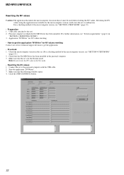
... AD SEL 134 CHGI SEL 135 CHG MON 160 XRST CHG IC 113 XEXT PWR 131 UDM 176 UDP 175 4FS SW Q603 VB REC DRIVER IC601 7 EFM VIO 8 4 CLK 20 RF1 VC 9 VC2 26 VG 36 19 INM1 VREC O1 10 11 L1 1 14 L1 2 VREC O2 15 VREC IN1... TP HA 33 6 FI 5 RI 3 OE 2 REC ON 1 SW HB 35 OUT B 38 OUT A 41 REGO1 VCO1 VG A SWITCH Q604,605 B OVER WRITE HEAD MZ-NF810/NF810CK REGO1 VCO1 L903 Q901 VCO2 UNREG D903 L904 L901 L902 D901 D902 VG POWER AMP IC901 43 REGO1 11 VCO1 DATA 58 SCK 60 CLK...
... AD SEL 134 CHGI SEL 135 CHG MON 160 XRST CHG IC 113 XEXT PWR 131 UDM 176 UDP 175 4FS SW Q603 VB REC DRIVER IC601 7 EFM VIO 8 4 CLK 20 RF1 VC 9 VC2 26 VG 36 19 INM1 VREC O1 10 11 L1 1 14 L1 2 VREC O2 15 VREC IN1... TP HA 33 6 FI 5 RI 3 OE 2 REC ON 1 SW HB 35 OUT B 38 OUT A 41 REGO1 VCO1 VG A SWITCH Q604,605 B OVER WRITE HEAD MZ-NF810/NF810CK REGO1 VCO1 L903 Q901 VCO2 UNREG D903 L904 L901 L902 D901 D902 VG POWER AMP IC901 43 REGO1 11 VCO1 DATA 58 SCK 60 CLK...
Service Manual
Page 50
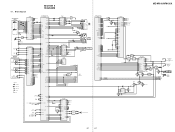
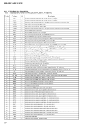
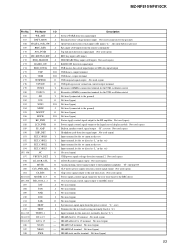
MZ-NF810/NF810CK 6-9. IC Pin Function Description • IC801 CXD2680-203GA (SYSTEM CONTROLLER, DIGITAL SIGNAL PROCESSOR) Pin No. 1 2 3 4 5 6 7 8 9 10 11 12 13 14 15 16 17 18 19 ... the RF amplifier O Tracking servo drive PWM signal output (-) to the coil driver O Tracking servo drive PWM signal output (+) to the coil driver O Focus servo drive PWM signal output (+) to the coil driver O Focus servo drive PWM signal output (-) to the coil driver O 176.4kHz clock signal output O Sled servo drive PWM signal output...
MZ-NF810/NF810CK 6-9. IC Pin Function Description • IC801 CXD2680-203GA (SYSTEM CONTROLLER, DIGITAL SIGNAL PROCESSOR) Pin No. 1 2 3 4 5 6 7 8 9 10 11 12 13 14 15 16 17 18 19 ... the RF amplifier O Tracking servo drive PWM signal output (-) to the coil driver O Tracking servo drive PWM signal output (+) to the coil driver O Focus servo drive PWM signal output (+) to the coil driver O Focus servo drive PWM signal output (-) to the coil driver O 176.4kHz clock signal output O Sled servo drive PWM signal output...
Service Manual
Page 51
... output enable signal output Not used (open) Laser power changeover signal output Not used (open) EFM encode data output for the record to the REC driver FMCK signal input Not used (connected to the ground) Tracking signal input/output Not used (open) L circuit signal output Not used (open) K-SHOCK circuit signal...) Power supply control signal output for the OP modulation Not used (open) Power supply control signal output for the OP laser Not used (open) 51 MZ-NF810/NF810CK Pin No.
... output enable signal output Not used (open) Laser power changeover signal output Not used (open) EFM encode data output for the record to the REC driver FMCK signal input Not used (connected to the ground) Tracking signal input/output Not used (open) L circuit signal output Not used (open) K-SHOCK circuit signal...) Power supply control signal output for the OP modulation Not used (open) Power supply control signal output for the OP laser Not used (open) 51 MZ-NF810/NF810CK Pin No.
Service Manual
Page 52
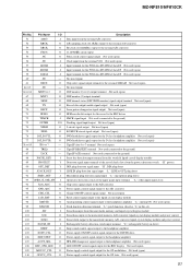
MZ-NF810/NF810CK Pin No. Pin Name I/O Description 111 BATT_CTL O Control signal output ... Strobe signal output to the liquid crystal display module 143 XRST_MTR_DRV O Reset control signal output to the motor driver "L": reset 144 XCS_NV O Chip select signal output to the nonvolatile memory 145 CHG_PWM O Output voltage control signal...control signal output for the D class headphone amplifier Not used (open) 150 XCS_REC_DRV O Chip select signal output to the REC driver Not used (open) 151 T_MARK _SW I T MARK (track mark) switch input terminal "L": track mark detection Not used (...
MZ-NF810/NF810CK Pin No. Pin Name I/O Description 111 BATT_CTL O Control signal output ... Strobe signal output to the liquid crystal display module 143 XRST_MTR_DRV O Reset control signal output to the motor driver "L": reset 144 XCS_NV O Chip select signal output to the nonvolatile memory 145 CHG_PWM O Output voltage control signal...control signal output for the D class headphone amplifier Not used (open) 150 XCS_REC_DRV O Chip select signal output to the REC driver Not used (open) 151 T_MARK _SW I T MARK (track mark) switch input terminal "L": track mark detection Not used (...
Service Manual
Page 53
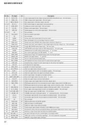
MZ-NF810/NF810CK Pin No. Description Set key WAKE detection signal input External battery voltage monitor input Not used (connected to the ground) Open button detection switch input (A/D ... to the real time clock Not used (open) Power supply control signal output for the over write head to the REC driver Over write head control signal output to the REC driver Not used (open) Not used (open) Not used (open) Not used (open) Not used (open) System reset signal input from...
MZ-NF810/NF810CK Pin No. Description Set key WAKE detection signal input External battery voltage monitor input Not used (connected to the ground) Open button detection switch input (A/D ... to the real time clock Not used (open) Power supply control signal output for the over write head to the REC driver Over write head control signal output to the REC driver Not used (open) Not used (open) Not used (open) Not used (open) Not used (open) System reset signal input from...

