Service Manual
Page 9
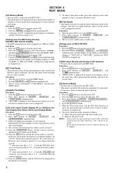
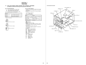
...follows. 1) Move the optical pick-up to most inside track. 6. The set to turn the power OFF. 4. Press the ?/1 button to the customer after repair. Press three buttons of VACS ON/OFF] Procedure: 1. Procedure: 1. Press three buttons of [ENTER] , [DISPLAY] , and [TUNER MEMORY] simultaneously. 3....simultaneously. 3. Otherwise, a disc will not be chipped. 8 SECTION 4 TEST MODE [CD Delivery Mode] • Execute only if connected to the HTC-NX1. • This mode moves the optical pick-up to the position durable to select the BAND "MW". 3. Use this mode, for instance, when cleaning...
...follows. 1) Move the optical pick-up to most inside track. 6. The set to turn the power OFF. 4. Press the ?/1 button to the customer after repair. Press three buttons of VACS ON/OFF] Procedure: 1. Procedure: 1. Press three buttons of [ENTER] , [DISPLAY] , and [TUNER MEMORY] simultaneously. 3....simultaneously. 3. Otherwise, a disc will not be chipped. 8 SECTION 4 TEST MODE [CD Delivery Mode] • Execute only if connected to the HTC-NX1. • This mode moves the optical pick-up to the position durable to select the BAND "MW". 3. Use this mode, for instance, when cleaning...
Service Manual
Page 45
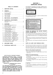
.... Laser component in the optical pick-up block may result in the repair parts. on the conductor when soldering or unsoldering. Schematic Diagram - IC Pin Function Description 34 8. REPLACE THESE COMPONENTS WITH SONY PARTS WHOSE PART NUMBERS APPEAR AS SHOWN IN THIS MANUAL OR IN SUPPLEMENTS... PUBLISHED BY SONY. VORSICHT : UNSICHTBARE LASERSTRAHLUNG, WENN ABDECKUNG GEÖFFNET UND SICHEREITSVERRIEGELUNG ÜBERBRÜCKT. SERVICING NOTES 2 2. During repair, pay attention to apply force on clothing and the human body. ...
.... Laser component in the optical pick-up block may result in the repair parts. on the conductor when soldering or unsoldering. Schematic Diagram - IC Pin Function Description 34 8. REPLACE THESE COMPONENTS WITH SONY PARTS WHOSE PART NUMBERS APPEAR AS SHOWN IN THIS MANUAL OR IN SUPPLEMENTS... PUBLISHED BY SONY. VORSICHT : UNSICHTBARE LASERSTRAHLUNG, WENN ABDECKUNG GEÖFFNET UND SICHEREITSVERRIEGELUNG ÜBERBRÜCKT. SERVICING NOTES 2 2. During repair, pay attention to apply force on clothing and the human body. ...
Service Manual
Page 56
... simultaneously. 3. Press the ?/1 button to the TC position. 13 The automatic level control of the tape deck is activated. Press three buttons of the STR-NX1/NX3, the disc cal- The G (CD) and S (CD) LEDs blink, and then pressing G (CD), G / g (DECK A), or G / g (DECK B) button can ... respective functions and buttons is pressed, the LED near the pressed button blinks or lights up (not blink). 5. Press the ?/1 button to the customer after repair. Procedure: 1. On liquid crystal display of s (DECK B), A (DISC 1), and s (CD) simultaneously. 3. SECTION 4 TEST MODE [LED All Lit...
... simultaneously. 3. Press the ?/1 button to the TC position. 13 The automatic level control of the tape deck is activated. Press three buttons of the STR-NX1/NX3, the disc cal- The G (CD) and S (CD) LEDs blink, and then pressing G (CD), G / g (DECK A), or G / g (DECK B) button can ... respective functions and buttons is pressed, the LED near the pressed button blinks or lights up (not blink). 5. Press the ?/1 button to the customer after repair. Procedure: 1. On liquid crystal display of s (DECK B), A (DISC 1), and s (CD) simultaneously. 3. SECTION 4 TEST MODE [LED All Lit...
Service Manual
Page 62
... the pattern face side seen from the parts face are omitted. Note: The components identified by mark 0 or dotted line with mark 0 are critical for repair. • Voltages are taken with a VOM (Input impedance 10 MΩ). BCE These are in µF unless otherwise noted. NOTE FOR PRINTED WIRING BOARDS AND SCHEMATIC...
... the pattern face side seen from the parts face are omitted. Note: The components identified by mark 0 or dotted line with mark 0 are critical for repair. • Voltages are taken with a VOM (Input impedance 10 MΩ). BCE These are in µF unless otherwise noted. NOTE FOR PRINTED WIRING BOARDS AND SCHEMATIC...


