Operating Instructions (primary manual)
Page 2
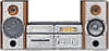
...intended to alert the user to operate this product will not occur in cabinet. Reorient or relocate the receiving antenna. - A/V control amplifier STR-NX1 - Do not install the appliance in a confined space, such as a CLASS 1 LASER product. Increase the separation between the equipment and ...the equipment into an outlet on the rear exterior. The MHC-NX1 consist of electric shock to comply with this equipment. To avoid electrical shock, do not expose the unit to constitute a risk of the following measures: - Speaker system SS-NX1 2 Refer servicing to the presence of ...
...intended to alert the user to operate this product will not occur in cabinet. Reorient or relocate the receiving antenna. - A/V control amplifier STR-NX1 - Do not install the appliance in a confined space, such as a CLASS 1 LASER product. Increase the separation between the equipment and ...the equipment into an outlet on the rear exterior. The MHC-NX1 consist of electric shock to comply with this equipment. To avoid electrical shock, do not expose the unit to constitute a risk of the following measures: - Speaker system SS-NX1 2 Refer servicing to the presence of ...
Operating Instructions (primary manual)
Page 42
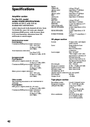
...Inputs VIDEO IN: (phono jacks) MD IN: (phono jacks) MIC: (mini jack) Outputs MD OUT: (phono jacks) PHONES: (stereo mini jack) FRONT SPEAKER: REAR SPEAKER: SUPER WOOFER: voltage 250 mV, impedance 47 kilohms voltage 450 mV, impedance 47 kilohms sensitivity 1 mV, impedance 10 kilohms voltage 250 mV impedance 1 kilohms accepts... system Frequency response (DOLBY NR OFF) Wow and flutter 4-track 2-channel stereo 40 - 13,000 Hz (±3 dB), using Sony TYPE I cassette 40 - 14,000 Hz (±3 dB), using Sony TYPE II cassette ±0.15% W.Peak (IEC) 0.1% W.RMS (NAB) ±0.2% W.Peak (DIN) 42
...Inputs VIDEO IN: (phono jacks) MD IN: (phono jacks) MIC: (mini jack) Outputs MD OUT: (phono jacks) PHONES: (stereo mini jack) FRONT SPEAKER: REAR SPEAKER: SUPER WOOFER: voltage 250 mV, impedance 47 kilohms voltage 450 mV, impedance 47 kilohms sensitivity 1 mV, impedance 10 kilohms voltage 250 mV impedance 1 kilohms accepts... system Frequency response (DOLBY NR OFF) Wow and flutter 4-track 2-channel stereo 40 - 13,000 Hz (±3 dB), using Sony TYPE I cassette 40 - 14,000 Hz (±3 dB), using Sony TYPE II cassette ±0.15% W.Peak (IEC) 0.1% W.RMS (NAB) ±0.2% W.Peak (DIN) 42
Service Manual
Page 1
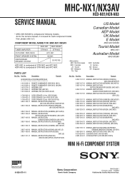
...979-11 Sony Corporation Home Audio Company 99H001688-1 Printed in Japan ©1999.8 Published by Quality Assurance Dept. MHC-NX1/NX3AV HCD-NX1/HCR-NX3 SERVICE MANUAL • MHC-NX1/NX3AV is composed of STR-NX3 and HTC-NX1. HCR-NX3 is composed of STR-NX1 and HTC-NX1. No..... COMPONENT MODEL NAME FOR MHC-NX1/NX3AV US Model Canadian Model AEP Model UK Model E Model MHC-NX1/NX3AV TUNER,AMPLIFIER MHC-NX1 STR-NX1 MHC-NX3AV STR-NX3 Tourist Model MHC-NX1 CD PLAYER ,TAPE DECK FRONT SPEAKER SYSTEM CENTER/REAR SPEAKER SYSTEM HTC-NX1 SS-NX1 SS-RC100 HCD-NX1 is issued for each component...
...979-11 Sony Corporation Home Audio Company 99H001688-1 Printed in Japan ©1999.8 Published by Quality Assurance Dept. MHC-NX1/NX3AV HCD-NX1/HCR-NX3 SERVICE MANUAL • MHC-NX1/NX3AV is composed of STR-NX3 and HTC-NX1. HCR-NX3 is composed of STR-NX1 and HTC-NX1. No..... COMPONENT MODEL NAME FOR MHC-NX1/NX3AV US Model Canadian Model AEP Model UK Model E Model MHC-NX1/NX3AV TUNER,AMPLIFIER MHC-NX1 STR-NX1 MHC-NX3AV STR-NX3 Tourist Model MHC-NX1 CD PLAYER ,TAPE DECK FRONT SPEAKER SYSTEM CENTER/REAR SPEAKER SYSTEM HTC-NX1 SS-NX1 SS-RC100 HCD-NX1 is issued for each component...
Service Manual
Page 5
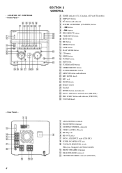
... - 12 3 4 5 6 7 8 q; SECTION 2 GENERAL 1 TIMER indicator (US, Canadian, AEP and UK models) 2 DISPLAY button 3 ?/1 button and indicator 4 POWER SAVE/DEMO (STANDBY) button 5 - FRONT SPEAKER terminals qa REAR SPEAKER terminals qs CENTER SPEAKER terminals (STR-NX3) • LOCATION OF CONTROLS - m button 6 + M button qk 7 FILE SELECT button ql 8 VIDEO/DVD button w; 9 EDIT button q; qa qs 4 1 AM ANTENNA...
... - 12 3 4 5 6 7 8 q; SECTION 2 GENERAL 1 TIMER indicator (US, Canadian, AEP and UK models) 2 DISPLAY button 3 ?/1 button and indicator 4 POWER SAVE/DEMO (STANDBY) button 5 - FRONT SPEAKER terminals qa REAR SPEAKER terminals qs CENTER SPEAKER terminals (STR-NX3) • LOCATION OF CONTROLS - m button 6 + M button qk 7 FILE SELECT button ql 8 VIDEO/DVD button w; 9 EDIT button q; qa qs 4 1 AM ANTENNA...
Service Manual
Page 25
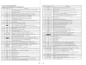
...from the spectrum analyzer band-pass filter (IC401) (for 40 Hz) 3 F RELAY O Speaker protect relay drive signal output for the front side speaker "H": relay on 4 R RELAY O Speaker protect relay drive signal output for the rear side speaker "H": relay on 5 SIRCS I Remote control signal input from the remote control receiver (IC601...byte selection signal input terminal Fixed at "L" in this set 18 WAKE UP O Wakeup control signal output to the CPU on the HTC-NX1 "H" active 19 PHONES MUTE O Muting on/off control signal output terminal "L": muting on Not used (open) 20 RDS INT I RDS...
...from the spectrum analyzer band-pass filter (IC401) (for 40 Hz) 3 F RELAY O Speaker protect relay drive signal output for the front side speaker "H": relay on 4 R RELAY O Speaker protect relay drive signal output for the rear side speaker "H": relay on 5 SIRCS I Remote control signal input from the remote control receiver (IC601...byte selection signal input terminal Fixed at "L" in this set 18 WAKE UP O Wakeup control signal output to the CPU on the HTC-NX1 "H" active 19 PHONES MUTE O Muting on/off control signal output terminal "L": muting on Not used (open) 20 RDS INT I RDS...
Service Manual
Page 38
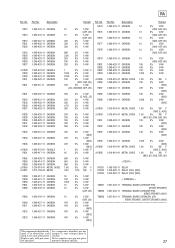
...4W 33K 5% 1/4W 68K 5% 1/4W 2.2K 5% 1/4W 22K 5% 1/4W 10K 5% 1/4W 22K 5% 1/4W 1 5% 1/4W F 100K 5% 1/4W 100K 5% 1/4W 10K 5% 1/4W (NX1: AEP, UK) 12K 5% 1/4W (US, CND/NX3: AEP, UK) 18K 5% 1/4W (E, AUS, JE) 15K 5% 1/4W 33K 5% 1/4W 4.7K 5% 1/4W 22K 5% 1/4W 33K... < TERMINAL > TM801 1-537-240-11 TERMINAL BOARD (CHECKER PIN) (FRONT SPEAKER) TM802 1-537-240-11 TERMINAL BOARD (CHECKER PIN) (REAR SPEAKER) (NX1) TM802 1-537-510-11 TERMINAL BOARD (SPEAKER) (6P) (REAR SPEAKER, CENTER SPEAKER) (NX3) The components identified by Les composants identifiés par une mark ...
...4W 33K 5% 1/4W 68K 5% 1/4W 2.2K 5% 1/4W 22K 5% 1/4W 10K 5% 1/4W 22K 5% 1/4W 1 5% 1/4W F 100K 5% 1/4W 100K 5% 1/4W 10K 5% 1/4W (NX1: AEP, UK) 12K 5% 1/4W (US, CND/NX3: AEP, UK) 18K 5% 1/4W (E, AUS, JE) 15K 5% 1/4W 33K 5% 1/4W 4.7K 5% 1/4W 22K 5% 1/4W 33K... < TERMINAL > TM801 1-537-240-11 TERMINAL BOARD (CHECKER PIN) (FRONT SPEAKER) TM802 1-537-240-11 TERMINAL BOARD (CHECKER PIN) (REAR SPEAKER) (NX1) TM802 1-537-510-11 TERMINAL BOARD (SPEAKER) (6P) (REAR SPEAKER, CENTER SPEAKER) (NX3) The components identified by Les composants identifiés par une mark ...


