Operating Instructions (primary manual)
Page 2
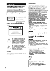
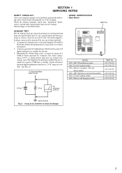
... This equipment generates, uses, and can be of sufficient magnitude to persons. Increase the separation between the equipment and receiver. - The MHC-NX1 consist of optical instruments with the instructions, may be determined by one or more of electric shock to constitute a risk of the following ...components: - CD player/Stereo cassette deck HTC-NX1 - To avoid electrical shock, do not expose the unit to Part 15 of the FCC Rules. CAUTION The use of the following measures: - CAUTION You are cautioned that...
... This equipment generates, uses, and can be of sufficient magnitude to persons. Increase the separation between the equipment and receiver. - The MHC-NX1 consist of optical instruments with the instructions, may be determined by one or more of electric shock to constitute a risk of the following ...components: - CD player/Stereo cassette deck HTC-NX1 - To avoid electrical shock, do not expose the unit to Part 15 of the FCC Rules. CAUTION The use of the following measures: - CAUTION You are cautioned that...
Operating Instructions (primary manual)
Page 38
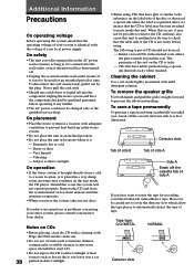
...and have any questions or problems concerning your stereo system, please consult your local power supply. Rental or used : - Very humid - Be sure to parts inside the CD player. Notes on the CD is placed in a very damp room, moisture may become attached to check that the CD or label...operating the system, check that feels tacky when touched. Remove the CD and leave the system turned on the label side of your nearest Sony dealer. The following types of CD should not be careful not to cover the detector slots which allow the tape player to automatically detect ...
...and have any questions or problems concerning your stereo system, please consult your local power supply. Rental or used : - Very humid - Be sure to parts inside the CD player. Notes on the CD is placed in a very damp room, moisture may become attached to check that the CD or label...operating the system, check that feels tacky when touched. Remove the CD and leave the system turned on the label side of your nearest Sony dealer. The following types of CD should not be careful not to cover the detector slots which allow the tape player to automatically detect ...

Operating Instructions (primary manual)
Page 39
... any problem using a tape longer than half a day. the sound is turned off. Demagnetizing the tape heads Demagnetize the tape heads and the metal parts that the power cord is a power outage lasting longer than 90 minutes The tape is very elastic. First, check that have set the timer, also... redo "Waking up any problem persist, consult your nearest Sony dealer. The tape may get entangled in the power cord or if there is connected firmly and the speakers are connected. •Insert only the...
... any problem using a tape longer than half a day. the sound is turned off. Demagnetizing the tape heads Demagnetize the tape heads and the metal parts that the power cord is a power outage lasting longer than 90 minutes The tape is very elastic. First, check that have set the timer, also... redo "Waking up any problem persist, consult your nearest Sony dealer. The tape may get entangled in the power cord or if there is connected firmly and the speakers are connected. •Insert only the...
Service Manual
Page 1
.../SX15) MINI Hi-Fi COMPONENT SYSTEM MICROFILM 9-928-979-11 Sony Corporation Home Audio Company 99H001688-1 Printed in Japan ©1999.8 Published by Quality Assurance Dept. MHC-NX1/NX3AV HCD-NX1/HCR-NX3 SERVICE MANUAL • MHC-NX1/NX3AV is composed of STR-NX3 and HTC-NX1. No. Part No. As for the service manual, it . COMPONENT MODEL...
.../SX15) MINI Hi-Fi COMPONENT SYSTEM MICROFILM 9-928-979-11 Sony Corporation Home Audio Company 99H001688-1 Printed in Japan ©1999.8 Published by Quality Assurance Dept. MHC-NX1/NX3AV HCD-NX1/HCR-NX3 SERVICE MANUAL • MHC-NX1/NX3AV is composed of STR-NX3 and HTC-NX1. No. Part No. As for the service manual, it . COMPONENT MODEL...
Service Manual
Page 4
... can be measured by means of three methods. 1. A battery-operated AC milliammeter. A) To Exposed Metal Parts on Set MODEL NX1: AEP, UK and Korean models NX1: US and Canadian models NX1: Malaysia, Singapore, Thai and Tourist models NX3: AEP, UK, Korean and Australian models NX3: US and... Canadian models NX3: Malaysia and Singapore models PART No. 4-221-391-0[] 4-221-391-1[] 4-221-391-2[] 4-221-391-3[] 4-221-391-4[] 4-221-391-5[] 0.15 ...
... can be measured by means of three methods. 1. A battery-operated AC milliammeter. A) To Exposed Metal Parts on Set MODEL NX1: AEP, UK and Korean models NX1: US and Canadian models NX1: Malaysia, Singapore, Thai and Tourist models NX3: AEP, UK, Korean and Australian models NX3: US and... Canadian models NX3: Malaysia and Singapore models PART No. 4-221-391-0[] 4-221-391-1[] 4-221-391-2[] 4-221-391-3[] 4-221-391-4[] 4-221-391-5[] 0.15 ...
Service Manual
Page 12
... • U : B+ Line. • V : B- Note on the conductor side. • b : Pattern from the conductor side. • x : parts mounted on Schematic Diagram: • All capacitors are omitted. Replace only with a VOM (Input impedance 10 MΩ). no -signal (detuned) conditions. tion tolerances. ...• Waveforms are taken with part number specified. Voltage variations may be noted due to ground under no mark : TUNER (FM) • Voltages are taken with respect...
... • U : B+ Line. • V : B- Note on the conductor side. • b : Pattern from the conductor side. • x : parts mounted on Schematic Diagram: • All capacitors are omitted. Replace only with a VOM (Input impedance 10 MΩ). no -signal (detuned) conditions. tion tolerances. ...• Waveforms are taken with part number specified. Voltage variations may be noted due to ground under no mark : TUNER (FM) • Voltages are taken with respect...
Service Manual
Page 27
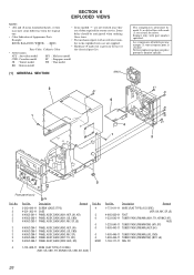
...13 CORE) (NX1: US, CND, TH, KR/NX3: US, CND, KR, AUS) 26 KNOB, BALANCE (WHITE) . . . (RED) ber in the last of Appearance Parts these items. Example: • The mechanical parts with mark 0 are critical for routine service. Replace only with part number specified....1 #1 6 4 1 #1 #1 #1 #1 #1 3 5 Front panel ass'y #4 Ref. Some one. SECTION 6 EXPLODED VIEWS NOTE: • -XX and -X mean standardized parts, so they • Items marked "*" are not stocked since they may have some difference from the original are not supplied. ↑ ↑ • Hardware (# mark...
...13 CORE) (NX1: US, CND, TH, KR/NX3: US, CND, KR, AUS) 26 KNOB, BALANCE (WHITE) . . . (RED) ber in the last of Appearance Parts these items. Example: • The mechanical parts with mark 0 are critical for routine service. Replace only with part number specified....1 #1 6 4 1 #1 #1 #1 #1 #1 3 5 Front panel ass'y #4 Ref. Some one. SECTION 6 EXPLODED VIEWS NOTE: • -XX and -X mean standardized parts, so they • Items marked "*" are not stocked since they may have some difference from the original are not supplied. ↑ ↑ • Hardware (# mark...
Service Manual
Page 28
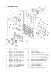
... supplied not supplied 67 64 66 52 Ref. No. 51 52 53 53 53 51 Part No. (2) FRONT PANEL SECTION 53 56 55 58 57 not supplied 60 LCD601 59 #1...4951-814-1 KNOB (VOL) ASSY X-4951-831-1 JOG ASSY, KNOB X-4951-812-1 PANEL ASSY, FRONT (NX1: AEP, UK) X-4951-815-1 PANEL ASSY, FRONT (NX1: E, JE) X-4951-816-1 PANEL ASSY, FRONT (NX3: E, AUS) Ref. Description 4-221-369-01 ... US, CND, AEP, UK) 65 A-4426-275-A PANEL BOARD, COMPLETE (NX3: E, AUS) 65 A-4426-927-A PANEL BOARD, COMPLETE (NX1: TH) 66 4-221-363-01 KNOB, MICROPHONE 67 1-769-886-11 WIRE (FLAT TYPE) (7 CORE) 68 4-951-620-01 SCREW (2....
... supplied not supplied 67 64 66 52 Ref. No. 51 52 53 53 53 51 Part No. (2) FRONT PANEL SECTION 53 56 55 58 57 not supplied 60 LCD601 59 #1...4951-814-1 KNOB (VOL) ASSY X-4951-831-1 JOG ASSY, KNOB X-4951-812-1 PANEL ASSY, FRONT (NX1: AEP, UK) X-4951-815-1 PANEL ASSY, FRONT (NX1: E, JE) X-4951-816-1 PANEL ASSY, FRONT (NX3: E, AUS) Ref. Description 4-221-369-01 ... US, CND, AEP, UK) 65 A-4426-275-A PANEL BOARD, COMPLETE (NX3: E, AUS) 65 A-4426-927-A PANEL BOARD, COMPLETE (NX1: TH) 66 4-221-363-01 KNOB, MICROPHONE 67 1-769-886-11 WIRE (FLAT TYPE) (7 CORE) 68 4-951-620-01 SCREW (2....
Service Manual
Page 31
...: MY, SP) A-4426-527-A MAIN BOARD, COMPLETE (NX3: KR, AUS) A-4426-556-A MAIN BOARD, COMPLETE (NX1: JE) A-4426-559-A MAIN BOARD, COMPLETE (NX1: KR) A-4426-931-A MAIN BOARD, COMPLETE (NX1: TH) C141 C151 C152 C153 C161 1-126-959-11 ELECT 1-162-286-31 CERAMIC 1-162-286-31 CERAMIC 1-162...Metal-film resistor. Replace only with mark 0 are in the diagrams or the components used on the set. • -XX and -X mean standardized parts, so they are seldom required for safety. Description • Items marked "*" are not stocked since they may be anticipated when ordering these items. &#...
...: MY, SP) A-4426-527-A MAIN BOARD, COMPLETE (NX3: KR, AUS) A-4426-556-A MAIN BOARD, COMPLETE (NX1: JE) A-4426-559-A MAIN BOARD, COMPLETE (NX1: KR) A-4426-931-A MAIN BOARD, COMPLETE (NX1: TH) C141 C151 C152 C153 C161 1-126-959-11 ELECT 1-162-286-31 CERAMIC 1-162-286-31 CERAMIC 1-162...Metal-film resistor. Replace only with mark 0 are in the diagrams or the components used on the set. • -XX and -X mean standardized parts, so they are seldom required for safety. Description • Items marked "*" are not stocked since they may be anticipated when ordering these items. &#...
Service Manual
Page 37
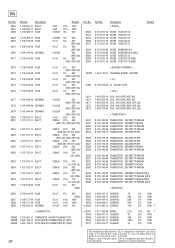
...5% 1/4W 560 5% 1/4W 56K 5% 1/4W 100 5% 1/4W F < CONNECTOR > CN802 1-778-981-11 CONNECTOR, BOARD TO BOARD 13P CN808 1-691-766-11 PLUG (MICRO CONNECTOR) 4P (NX1) CN808 1-691-768-11 PLUG (MICRO CONNECTOR) 6P (NX3) 0 R807 R808 R809 R810 R811 1-217-156-00 METAL 1-249-417-11 CARBON 1-249-431-11... identified by Les composants identifiés par une mark 0 or dotted line with part num- portant le numéro spécifié. C856 C857 C858 Part No. D802 D821 D831 D852 D871 D881 D882 D883 D884 D885 Part No. No. No. sécurité. PA Ref. Description 1-128-560-11 ...
...5% 1/4W 560 5% 1/4W 56K 5% 1/4W 100 5% 1/4W F < CONNECTOR > CN802 1-778-981-11 CONNECTOR, BOARD TO BOARD 13P CN808 1-691-766-11 PLUG (MICRO CONNECTOR) 4P (NX1) CN808 1-691-768-11 PLUG (MICRO CONNECTOR) 6P (NX3) 0 R807 R808 R809 R810 R811 1-217-156-00 METAL 1-249-417-11 CARBON 1-249-431-11... identified by Les composants identifiés par une mark 0 or dotted line with part num- portant le numéro spécifié. C856 C857 C858 Part No. D802 D821 D831 D852 D871 D881 D882 D883 D884 D885 Part No. No. No. sécurité. PA Ref. Description 1-128-560-11 ...
Service Manual
Page 38
... Replace only with marque 0 sont critiques pour la mark 0 are critical for safety. portant le numéro spécifié. 37 Part No. sécurité. PA Ref. Description 1-260-076-11 CARBON 1-260-076-11 CARBON 1-249-437-11 CARBON 1-249-435-11 ...5% 1/4W 33K 5% 1/4W 33K 5% 1/4W 68K 5% 1/4W 2.2K 5% 1/4W 22K 5% 1/4W 10K 5% 1/4W 22K 5% 1/4W 1 5% 1/4W F 100K 5% 1/4W 100K 5% 1/4W 10K 5% 1/4W (NX1: AEP, UK) 12K 5% 1/4W (US, CND/NX3: AEP, UK) 18K 5% 1/4W (E, AUS, JE) 15K 5% 1/4W 33K 5% 1/4W 4.7K 5% 1/4W 22K 5% 1/4W 33K 5% 1/4W 10K 5% ...
... Replace only with marque 0 sont critiques pour la mark 0 are critical for safety. portant le numéro spécifié. 37 Part No. sécurité. PA Ref. Description 1-260-076-11 CARBON 1-260-076-11 CARBON 1-249-437-11 CARBON 1-249-435-11 ...5% 1/4W 33K 5% 1/4W 33K 5% 1/4W 68K 5% 1/4W 2.2K 5% 1/4W 22K 5% 1/4W 10K 5% 1/4W 22K 5% 1/4W 1 5% 1/4W F 100K 5% 1/4W 100K 5% 1/4W 10K 5% 1/4W (NX1: AEP, UK) 12K 5% 1/4W (US, CND/NX3: AEP, UK) 18K 5% 1/4W (E, AUS, JE) 15K 5% 1/4W 33K 5% 1/4W 4.7K 5% 1/4W 22K 5% 1/4W 33K 5% 1/4W 10K 5% ...
Service Manual
Page 39
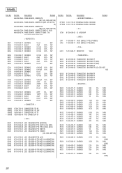
C651 C652 C653 C654 C655 Part No. No. Part No. Description < GROUND TERMINAL > EPT601 1-537-770-21 TERMINAL BOARD,...270 5% 1/4W 330 5% 1/4W 330 5% 1/4W (NX3) 38 Description Remark A-4426-226-A PANEL BOARD, COMPLETE (NX1: US, CND, AEP, UK) A-4426-249-A PANEL BOARD, COMPLETE (NX1: MY, SP, KR, JE) A-4426-258-A PANEL BOARD, COMPLETE (NX3: US, CND, AEP, UK) A-...4426-275-A PANEL BOARD, COMPLETE (NX3: E, AUS) A-4426-927-A PANEL BOARD, COMPLETE (NX1: TH) < CAPACITOR > 1-164-159-11 CERAMIC 1-104-664-11 ELECT 1-162-306-11 CERAMIC 1-162-306-11 CERAMIC 1-162-...
C651 C652 C653 C654 C655 Part No. No. Part No. Description < GROUND TERMINAL > EPT601 1-537-770-21 TERMINAL BOARD,...270 5% 1/4W 330 5% 1/4W 330 5% 1/4W (NX3) 38 Description Remark A-4426-226-A PANEL BOARD, COMPLETE (NX1: US, CND, AEP, UK) A-4426-249-A PANEL BOARD, COMPLETE (NX1: MY, SP, KR, JE) A-4426-258-A PANEL BOARD, COMPLETE (NX3: US, CND, AEP, UK) A-...4426-275-A PANEL BOARD, COMPLETE (NX3: E, AUS) A-4426-927-A PANEL BOARD, COMPLETE (NX1: TH) < CAPACITOR > 1-164-159-11 CERAMIC 1-104-664-11 ELECT 1-162-306-11 CERAMIC 1-162-306-11 CERAMIC 1-162-...
Service Manual
Page 40
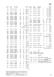
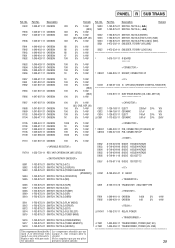
Part No. Description Remark 330 5% 1/4W S620 1-762-875-21 SWITCH, TACTILE (+ M) (NX3) S621 1-762-875-21 SWITCH, TACTILE (- Ne les remplacer que ...STEREO/MONO) 1-762-875-21 SWITCH, TACTILE (TUNER MEMORY) 1-762-875-21 SWITCH, TACTILE (GROOVE) The components identified by mark 0 or dotted line with part number specified. Description R633 1-249-411-11 CARBON R636 1-249-411-11 CARBON R637 1-249-411-11 CARBON R638 1-249-411-11 CARBON R641 R642... 1-249-429-11 CARBON 1-249-417-11 CARBON Remark Ref. Replace only with mark 0 are critical for safety. PANEL R SUB TRANS Ref. Part No.
Part No. Description Remark 330 5% 1/4W S620 1-762-875-21 SWITCH, TACTILE (+ M) (NX3) S621 1-762-875-21 SWITCH, TACTILE (- Ne les remplacer que ...STEREO/MONO) 1-762-875-21 SWITCH, TACTILE (TUNER MEMORY) 1-762-875-21 SWITCH, TACTILE (GROOVE) The components identified by mark 0 or dotted line with part number specified. Description R633 1-249-411-11 CARBON R636 1-249-411-11 CARBON R637 1-249-411-11 CARBON R638 1-249-411-11 CARBON R641 R642... 1-249-429-11 CARBON 1-249-417-11 CARBON Remark Ref. Replace only with mark 0 are critical for safety. PANEL R SUB TRANS Ref. Part No.
Service Manual
Page 41
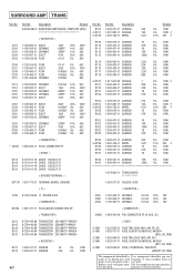
...FUSE T8AL/250V (NX3: MY, SP) 1-533-311-11 FUSE, GLASS CYLINDRICAL 8A/125V (NX1: US, CND) 1-533-949-31 FUSE, CYLINDRICAL T8AL/250V (EXCEPT US, CND) The components identified by mark 0 or dotted line with part number specified. Les composants identifiés par une marque 0 sont critiques pour la sé... R109 R110 R111 R112 R113 R114 R115 R116 R117 R119 0 R120 R121 R130 R151 R152 R153 0 R157 0 R158 R159 R160 R161 R162 R163 R181 R182 Part No. Description Remark A-4426-260-A SURROUND AMP BOARD, COMPLETE (NX3 < CAPACITOR > 1-128-582-11 ELECT 1-162-292-31 CERAMIC 1-162-286-31 CERAMIC 1-...
...FUSE T8AL/250V (NX3: MY, SP) 1-533-311-11 FUSE, GLASS CYLINDRICAL 8A/125V (NX1: US, CND) 1-533-949-31 FUSE, CYLINDRICAL T8AL/250V (EXCEPT US, CND) The components identified by mark 0 or dotted line with part number specified. Les composants identifiés par une marque 0 sont critiques pour la sé... R109 R110 R111 R112 R113 R114 R115 R116 R117 R119 0 R120 R121 R130 R151 R152 R153 0 R157 0 R158 R159 R160 R161 R162 R163 R181 R182 Part No. Description Remark A-4426-260-A SURROUND AMP BOARD, COMPLETE (NX3 < CAPACITOR > 1-128-582-11 ELECT 1-162-292-31 CERAMIC 1-162-286-31 CERAMIC 1-...
Service Manual
Page 42
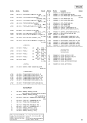
...) (25 CORE) 67 1-769-886-11 WIRE (FLAT TYPE) (7 CORE) The components identified by Les composants identifiés par une mark 0 or dotted line with part num- Ne les remplacer que par une pièce ber specified. sécurité. TRANS Ref. No. 0 F962 0 F962 0 F963 0 F963 0 F964 0 ... with marque 0 sont critiques pour la mark 0 are critical for safety. No. 69 0 104 0 104 0 104 0 104 Part No. Description Remark 1-533-311-11 FUSE, GLASS CYLINDRICAL 8A/125V (NX1: US, CND) 1-533-949-31 FUSE, CYLINDRICAL T8AL/250V (EXCEPT US, CND) 1-533-312-11 FUSE, GLASS CYLINDRICAL 10A/125V...
...) (25 CORE) 67 1-769-886-11 WIRE (FLAT TYPE) (7 CORE) The components identified by Les composants identifiés par une mark 0 or dotted line with part num- Ne les remplacer que par une pièce ber specified. sécurité. TRANS Ref. No. 0 F962 0 F962 0 F963 0 F963 0 F964 0 ... with marque 0 sont critiques pour la mark 0 are critical for safety. No. 69 0 104 0 104 0 104 0 104 Part No. Description Remark 1-533-311-11 FUSE, GLASS CYLINDRICAL 8A/125V (NX1: US, CND) 1-533-949-31 FUSE, CYLINDRICAL T8AL/250V (EXCEPT US, CND) 1-533-312-11 FUSE, GLASS CYLINDRICAL 10A/125V...
Service Manual
Page 45
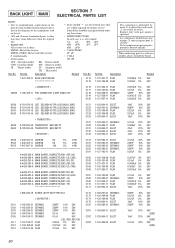
...- Schematic Diagram - Schematic Diagram - Printed Wiring Boards - Schematic Diagram - ELECTRICAL PARTS LIST 44 SAFETY-RELATED COMPONENT WARNING!! NE REMPLACER CES COMPOSANTS QUE PAR DES PIÈCES SONY DONT LES NUMÉROS SONT DONNÉS DANS CE MANUEL OU DANS LES SUPPL... Board 25 7-8. Schematic Diagram - OR DOTTED LINE WITH MARK ! REPLACE THESE COMPONENTS WITH SONY PARTS WHOSE PART NUMBERS APPEAR AS SHOWN IN THIS MANUAL OR IN SUPPLEMENTS PUBLISHED BY SONY. The following caution label is classified as to be handled with care. VORSICHT : UNSICHTBARE LASERSTRAHLUNG...
...- Schematic Diagram - Schematic Diagram - Printed Wiring Boards - Schematic Diagram - ELECTRICAL PARTS LIST 44 SAFETY-RELATED COMPONENT WARNING!! NE REMPLACER CES COMPOSANTS QUE PAR DES PIÈCES SONY DONT LES NUMÉROS SONT DONNÉS DANS CE MANUEL OU DANS LES SUPPL... Board 25 7-8. Schematic Diagram - OR DOTTED LINE WITH MARK ! REPLACE THESE COMPONENTS WITH SONY PARTS WHOSE PART NUMBERS APPEAR AS SHOWN IN THIS MANUAL OR IN SUPPLEMENTS PUBLISHED BY SONY. The following caution label is classified as to be handled with care. VORSICHT : UNSICHTBARE LASERSTRAHLUNG...
Service Manual
Page 53
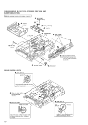
CHASSIS (MOLD B) SECTION, STOCKER SECTION AND SLIDER (SELECTION) Note: In mounting the parts, refer to page 11 and 12. 6 two screws (PTPWH M2.6) 5 stocker section 7 slider (selection) 8 washer pulley (LD) 9 compression spring 1 three screws (BVTP M2.6) 4 two step ...
CHASSIS (MOLD B) SECTION, STOCKER SECTION AND SLIDER (SELECTION) Note: In mounting the parts, refer to page 11 and 12. 6 two screws (PTPWH M2.6) 5 stocker section 7 slider (selection) 8 washer pulley (LD) 9 compression spring 1 three screws (BVTP M2.6) 4 two step ...
Service Manual
Page 57
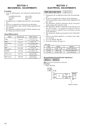
... Head Azimuth Adjustment DECK A DECK B Note: Perform this service manual. (As a general rule, playback circuit adjustment should be set PFJ-1 or STR-NX1/ NX3 level meter + - After the adjustments, apply suitable locking compound to 143 g • cm (0.99 - 1.99 oz • inch) ...100 g or more (3.53 oz or more) SECTION 6 ELECTRICAL ADJUSTMENTS TAPE DECK SECTION 0 dB=0.775 V 1. Set to the parts adjust. 4. Clean the following parts with a denatured alcohol-moistened swab: record/playback heads pinch rollers erase head rubber belts capstan idlers 2. Do not use a magnetized...
... Head Azimuth Adjustment DECK A DECK B Note: Perform this service manual. (As a general rule, playback circuit adjustment should be set PFJ-1 or STR-NX1/ NX3 level meter + - After the adjustments, apply suitable locking compound to 143 g • cm (0.99 - 1.99 oz • inch) ...100 g or more (3.53 oz or more) SECTION 6 ELECTRICAL ADJUSTMENTS TAPE DECK SECTION 0 dB=0.775 V 1. Set to the parts adjust. 4. Clean the following parts with a denatured alcohol-moistened swab: record/playback heads pinch rollers erase head rubber belts capstan idlers 2. Do not use a magnetized...
Service Manual
Page 60
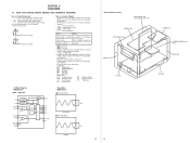
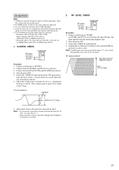
... the lead wire connected in order given. 2. Use YEDS-18 disc (3-702-101-01) unless otherwise indicated. 3. Use an oscilloscope with connector) (Part No. Connect oscilloscope to TP (RF). Turn the power ON. 5. tuate the focus search. (Actuate the focus search when disc tray is symmetrical ... lens by an applicator with neutral detergent when the signal level is correct or not. Use the following checks. 5. J-2501-011-B) Relay connector (Part No. Connect between A and B. Connect oscilloscope to TP (FEO). 2. Confirm that the shape " " can be clearly distinguished at the edge of...
... the lead wire connected in order given. 2. Use YEDS-18 disc (3-702-101-01) unless otherwise indicated. 3. Use an oscilloscope with connector) (Part No. Connect oscilloscope to TP (RF). Turn the power ON. 5. tuate the focus search. (Actuate the focus search when disc tray is symmetrical ... lens by an applicator with neutral detergent when the signal level is correct or not. Use the following checks. 5. J-2501-011-B) Relay connector (Part No. Connect between A and B. Connect oscilloscope to TP (FEO). 2. Confirm that the shape " " can be clearly distinguished at the edge of...
Service Manual
Page 62
... due to normal production tolerances. • Waveforms are taken with mark 0 are critical for safety. BE Note on the pattern face side seen from the parts face are in Ω and 1/4 W or less unless otherwise specified. • f : internal component. • 5 : fusible resistor. • C : panel ...: Pattern from the side which enables seeing. (The other layers' patterns are not indicated.) Caution: Pattern face side: (Side B) Parts face side: (Side A) Parts on Schematic Diagram: • All capacitors are omitted. Ne les remplacer que par une pièce portant le numéro sp...
... due to normal production tolerances. • Waveforms are taken with mark 0 are critical for safety. BE Note on the pattern face side seen from the parts face are in Ω and 1/4 W or less unless otherwise specified. • f : internal component. • 5 : fusible resistor. • C : panel ...: Pattern from the side which enables seeing. (The other layers' patterns are not indicated.) Caution: Pattern face side: (Side B) Parts face side: (Side A) Parts on Schematic Diagram: • All capacitors are omitted. Ne les remplacer que par une pièce portant le numéro sp...


