
Operating Instructions
Page 3
... communications. KLV-32U100M KLV-40U100M SONY WALL-MOUNT BRACKET MODEL NO. Safety s Operate the unit only on the cord. s The plug is connected. s If you are not of a reflective material. s Increase the separation between the equipment and receiver. s Do not install the unit in a hot or humid place, or in a place subject to Part 15 of the FCC Rules. SU-WL31 (KLV-32U100M) SU-WL51 (KLV-40U100M) To...
... communications. KLV-32U100M KLV-40U100M SONY WALL-MOUNT BRACKET MODEL NO. Safety s Operate the unit only on the cord. s The plug is connected. s If you are not of a reflective material. s Increase the separation between the equipment and receiver. s Do not install the unit in a hot or humid place, or in a place subject to Part 15 of the FCC Rules. SU-WL31 (KLV-32U100M) SU-WL51 (KLV-40U100M) To...

Operating Instructions
Page 5
... type of electrical power supplied to dripping or splashing and no objects filled with liquids, such as thinner or benzine for long periods of time, unplug it from the unit with a protective earthing connection. If the AC power cord is damaged, stop using a chemically pretreated cloth, please follow the instruction provided on the unit or described in the operating instructions or service manual...
... type of electrical power supplied to dripping or splashing and no objects filled with liquids, such as thinner or benzine for long periods of time, unplug it from the unit with a protective earthing connection. If the AC power cord is damaged, stop using a chemically pretreated cloth, please follow the instruction provided on the unit or described in the operating instructions or service manual...

Operating Instructions
Page 6
..., or laundry tub, in use plugged sets near a swimming pool, etc. Quick stops, excessive force, and uneven surfaces may damage the screen surface. If the unit is installed or removed from the unit. Medical institution Do not place this apparatus must be moved with the installation instructions. It may cause malfunction of light (red, blue, or green) may appear or bright points...
..., or laundry tub, in use plugged sets near a swimming pool, etc. Quick stops, excessive force, and uneven surfaces may damage the screen surface. If the unit is installed or removed from the unit. Medical institution Do not place this apparatus must be moved with the installation instructions. It may cause malfunction of light (red, blue, or green) may appear or bright points...

Operating Instructions
Page 9
... Bottom Panel 16 Connecting the Unit Making Video and Audio Connections 17 Satellite Receiver 18 VCR and Cable 19 HD Equipment 20 DVD Player 22 HDMI-Equipped Device 24 DVI-HDTV-Equipped Device 25 Personal Computer 26 Camcorder or Video Game Equipment 27 Using the Unit Button Descriptions 28 Special Buttons on the Remote Control........... 29 Using the Wide Screen Mode 29 Using the Freeze Function 30 Using the Power Saving Function 30 Using the Sleep...
... Bottom Panel 16 Connecting the Unit Making Video and Audio Connections 17 Satellite Receiver 18 VCR and Cable 19 HD Equipment 20 DVD Player 22 HDMI-Equipped Device 24 DVI-HDTV-Equipped Device 25 Personal Computer 26 Camcorder or Video Game Equipment 27 Using the Unit Button Descriptions 28 Special Buttons on the Remote Control........... 29 Using the Wide Screen Mode 29 Using the Freeze Function 30 Using the Power Saving Function 30 Using the Sleep...

Operating Instructions
Page 10
... PC screen on film. s Component Video Input: Offers the best video quality for DVD (480p and 480i), and digital set -top box, DVD player, and A/V receiver. Along with your new unit, the packaging box contains a remote control, size AA batteries. Introducing the Unit Welcome Package Contents Features Thank you for purchasing this unit and any HDMI-equipped audio/video component, such as a set -top box (1080i, 720p, 480p and 480i) connections. This manual is for models KLV...
... PC screen on film. s Component Video Input: Offers the best video quality for DVD (480p and 480i), and digital set -top box, DVD player, and A/V receiver. Along with your new unit, the packaging box contains a remote control, size AA batteries. Introducing the Unit Welcome Package Contents Features Thank you for purchasing this unit and any HDMI-equipped audio/video component, such as a set -top box (1080i, 720p, 480p and 480i) connections. This manual is for models KLV...

Operating Instructions
Page 11
... to the stand, and screw the belt with the wall-mount bracket on the material used for the stand you can use for this unit and your dealer about the type of screw you chose for this unit, the supplied wood screw may not be suitable. Consult your stand. When Mounting on a Wall See the Instruction Guide supplied with a securing screw (supplied) using a coin, etc. 3 Adjust the length by pulling the support belt...
... to the stand, and screw the belt with the wall-mount bracket on the material used for the stand you can use for this unit and your dealer about the type of screw you chose for this unit, the supplied wood screw may not be suitable. Consult your stand. When Mounting on a Wall See the Instruction Guide supplied with a securing screw (supplied) using a coin, etc. 3 Adjust the length by pulling the support belt...

Operating Instructions
Page 13
.... Use it as a reference when operating the unit. (Continued) 13 LED When lit in orange, indicates Sleep Timer is activated. In the MENU screen, these buttons serve as left/right buttons. 4 vV - The VOLUME + button has a tactile dot. Press to display MENU. If your headphones. Unit Controls and Connectors Front, Top and Side Panel MENU INPUT Introducing the Unit VOLUME POWER Introducing the Unit PIC OFF/TIMER STANDBY POWER Item Description 1 MENU Press...
.... Use it as a reference when operating the unit. (Continued) 13 LED When lit in orange, indicates Sleep Timer is activated. In the MENU screen, these buttons serve as left/right buttons. 4 vV - The VOLUME + button has a tactile dot. Press to display MENU. If your headphones. Unit Controls and Connectors Front, Top and Side Panel MENU INPUT Introducing the Unit VOLUME POWER Introducing the Unit PIC OFF/TIMER STANDBY POWER Item Description 1 MENU Press...

Operating Instructions
Page 18
... instructions for setting up Label Video Inputs on the remote control. Connecting the Unit Satellite Receiver This scenario shows a SAT Box connected through the video inputs. Satellite Receiver Satellite antenna cable S VIDEO cable S VIDEO VIDEO (yellow) A/V cable AUDIO-L (white) AUDIO-R (red) Rear of the S VIDEO cable. Press V1 or V2 on page 40. 18 Satellite signals are selected by the SAT Box through the video inputs. z If you connect the Digital Satellite Receiver with S VIDEO, use a VIDEO cable (yellow) instead of unit VIDEO IN 1 S VIDEO VIDEO L (MONO) AUDIO...
... instructions for setting up Label Video Inputs on the remote control. Connecting the Unit Satellite Receiver This scenario shows a SAT Box connected through the video inputs. Satellite Receiver Satellite antenna cable S VIDEO cable S VIDEO VIDEO (yellow) A/V cable AUDIO-L (white) AUDIO-R (red) Rear of the S VIDEO cable. Press V1 or V2 on page 40. 18 Satellite signals are selected by the SAT Box through the video inputs. z If you connect the Digital Satellite Receiver with S VIDEO, use a VIDEO cable (yellow) instead of unit VIDEO IN 1 S VIDEO VIDEO L (MONO) AUDIO...
Operating Instructions
Page 19
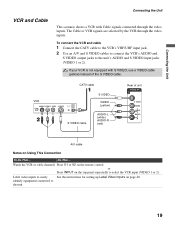
... equipped with Cable signals connected through the video inputs. VCR CATV cable S VIDEO cable S VIDEO VIDEO (yellow) AUDIO-L (white) AUDIO-R (red) Rear of the S VIDEO cable. Do This ... or Press INPUT on Using This Connection To Do This ... Label video inputs to easily See the instructions for setting up Label Video Inputs on the remote control. Watch the VCR or cable channels Press V1 or V2 on page 40. identify equipment connected to the unit's AUDIO and S VIDEO input jacks (VIDEO 1 or 2). The Cable or VCR signals are...
... equipped with Cable signals connected through the video inputs. VCR CATV cable S VIDEO cable S VIDEO VIDEO (yellow) AUDIO-L (white) AUDIO-R (red) Rear of the S VIDEO cable. Do This ... or Press INPUT on Using This Connection To Do This ... Label video inputs to easily See the instructions for setting up Label Video Inputs on the remote control. Watch the VCR or cable channels Press V1 or V2 on page 40. identify equipment connected to the unit's AUDIO and S VIDEO input jacks (VIDEO 1 or 2). The Cable or VCR signals are...

Operating Instructions
Page 21
Press V3 on page 40. See the instructions for setting up Label Video Inputs on the remote control. or Press INPUT on Using This Connection To Do This ... Connecting the Unit 21 Connecting the Unit Notes on the top panel repeatedly to the unit Do This ... Watch the HD equipment Label video inputs to easily identify equipment connected to select the HD equipment input (Video 3).
Press V3 on page 40. See the instructions for setting up Label Video Inputs on the remote control. or Press INPUT on Using This Connection To Do This ... Connecting the Unit 21 Connecting the Unit Notes on the top panel repeatedly to the unit Do This ... Watch the HD equipment Label video inputs to easily identify equipment connected to select the HD equipment input (Video 3).
Operating Instructions
Page 23
... Using This Connection To Do This ... If your DVD player is not equipped with S VIDEO and audio connectors If your DVD player does not have component video (YPBPR) jacks, or the component video inputs are already connected to the unit's AUDIO input jacks (VIDEO 1 or 2). Watch the DVD player Label video inputs to easily identify equipment connected to select the DVD player input (Video 3). or Press INPUT on page 40. See the instructions for setting up Label Video Inputs on the top panel...
... Using This Connection To Do This ... If your DVD player is not equipped with S VIDEO and audio connectors If your DVD player does not have component video (YPBPR) jacks, or the component video inputs are already connected to the unit's AUDIO input jacks (VIDEO 1 or 2). Watch the DVD player Label video inputs to easily identify equipment connected to select the DVD player input (Video 3). or Press INPUT on page 40. See the instructions for setting up Label Video Inputs on the top panel...

Operating Instructions
Page 24
... instructions for setting up Label Video Inputs on Using This Connection To Do This ... HDMI-Equipped Device Rear of unit IN 4 AUDIO IN RL HDMI cable Notes on page 40. 24 Press V4 on the rear panel. Do not connect a PC to select the HDMI-equipped device input (Video 4). Use the PC IN (RGB) connector instead when connecting a PC. or Press INPUT on the top panel repeatedly to the unit's HDMI input. HDMI cables transmit both audio...
... instructions for setting up Label Video Inputs on Using This Connection To Do This ... HDMI-Equipped Device Rear of unit IN 4 AUDIO IN RL HDMI cable Notes on page 40. 24 Press V4 on the rear panel. Do not connect a PC to select the HDMI-equipped device input (Video 4). Use the PC IN (RGB) connector instead when connecting a PC. or Press INPUT on the top panel repeatedly to the unit's HDMI input. HDMI cables transmit both audio...

Operating Instructions
Page 25
... Label video inputs to easily identify equipment connected to HDMI adapter or cable is used. Use the PC IN (RGB) connector instead when connecting a PC. 2 Use an Audio cable to connect the device's AUDIO output jacks to the unit's AUDIO input jacks on the remote control. Press V4 on the rear panel. Rear of unit IN 4 AUDIO IN RL Audio cable AUDIO-R (red) AUDIO-L (white) DVI to select the DVI-HDTV-equipped device input (Video 4). See the instructions for setting up Label Video Inputs on Using This Connection...
... Label video inputs to easily identify equipment connected to HDMI adapter or cable is used. Use the PC IN (RGB) connector instead when connecting a PC. 2 Use an Audio cable to connect the device's AUDIO output jacks to the unit's AUDIO input jacks on the remote control. Press V4 on the rear panel. Rear of unit IN 4 AUDIO IN RL Audio cable AUDIO-R (red) AUDIO-L (white) DVI to select the DVI-HDTV-equipped device input (Video 4). See the instructions for setting up Label Video Inputs on Using This Connection...

Operating Instructions
Page 26
... cable (analog RGB, supplied) Audio output terminal To D-Sub output terminal Notes on , press the power button again. z If the picture is recommended to the computer before connecting the supplied HD15-HD15 cable. It is noisy, flickering or not clear, adjust the Phase and Pitch in red. Watch the PC Label video inputs to easily identify equipment connected to VIDEO 5, the PC enters standby mode and the STANDBY LED lights in the PC Screen settings...
... cable (analog RGB, supplied) Audio output terminal To D-Sub output terminal Notes on , press the power button again. z If the picture is recommended to the computer before connecting the supplied HD15-HD15 cable. It is noisy, flickering or not clear, adjust the Phase and Pitch in red. Watch the PC Label video inputs to easily identify equipment connected to VIDEO 5, the PC enters standby mode and the STANDBY LED lights in the PC Screen settings...

Operating Instructions
Page 27
... or video game equipment AUDIO and S VIDEO output jacks to the unit's AUDIO and S VIDEO input jacks (VIDEO 1 or 2) on the rear of unit VIDEO IN 2 or S VIDEO S VIDEO VIDEO L (MONO) AUDIO R VIDEO (yellow) AUDIO-L (white) AUDIO-R (red) To S VIDEO jack To A/V output jack S VIDEO cable A/V cable Notes on the top panel repeatedly to the unit Do This ... If your unit's rear A/V input jacks. Press V1 or V2 on page 40. 27 See the instructions for setting up Label Video Inputs on the remote control...
... or video game equipment AUDIO and S VIDEO output jacks to the unit's AUDIO and S VIDEO input jacks (VIDEO 1 or 2) on the rear of unit VIDEO IN 2 or S VIDEO S VIDEO VIDEO L (MONO) AUDIO R VIDEO (yellow) AUDIO-L (white) AUDIO-R (red) To S VIDEO jack To A/V output jack S VIDEO cable A/V cable Notes on the top panel repeatedly to the unit Do This ... If your unit's rear A/V input jacks. Press V1 or V2 on page 40. 27 See the instructions for setting up Label Video Inputs on the remote control...

Operating Instructions
Page 28
... select the external equipment connected to display the current Video Input number and Wide Mode settings. Press to cycle through the power saving modes: Off, Low, High, Picture Off. The current program appears in freeze. Press repeatedly to adjust the volume. See "Using the Settings" on page 33. Press again or press VOL + to write down information such as a reference when operating the unit. See "Selecting Sound Options...
... select the external equipment connected to display the current Video Input number and Wide Mode settings. Press to cycle through the power saving modes: Off, Low, High, Picture Off. The current program appears in freeze. Press repeatedly to adjust the volume. See "Using the Settings" on page 33. Press again or press VOL + to write down information such as a reference when operating the unit. See "Selecting Sound Options...

Operating Instructions
Page 38
... Center: Vertical Size: Reset: Normal 0 0 0 0 Video 5 Select : Enter: Back: Exit: MENU You can change the settings for the PC input while the unit is displaying the PC screen. The PC Input Screen setting includes the following options: Option Wide Mode Auto Adjust Phase Pitch Horizontal Center Vertical Center Reset Description Normal Select to adjust the horizontal position of the picture. Note that Auto Adjust may not work well with certain input signals. Clear...
... Center: Vertical Size: Reset: Normal 0 0 0 0 Video 5 Select : Enter: Back: Exit: MENU You can change the settings for the PC input while the unit is displaying the PC screen. The PC Input Screen setting includes the following options: Option Wide Mode Auto Adjust Phase Pitch Horizontal Center Vertical Center Reset Description Normal Select to adjust the horizontal position of the picture. Note that Auto Adjust may not work well with certain input signals. Clear...

Operating Instructions
Page 42
... lead cables as interference may occur. No picture from other connecting cords. picture is too bright/Color is not ❑ Adjust the Picture Mode options in front of the unit or at the remote control sensor of 30 cm (11 7/8 inches) between the video equipment and the unit. ❑ Press V1 to lock in the Wide Screen Mode selected with remote control operation; Audio noise. ❑ Keep the set -top box/VCR antenna cable away...
... lead cables as interference may occur. No picture from other connecting cords. picture is too bright/Color is not ❑ Adjust the Picture Mode options in front of the unit or at the remote control sensor of 30 cm (11 7/8 inches) between the video equipment and the unit. ❑ Press V1 to lock in the Wide Screen Mode selected with remote control operation; Audio noise. ❑ Keep the set -top box/VCR antenna cable away...
Operating Instructions
Page 44
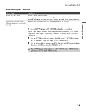
... and specifications are subject to change without stand) 25 kg (55 lb. 2 oz.) Supplied accessories: Remote control RM-YA004 (1) Size AA batteries (2) AC power cord (1) HD15-HD15 cable (1) Support belt (1), securing screw (1) and wood screw (1) Operating Instructions (1) Quick Setup Guide (1) Leaflet (Installing the Wall-Mount Bracket, KLV-32U100M only) (1) Warranty Card (1) Optional accessories: Headphones plug adaptor Connecting cables Wall-Mount Bracket SU-WL31 (KLV-32U100M) SU-WL51 (KLV-40U100M) Select the desired mounting angle from 0, 5, 10 or 15 degrees for these models. Optional...
... and specifications are subject to change without stand) 25 kg (55 lb. 2 oz.) Supplied accessories: Remote control RM-YA004 (1) Size AA batteries (2) AC power cord (1) HD15-HD15 cable (1) Support belt (1), securing screw (1) and wood screw (1) Operating Instructions (1) Quick Setup Guide (1) Leaflet (Installing the Wall-Mount Bracket, KLV-32U100M only) (1) Warranty Card (1) Optional accessories: Headphones plug adaptor Connecting cables Wall-Mount Bracket SU-WL31 (KLV-32U100M) SU-WL51 (KLV-40U100M) Select the desired mounting angle from 0, 5, 10 or 15 degrees for these models. Optional...

Operating Instructions
Page 45
..., 34 PICTURE button 28 Picture Mode 33, 34 Picture Mode Reset 33, 34 Pitch 38 POWER button 13, 28 POWER LED 14 Power Saving 30, 41 POWER SAVING button 28 R Reset 38 S S VIDEO jack 15 Settings Picture 32, 33 Screen 32, 36 Setup 32, 40 Sound 32, 35 Sharpness 33 Sleep 31 SLEEP button 28 Sleep Timer 40 SOUND button 28 Sound Mode 35 Sound Mode Reset 35 STANDBY LED 14 Support Belt 11 T, U Treble 35 Troubleshooting 42 turning on/off the unit 13 V Vertical Center 37, 38 Vertical Size 37 VIDEO/AUDIO...
..., 34 PICTURE button 28 Picture Mode 33, 34 Picture Mode Reset 33, 34 Pitch 38 POWER button 13, 28 POWER LED 14 Power Saving 30, 41 POWER SAVING button 28 R Reset 38 S S VIDEO jack 15 Settings Picture 32, 33 Screen 32, 36 Setup 32, 40 Sound 32, 35 Sharpness 33 Sleep 31 SLEEP button 28 Sleep Timer 40 SOUND button 28 Sound Mode 35 Sound Mode Reset 35 STANDBY LED 14 Support Belt 11 T, U Treble 35 Troubleshooting 42 turning on/off the unit 13 V Vertical Center 37, 38 Vertical Size 37 VIDEO/AUDIO...


