Operating Instructions
Page 3
... the limits for a Class B digital device, pursuant to Part 15 of Sony Corporation. All Rights Reserved. These limits are trademarks of the subwoofer. "BRAVIA" is a trademark of the FCC Rules. This system incorporates Dolby* Digital and Pro Logic Surround and the DTS** Digital Surround System. * Manufactured under U.S. WARNING This equipment has been tested and found...
... the limits for a Class B digital device, pursuant to Part 15 of Sony Corporation. All Rights Reserved. These limits are trademarks of the subwoofer. "BRAVIA" is a trademark of the FCC Rules. This system incorporates Dolby* Digital and Pro Logic Surround and the DTS** Digital Surround System. * Manufactured under U.S. WARNING This equipment has been tested and found...
Operating Instructions
Page 4
... to that the operating voltage is indicated on again after 15 to the wall outlet, even if the system itself ; Turn off the TV set, then turn it to be observed on the subwoofer, as alcohol or benzine. To disconnect the AC power cord (mains lead), grasp the plug itself has ...from the TV set . If color irregularity is observed... Place the system further away from the wall socket immediately in a place subject to turn off . • Install this system so that the power cord can be sure to your nearest Sony dealer. 4US If you continuously use any type of safety and will...
... to that the operating voltage is indicated on again after 15 to the wall outlet, even if the system itself ; Turn off the TV set, then turn it to be observed on the subwoofer, as alcohol or benzine. To disconnect the AC power cord (mains lead), grasp the plug itself has ...from the TV set . If color irregularity is observed... Place the system further away from the wall socket immediately in a place subject to turn off . • Install this system so that the power cord can be sure to your nearest Sony dealer. 4US If you continuously use any type of safety and will...
Operating Instructions
Page 7
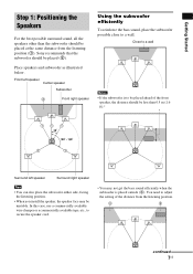
... the distance should be placed (2). You need to secure the speaker cord. • You may be unstable. Place speakers and subwoofer as illustrated below. Getting Started Step 1: Positioning the Speakers For the best possible surround sound, all the speakers other than 0.5 ...left speaker Center speaker Subwoofer 2 Front right speaker Using the subwoofer efficiently To reinforce the bass sound, place the subwoofer possible close to be placed ahead of the distance from the listening position (1). Sony recommends that the subwoofer should be less than the subwoofer should be placed at...
... the distance should be placed (2). You need to secure the speaker cord. • You may be unstable. Place speakers and subwoofer as illustrated below. Getting Started Step 1: Positioning the Speakers For the best possible surround sound, all the speakers other than 0.5 ...left speaker Center speaker Subwoofer 2 Front right speaker Using the subwoofer efficiently To reinforce the bass sound, place the subwoofer possible close to be placed ahead of the distance from the listening position (1). Sony recommends that the subwoofer should be less than the subwoofer should be placed at...
Operating Instructions
Page 8
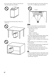
.... • Do not place the speakers in a cabinet, etc. • Do not place objects on the top of the subwoofer where the speaker unit is installed. • Do not place the subwoofer back of the obstruction, such as alcohol or benzine. • Image distortion on the TV screen may occur depending on... - Subject to direct sunlight • Use caution when placing the speakers and/or speaker stands (not supplied) that you change the positions of the speakers, Sony recommends that are : - In this case, place the subwoofer away from the TV.
.... • Do not place the speakers in a cabinet, etc. • Do not place objects on the top of the subwoofer where the speaker unit is installed. • Do not place the subwoofer back of the obstruction, such as alcohol or benzine. • Image distortion on the TV screen may occur depending on... - Subject to direct sunlight • Use caution when placing the speakers and/or speaker stands (not supplied) that you change the positions of the speakers, Sony recommends that are : - In this case, place the subwoofer away from the TV.
Operating Instructions
Page 9
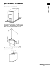
When lifting, hold the bottom of the subwoofer when lifting it. Getting Started Notes on handling the subwoofer • Place a soft cloth under the subwoofer when you lay the subwoofer down for connection. • Do not place your hand into the slit of the subwoofer. Speaker unit continued 9US Slits • Do not push the top of the subwoofer where the speaker unit is installed. The speaker driver may be damaged.
When lifting, hold the bottom of the subwoofer when lifting it. Getting Started Notes on handling the subwoofer • Place a soft cloth under the subwoofer when you lay the subwoofer down for connection. • Do not place your hand into the slit of the subwoofer. Speaker unit continued 9US Slits • Do not push the top of the subwoofer where the speaker unit is installed. The speaker driver may be damaged.
Operating Instructions
Page 15
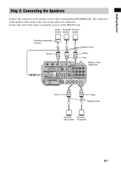
Connect the cord of the subwoofer CENTER FRONT R FRONT L SUR R SUR L Gray Blue Speaker cords Surround Surround right speaker left speaker 15US Center Front right Front left speaker speaker speaker Remote ...
Connect the cord of the subwoofer CENTER FRONT R FRONT L SUR R SUR L Gray Blue Speaker cords Surround Surround right speaker left speaker 15US Center Front right Front left speaker speaker speaker Remote ...
Operating Instructions
Page 16
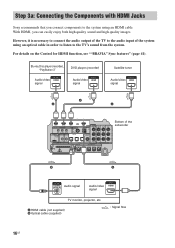
..., see ""BRAVIA" Sync features" (page 41). A HDMI cable (not supplied) B Optical cable (supplied) : Signal flow 16US However, it is necessary to connect the audio output of the TV to the TV's sound from the system. Step 3a: Connecting the Components with HDMI Jacks Sony recommends that ...you can easily enjoy both high quality sound and high quality images. With HDMI, you connect components to the system using an optical cable in order to listen to the audio input of the subwoofer CENTER FRONT R FRONT L SUR R SUR...
..., see ""BRAVIA" Sync features" (page 41). A HDMI cable (not supplied) B Optical cable (supplied) : Signal flow 16US However, it is necessary to connect the audio output of the TV to the TV's sound from the system. Step 3a: Connecting the Components with HDMI Jacks Sony recommends that ...you can easily enjoy both high quality sound and high quality images. With HDMI, you connect components to the system using an optical cable in order to listen to the audio input of the subwoofer CENTER FRONT R FRONT L SUR R SUR...
Operating Instructions
Page 18
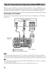
...components such as a TV or a projector to the MONITOR OUT jacks on the subwoofer. • Be sure to turn on the subwoofer when the video and audio of a playback component are being output to this subwoofer can be displayed on , neither video nor audio signal is equipped with a function...when you can reassign the analog audio input using the AUDIO IN ASSIGNABLE jacks. If the power supply of the system. Tips • You can choose the connecting combination of the subwoofer is not turned on a TV monitor, projector, etc. For details, see "Function for converting video signals. ...
...components such as a TV or a projector to the MONITOR OUT jacks on the subwoofer. • Be sure to turn on the subwoofer when the video and audio of a playback component are being output to this subwoofer can be displayed on , neither video nor audio signal is equipped with a function...when you can reassign the analog audio input using the AUDIO IN ASSIGNABLE jacks. If the power supply of the system. Tips • You can choose the connecting combination of the subwoofer is not turned on a TV monitor, projector, etc. For details, see "Function for converting video signals. ...
Operating Instructions
Page 19
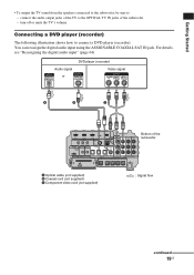
... IN DVD IN SAT IN DIGITAL SPEAKER R SAT IN AUDIO IN ASSIGNABLE ONLY FOR SS-IS15 PB/ CB PR/ CR COMPONENT VIDEO Bottom of the subwoofer. - You can reassign the digital audio input using the ASSIGNABLE COAXIAL SAT IN jack. Getting Started • To output the TV sound from the... speakers connected to the subwoofer, be sure to connect a DVD player (recorder). For details, see "Reassigning the digital audio input" (page 64). turn off or mute the TV's volume....
... IN DVD IN SAT IN DIGITAL SPEAKER R SAT IN AUDIO IN ASSIGNABLE ONLY FOR SS-IS15 PB/ CB PR/ CR COMPONENT VIDEO Bottom of the subwoofer. - You can reassign the digital audio input using the ASSIGNABLE COAXIAL SAT IN jack. Getting Started • To output the TV sound from the... speakers connected to the subwoofer, be sure to connect a DVD player (recorder). For details, see "Reassigning the digital audio input" (page 64). turn off or mute the TV's volume....
Operating Instructions
Page 20
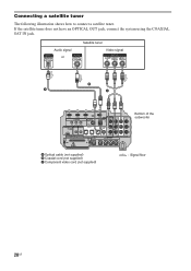
... IN DVD IN SAT IN DIGITAL SPEAKER R SAT IN AUDIO IN ASSIGNABLE ONLY FOR SS-IS15 PB/ CB PR/ CR COMPONENT VIDEO Bottom of the subwoofer CENTER FRONT R FRONT L SUR R SUR L A Optical cable (not supplied) B Coaxial cord (not supplied) C Component video cord (not supplied) : Signal flow 20US If the... satellite tuner does not have an OPTICAL OUT jack, connect the system using the COAXIAL SAT IN jack. Connecting a satellite tuner The following illustration shows how to connect a satellite tuner.
... IN DVD IN SAT IN DIGITAL SPEAKER R SAT IN AUDIO IN ASSIGNABLE ONLY FOR SS-IS15 PB/ CB PR/ CR COMPONENT VIDEO Bottom of the subwoofer CENTER FRONT R FRONT L SUR R SUR L A Optical cable (not supplied) B Coaxial cord (not supplied) C Component video cord (not supplied) : Signal flow 20US If the... satellite tuner does not have an OPTICAL OUT jack, connect the system using the COAXIAL SAT IN jack. Connecting a satellite tuner The following illustration shows how to connect a satellite tuner.
Operating Instructions
Page 21
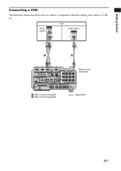
... IN DVD IN SAT IN DIGITAL SPEAKER R SAT IN AUDIO IN ASSIGNABLE ONLY FOR SS-IS15 PB/ CB PR/ CR COMPONENT VIDEO Bottom of the subwoofer CENTER FRONT R FRONT L SUR R SUR L A Audio cord (not supplied) B Video cord (not supplied) : Signal flow 21US Getting Started Connecting a VCR The following illustration shows how...
... IN DVD IN SAT IN DIGITAL SPEAKER R SAT IN AUDIO IN ASSIGNABLE ONLY FOR SS-IS15 PB/ CB PR/ CR COMPONENT VIDEO Bottom of the subwoofer CENTER FRONT R FRONT L SUR R SUR L A Audio cord (not supplied) B Video cord (not supplied) : Signal flow 21US Getting Started Connecting a VCR The following illustration shows how...
Operating Instructions
Page 22
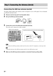
...loop antenna (aerial) for best AM broadcast sound. 4 Make sure the AM loop antenna (aerial) is designed to receive AM signals. Bottom of the subwoofer Insert the cords by pulling softly. 22US The cords can be connected to the AM antenna (aerial) terminals. Step 4: Connecting the Antenna (Aerial) Connecting... antenna (aerial) is connected firmly by pushing down the terminal clamp. Note • Do not place the AM loop antenna (aerial) near the system or other AV component, as noise may result. Do not dismantle or roll up the antenna (aerial). 1 Remove only the loop part from the...
...loop antenna (aerial) for best AM broadcast sound. 4 Make sure the AM loop antenna (aerial) is designed to receive AM signals. Bottom of the subwoofer Insert the cords by pulling softly. 22US The cords can be connected to the AM antenna (aerial) terminals. Step 4: Connecting the Antenna (Aerial) Connecting... antenna (aerial) is connected firmly by pushing down the terminal clamp. Note • Do not place the AM loop antenna (aerial) near the system or other AV component, as noise may result. Do not dismantle or roll up the antenna (aerial). 1 Remove only the loop part from the...
Operating Instructions
Page 23
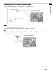
FM wire antenna (aerial) (supplied) FM 75 Ω COAXIAL jack Bottom of the subwoofer Outdoor FM antenna (aerial) BD IN DVD IN IR REMOTE SAT IN ANTENNA FM IR IN IR OUT1 IR OUT2 ...COAXIAL EZW-T100 TV IN DVD IN SAT IN DIGITAL SPEAKER SAT IN A ONLY F CENTER FRONT R FRONT L 23US Bottom of the subwoofer BD IN DVD IN IR REMOTE SAT IN ANTENNA FM IR IN IR OUT1 IR OUT2 DMPORT ECM-AC2 IR-R100 DC 5V 0.7A MAX...aerial) as possible. Tip • If you have poor FM reception, use a 75-ohm coaxial cable (not supplied) to connect the subwoofer to the FM 75 Ω COAXIAL jack.
FM wire antenna (aerial) (supplied) FM 75 Ω COAXIAL jack Bottom of the subwoofer Outdoor FM antenna (aerial) BD IN DVD IN IR REMOTE SAT IN ANTENNA FM IR IN IR OUT1 IR OUT2 ...COAXIAL EZW-T100 TV IN DVD IN SAT IN DIGITAL SPEAKER SAT IN A ONLY F CENTER FRONT R FRONT L 23US Bottom of the subwoofer BD IN DVD IN IR REMOTE SAT IN ANTENNA FM IR IN IR OUT1 IR OUT2 DMPORT ECM-AC2 IR-R100 DC 5V 0.7A MAX...aerial) as possible. Tip • If you have poor FM reception, use a 75-ohm coaxial cable (not supplied) to connect the subwoofer to the FM 75 Ω COAXIAL jack.
Operating Instructions
Page 24
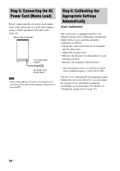
... room. The D.C.A.C. Step 5: Connecting the AC Power Cord (Mains Lead) Before connecting the AC power cord (mains lead) of the subwoofer to a wall outlet (mains), connect all the speakers to obtain proper sound balance in your preference. However, you to perform automatic calibration... as follows: • Check the connection between each speaker and the subwoofer. • Adjust the speaker level. • Measure the distance of each speaker to your listening position. • Measure the frequency ...
... room. The D.C.A.C. Step 5: Connecting the AC Power Cord (Mains Lead) Before connecting the AC power cord (mains lead) of the subwoofer to a wall outlet (mains), connect all the speakers to obtain proper sound balance in your preference. However, you to perform automatic calibration... as follows: • Check the connection between each speaker and the subwoofer. • Adjust the speaker level. • Measure the distance of each speaker to your listening position. • Measure the frequency ...
Operating Instructions
Page 25
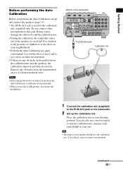
... any obstacles in a quiet environment to avoid the effect of noise and to avoid measurement error. Notes • If the muting function is on the subwoofer. 2 Set up and connect the speakers (page 15). • The ECM-AC2 jack is very loud. Place the calibration mic at the same height ...your listening position. You will turn off automatically. • When you perform the Auto Calibration, set up the calibration mic. Doing so may damage the subwoofer and the calibration mic. • During the calibration, the sound that the calibration mic remains at your ears. Bottom of the...
... any obstacles in a quiet environment to avoid the effect of noise and to avoid measurement error. Notes • If the muting function is on the subwoofer. 2 Set up and connect the speakers (page 15). • The ECM-AC2 jack is very loud. Place the calibration mic at the same height ...your listening position. You will turn off automatically. • When you perform the Auto Calibration, set up the calibration mic. Doing so may damage the subwoofer and the calibration mic. • During the calibration, the sound that the calibration mic remains at your ears. Bottom of the...
Operating Instructions
Page 26
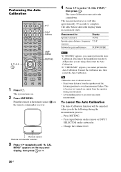
The system turns on the subwoofer. - response Subwoofer gain and distance SUBWOOFER Notes • ...the Auto Calibration. Performing the Auto Calibration C, X, x, c, TV ?/1 THEATER TV INPUT AV ?/1 ?/1 SYSTEM STANDBY TV BD DVD SAT SOUND FIELD VIDEO TUNER/BAND DMPORT BD/DVD TOP... MENU MENU F1 F2 JUMP PICTURE WIDE FAVORITE GUIDE 123 TONE 456 NIGHT MODE 789 CLEAR DISPLAY AMP MENU 0 ENTER TOOLS/ OPTIONS MUTING F TV VOL MASTER VOL G g ?/1 Input buttons AMP MENU MUTING f RETURN/EXIT MENU/HOME...
The system turns on the subwoofer. - response Subwoofer gain and distance SUBWOOFER Notes • ...the Auto Calibration. Performing the Auto Calibration C, X, x, c, TV ?/1 THEATER TV INPUT AV ?/1 ?/1 SYSTEM STANDBY TV BD DVD SAT SOUND FIELD VIDEO TUNER/BAND DMPORT BD/DVD TOP... MENU MENU F1 F2 JUMP PICTURE WIDE FAVORITE GUIDE 123 TONE 456 NIGHT MODE 789 CLEAR DISPLAY AMP MENU 0 ENTER TOOLS/ OPTIONS MUTING F TV VOL MASTER VOL G g ?/1 Input buttons AMP MENU MUTING f RETURN/EXIT MENU/HOME...
Operating Instructions
Page 27
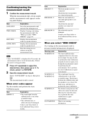
... and the speakers is no warning information. The distance and position of the acceptable range. • The calibration mic or subwoofer may be damaged. Getting Started Confirming/saving the measurement result 1 Confirm the measurement result. Either the surround left or surround ...Sony service facility. Set them away, and then try it again, even though the measurement cannot be performed in step 2, then press . continued 27US The measurement result is not connected. However, the noise level is displayed. Check that the surround speakers are not connected. The subwoofer...
... and the speakers is no warning information. The distance and position of the acceptable range. • The calibration mic or subwoofer may be damaged. Getting Started Confirming/saving the measurement result 1 Confirm the measurement result. Either the surround left or surround ...Sony service facility. Set them away, and then try it again, even though the measurement cannot be performed in step 2, then press . continued 27US The measurement result is not connected. However, the noise level is displayed. Check that the surround speakers are not connected. The subwoofer...
Operating Instructions
Page 28
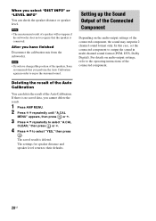
... select "DIST INFO" or "LEVEL INFO" You can delete the result of the connected component. For details on the audio output settings of the speakers, Sony recommends that the speaker is connected. The saved result is no saved data, you cannot delete the result. 1 Press AMP MENU. 2 Press x/X repeatedly until "A.CAL... level return to output the sound in order to select "YES," then press . Note • The measurement result of a speaker will not appear if the subwoofer does not recognize that you have finished Disconnect the calibration mic from the...
... select "DIST INFO" or "LEVEL INFO" You can delete the result of the connected component. For details on the audio output settings of the speakers, Sony recommends that the speaker is connected. The saved result is no saved data, you cannot delete the result. 1 Press AMP MENU. 2 Press x/X repeatedly until "A.CAL... level return to output the sound in order to select "YES," then press . Note • The measurement result of a speaker will not appear if the subwoofer does not recognize that you have finished Disconnect the calibration mic from the...
Operating Instructions
Page 29
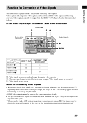
... no image may not be output from the HDMI OUT jack. In the video input/output conversion table of the subwoofer Input signals A BC Bottom of the subwoofer BD IN DVD IN IR REMOTE SAT IN ANTENNA FM TV OUT HDMI AM VIDEO VIDEO IN DVD IN SAT IN... IN B X COMPONENT a VIDEO IN C : Video signals are not output from a VCR, etc., are converted on the subwoofer and then output to off. 29US Getting Started Function for Conversion of Video Signals The subwoofer is output. X : Video signals are not up -converted and output through the video converter. Video signals and component...
... no image may not be output from the HDMI OUT jack. In the video input/output conversion table of the subwoofer Input signals A BC Bottom of the subwoofer BD IN DVD IN IR REMOTE SAT IN ANTENNA FM TV OUT HDMI AM VIDEO VIDEO IN DVD IN SAT IN... IN B X COMPONENT a VIDEO IN C : Video signals are not output from a VCR, etc., are converted on the subwoofer and then output to off. 29US Getting Started Function for Conversion of Video Signals The subwoofer is output. X : Video signals are not up -converted and output through the video converter. Video signals and component...
Operating Instructions
Page 30
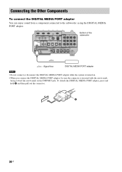
... IN DVD IN SAT IN DIGITAL SPEAKER R SAT IN AUDIO IN ASSIGNABLE ONLY FOR SS-IS15 PB/ CB PR/ CR COMPONENT VIDEO Bottom of the subwoofer CENTER FRONT R FRONT L SUR R SUR L : Signal flow DIGITAL MEDIA PORT adapter Notes • Do not connect or disconnect the DIGITAL MEDIA PORT ...adapter while the system is turned on. • When you connect the DIGITAL MEDIA PORT adapter, be sure the connector is inserted with the arrow mark facing toward the ...
... IN DVD IN SAT IN DIGITAL SPEAKER R SAT IN AUDIO IN ASSIGNABLE ONLY FOR SS-IS15 PB/ CB PR/ CR COMPONENT VIDEO Bottom of the subwoofer CENTER FRONT R FRONT L SUR R SUR L : Signal flow DIGITAL MEDIA PORT adapter Notes • Do not connect or disconnect the DIGITAL MEDIA PORT ...adapter while the system is turned on. • When you connect the DIGITAL MEDIA PORT adapter, be sure the connector is inserted with the arrow mark facing toward the ...


