Operating Instructions
Page 2
...off and on, the user is encouraged to try to rain or moisture. Install this system so that any changes or modification not expressly approved in this equipment. WARNING This equipment ...has been tested and found to operate this manual could void your Sony dealer regarding this equipment does cause harmful interference to the presence of the apparatus with the... be determined by one or more of the FCC Rules. Increase the separation between the equipment and receiver. - Do not install the appliance in a confined space, such as a bookcase or built-in...
...off and on, the user is encouraged to try to rain or moisture. Install this system so that any changes or modification not expressly approved in this equipment. WARNING This equipment ...has been tested and found to operate this manual could void your Sony dealer regarding this equipment does cause harmful interference to the presence of the apparatus with the... be determined by one or more of the FCC Rules. Increase the separation between the equipment and receiver. - Do not install the appliance in a confined space, such as a bookcase or built-in...
Operating Instructions
Page 3
...LLC. Center speaker SS-CNP890 - This receiver incorporates Dolby* Digital and Pro Logic Surround and the DTS** Digital Surround System. * Manufactured under U.S. All Rights Reserved. All rights reserved. "BRAVIA" and Sony Corporation. are trademarks of 3US DTS ... are trademarks of : • Receiver STR-K7200 • DVD player DVP-NS700H • Speaker system - This receiver incorporates High-Definition Multimedia Interface (HDMITM) technology. About This Manual • The instructions in this manual are for model HT-7200DH. Front speakers SS-MSP890 - Sub...
...LLC. Center speaker SS-CNP890 - This receiver incorporates Dolby* Digital and Pro Logic Surround and the DTS** Digital Surround System. * Manufactured under U.S. All Rights Reserved. All rights reserved. "BRAVIA" and Sony Corporation. are trademarks of 3US DTS ... are trademarks of : • Receiver STR-K7200 • DVD player DVP-NS700H • Speaker system - This receiver incorporates High-Definition Multimedia Interface (HDMITM) technology. About This Manual • The instructions in this manual are for model HT-7200DH. Front speakers SS-MSP890 - Sub...
Operating Instructions
Page 4
... speakers 14 2: Connecting the speakers 16 3: Connecting the TV 18 4a: Connecting the audio components ........19 4b: Connecting the video components ........20 5: Connecting the antennas 27 6: Preparing the receiver and the remote .....28 7: Calibrating the appropriate settings automatically (AUTO CALIBRATION 29 8: Adjusting the... DVD (One-Touch Play 67 Enjoying the TV sound from the speakers connected to the receiver (System Audio Control 68 Turning off the receiver with the TV (System Power Off 69 Other Operations Switching between digital and analog audio (INPUT MODE 70 Listening ...
... speakers 14 2: Connecting the speakers 16 3: Connecting the TV 18 4a: Connecting the audio components ........19 4b: Connecting the video components ........20 5: Connecting the antennas 27 6: Preparing the receiver and the remote .....28 7: Calibrating the appropriate settings automatically (AUTO CALIBRATION 29 8: Adjusting the... DVD (One-Touch Play 67 Enjoying the TV sound from the speakers connected to the receiver (System Audio Control 68 Turning off the receiver with the TV (System Power Off 69 Other Operations Switching between digital and analog audio (INPUT MODE 70 Listening ...
Operating Instructions
Page 5
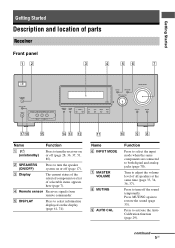
...OFF) Press to adjust the volume level of selectable items appears here (page 7). Turn to turn the speaker system on the display (page 61, 74). C Display The current status of the selected component or a list of all speakers at the same time (page 33, 34, 36, 37). Press to ...Press MUTING again to turn off (page 28, 36, 37, 51, 85). E DISPLAY Press to turn the receiver on or off the sound temporarily. Getting Started Getting Started Description and location of parts Receiver Front panel 12 3 4 56 7 ?/1 SPEAKERS (ON/OFF) AUTO CAL MIC PHONES VIDEO 2 IN/PORTABLE AV...
...OFF) Press to adjust the volume level of selectable items appears here (page 7). Turn to turn the speaker system on the display (page 61, 74). C Display The current status of the selected component or a list of all speakers at the same time (page 33, 34, 36, 37). Press to ...Press MUTING again to turn off (page 28, 36, 37, 51, 85). E DISPLAY Press to turn the receiver on or off the sound temporarily. Getting Started Getting Started Description and location of parts Receiver Front panel 12 3 4 56 7 ?/1 SPEAKERS (ON/OFF) AUTO CAL MIC PHONES VIDEO 2 IN/PORTABLE AV...

Operating Instructions
Page 7
.... Lights up when the Pro Logic II Movie or Music decoder is output from the SUB WOOFER jack. PLII" lights up when the receiver is set to output the center and surround channel signals. Lights up when INPUT MODE is decoding Dolby Digital signals. "; Lights up when the...you have made digital connections and that INPUT MODE is a digital signal being input through the OPTICAL jack (page 70). Lights up when using the receiver to "AUTO" and the source signal is set to tune in radio stations (page 52), etc. Getting Started About the indicators on presetting radio...
.... Lights up when the Pro Logic II Movie or Music decoder is output from the SUB WOOFER jack. PLII" lights up when the receiver is set to output the center and surround channel signals. Lights up when INPUT MODE is decoding Dolby Digital signals. "; Lights up when the...you have made digital connections and that INPUT MODE is a digital signal being input through the OPTICAL jack (page 70). Lights up when using the receiver to "AUTO" and the source signal is set to tune in radio stations (page 52), etc. Getting Started About the indicators on presetting radio...

Operating Instructions
Page 8
AUTO SW L C R SL SR 8US The boxes around the letters vary to show how the receiver downmixes the source sound. Front Left Front Right Center (monaural) Surround Left Surround Right Surround (monaural or the surround components obtained by Pro Logic processing) Example: Recording format (Front/ Surround): 3/2.1 Sound Field: A.F.D. The letters (L, C, R, etc.) indicate the channels being played back. Name M HDMI N Playback channel indicators L R C SL SR S Function Lights up when the receiver recognizes a component connected via an HDMI IN jack (page 21).
AUTO SW L C R SL SR 8US The boxes around the letters vary to show how the receiver downmixes the source sound. Front Left Front Right Center (monaural) Surround Left Surround Right Surround (monaural or the surround components obtained by Pro Logic processing) Example: Recording format (Front/ Surround): 3/2.1 Sound Field: A.F.D. The letters (L, C, R, etc.) indicate the channels being played back. Name M HDMI N Playback channel indicators L R C SL SR S Function Lights up when the receiver recognizes a component connected via an HDMI IN jack (page 21).
Operating Instructions
Page 9
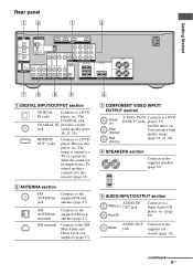
The image is output to this receiver (page 21). B ANTENNA section FM ANTENNA jack Connects to the jack supplied sub... VIDEO VIDEO VIDEO IN IN OUT IN OUT MONITOR AUDIO AUDIO AUDIO AUDIO IN IN OUT IN AUDIO OUT PB/ CB PR/ CR COMPONENT VIDEO SURROUND R L CENTER R SA-CD/CD/CD-R TV SAT DVD VIDEO 1 SUB WOOFER SPEAKERS FRONT L R 75 6 5...DVD IN/OUT* jacks player, TV, satellite tuner, etc. XM terminal Connects to the XM Mini-Tuner and Home Dock (not supplied) (page 57). 4 C COMPONENT VIDEO INPUT/ OUTPUT section Green (Y) Blue (PB/CB) Red (PR/CR) Y, PB/CB, PR/CR...
The image is output to this receiver (page 21). B ANTENNA section FM ANTENNA jack Connects to the jack supplied sub... VIDEO VIDEO VIDEO IN IN OUT IN OUT MONITOR AUDIO AUDIO AUDIO AUDIO IN IN OUT IN AUDIO OUT PB/ CB PR/ CR COMPONENT VIDEO SURROUND R L CENTER R SA-CD/CD/CD-R TV SAT DVD VIDEO 1 SUB WOOFER SPEAKERS FRONT L R 75 6 5...DVD IN/OUT* jacks player, TV, satellite tuner, etc. XM terminal Connects to the XM Mini-Tuner and Home Dock (not supplied) (page 57). 4 C COMPONENT VIDEO INPUT/ OUTPUT section Green (Y) Blue (PB/CB) Red (PR/CR) Y, PB/CB, PR/CR...
Operating Instructions
Page 10
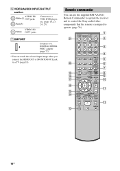
...SYSTEM STANDBY VIDEO 1 VIDEO 2 BD DVD SAT TV SA-CD/CD TUNER 1 2 3 w; Remote commander You can watch the selected input image when you connect the HDMI OUT or MONITOR OUT jack to a TV (page 18). CATEGORY MODE TUNING + m H M TV FM MODE X x qa qs 10US MOVIE MUSIC 1 4 7 >10 CLEAR DISPLAY THEATER... 23 DVD/BD MENU 56 AUTO CAL D.TUNING 89 D.SKIP MEMORY AMP MENU 0/10 ENTER TOOLS/ OPTIONS MUTING TV VOL MASTER VOL 4 5 6 7 8 9 q; O RETURN/EXIT MENU/HOME ...to operate the receiver and to control the Sony audio/video components that the remote is assigned to a VCR, DVD ...
...SYSTEM STANDBY VIDEO 1 VIDEO 2 BD DVD SAT TV SA-CD/CD TUNER 1 2 3 w; Remote commander You can watch the selected input image when you connect the HDMI OUT or MONITOR OUT jack to a TV (page 18). CATEGORY MODE TUNING + m H M TV FM MODE X x qa qs 10US MOVIE MUSIC 1 4 7 >10 CLEAR DISPLAY THEATER... 23 DVD/BD MENU 56 AUTO CAL D.TUNING 89 D.SKIP MEMORY AMP MENU 0/10 ENTER TOOLS/ OPTIONS MUTING TV VOL MASTER VOL 4 5 6 7 8 9 q; O RETURN/EXIT MENU/HOME ...to operate the receiver and to control the Sony audio/video components that the remote is assigned to a VCR, DVD ...

Operating Instructions
Page 11
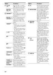
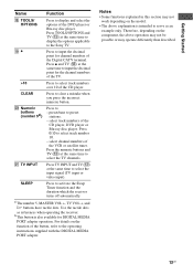
...only function if your TV is assigned to skip a disc when using the numeric buttons of the TV, VCR or satellite tuner. MOVIE MUSIC E THEATER F DVD/BD MENU AUTO CAL G D.TUNING D.SKIP H AMP MENU I ENTER MEMORY J MUTING Function Press to activate the Auto Calibration function. ...steps in tuner Name D 2CH A.F.D. Press to turn off the sound temporarily. Press to display the menu of the receiver. Note This button will turn off the receiver and other Sony components (SYSTEM STANDBY). Getting Started Name Function A TV ?/1 Press TV ?/1 and TV (M) at (on/standby) the same time...
...only function if your TV is assigned to skip a disc when using the numeric buttons of the TV, VCR or satellite tuner. MOVIE MUSIC E THEATER F DVD/BD MENU AUTO CAL G D.TUNING D.SKIP H AMP MENU I ENTER MEMORY J MUTING Function Press to activate the Auto Calibration function. ...steps in tuner Name D 2CH A.F.D. Press to turn off the sound temporarily. Press to display the menu of the receiver. Note This button will turn off the receiver and other Sony components (SYSTEM STANDBY). Getting Started Name Function A TV ?/1 Press TV ?/1 and TV (M) at (on/standby) the same time...
Operating Instructions
Page 12
... disc player. Press TV CH +/- Name Function M TV Press TV and the button with components in the forward/ reverse direction of the VCR, CD player, DVD player or Blu-ray disc player. Press MENU/HOME and TV (M) at the same time to return to skip a track of the TV. ... disc player. preset channels of the VCR, CD player or Bluray disc player. CATEGORY Press to display TV's information on the TV screen of the receiver, VCR, satellite tuner, CD player, DVD player or Bluray disc player. O RETURN/ EXIT O Press to select the settings. P V/v/B/b After pressing DVD/BD MENU ...
... disc player. Press TV CH +/- Name Function M TV Press TV and the button with components in the forward/ reverse direction of the VCR, CD player, DVD player or Blu-ray disc player. Press MENU/HOME and TV (M) at the same time to return to skip a track of the TV. ... disc player. preset channels of the VCR, CD player or Bluray disc player. CATEGORY Press to display TV's information on the TV screen of the receiver, VCR, satellite tuner, CD player, DVD player or Bluray disc player. O RETURN/ EXIT O Press to select the settings. P V/v/B/b After pressing DVD/BD MENU ...
Operating Instructions
Page 13
Press TV INPUT and TV (M) at the same time to display the options applicable to the Sony TV. Therefore, depending on the component, the above explanation is also available for the channel numbers of the TV. >10 Press to select track numbers over 10 of the button, ...- Press 0/10 to - a)The number 5, MASTER VOL +, TV VOL +, and H buttons have tactile dots. b)This button is intended to serve as references when operating the receiver. Press z and TV (M) at the same time to select the TV channels. select track numbers of the VCR or satellite tuner. Press the numeric buttons...
Press TV INPUT and TV (M) at the same time to display the options applicable to the Sony TV. Therefore, depending on the component, the above explanation is also available for the channel numbers of the TV. >10 Press to select track numbers over 10 of the button, ...- Press 0/10 to - a)The number 5, MASTER VOL +, TV VOL +, and H buttons have tactile dots. b)This button is intended to serve as references when operating the receiver. Press z and TV (M) at the same time to select the TV channels. select track numbers of the VCR or satellite tuner. Press the numeric buttons...
Operating Instructions
Page 14
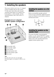
... enjoy theater-like multi channel surround sound requires five speakers (two front speakers, a center speaker, and two surround speakers) and a sub woofer (5.1 channel). Example of a 5.1 channel speaker system configuration Installing the speakers on the speaker stand For greater flexibility in positioning the speakers, use a 5.1 channel system (5 speakers... attach the supplied foot pads to the operating instructions supplied with the speaker stand. 1: Installing the speakers This receiver allows you to use the optional WS-FV11 speaker stand (available only in the illustration below.
... enjoy theater-like multi channel surround sound requires five speakers (two front speakers, a center speaker, and two surround speakers) and a sub woofer (5.1 channel). Example of a 5.1 channel speaker system configuration Installing the speakers on the speaker stand For greater flexibility in positioning the speakers, use a 5.1 channel system (5 speakers... attach the supplied foot pads to the operating instructions supplied with the speaker stand. 1: Installing the speakers This receiver allows you to use the optional WS-FV11 speaker stand (available only in the illustration below.
Operating Instructions
Page 19
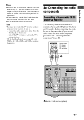
...: Connecting the audio components Connecting a Super Audio CD/CD player/CD recorder The following illustration shows how to connect a Super Audio CD player, CD player or CD recorder. Tips • To output the sound of the TV from the speakers connected to the receiver, be sure to ... are being output to a TV via the receiver. Unless the power is turned on the receiver when the video and audio signals of the receiver. - Before connecting the cords, be sure to "4b: Connecting the video components" (page 20). After connecting your audio component, proceed to - turn on , neither video...
...: Connecting the audio components Connecting a Super Audio CD/CD player/CD recorder The following illustration shows how to connect a Super Audio CD player, CD player or CD recorder. Tips • To output the sound of the TV from the speakers connected to the receiver, be sure to ... are being output to a TV via the receiver. Unless the power is turned on the receiver when the video and audio signals of the receiver. - Before connecting the cords, be sure to "4b: Connecting the video components" (page 20). After connecting your audio component, proceed to - turn on , neither video...
Operating Instructions
Page 20
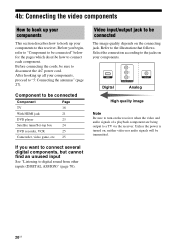
...connection according to a TV via the receiver. HDMI Digital Y PB/ CB PR/ CR COMPONENT VIDEO VIDEO Analog High quality image Note Be sure to turn on the receiver when the video and audio signals of a playback component are being output to the jacks on your components. Unless the power is turned on... the connecting jack. After hooking up your components to disconnect the AC power cord. Component to digital sound from other ...
...connection according to a TV via the receiver. HDMI Digital Y PB/ CB PR/ CR COMPONENT VIDEO VIDEO Analog High quality image Note Be sure to turn on the receiver when the video and audio signals of a playback component are being output to the jacks on your components. Unless the power is turned on... the connecting jack. After hooking up your components to disconnect the AC power cord. Component to digital sound from other ...

Operating Instructions
Page 21
...supports Dolby Digital, DTS, and Linear PCM. • This receiver supports xvYCC transmission. • This receiver supports the Control for HDMI" (page 64). For details, see "Control for HDMI function. Getting Started Connecting components with HDMI jacks HDMI is an interface which transmits video and audio... player Audio/video signals HDMI features • A digital audio signal transmitted by HDMI can be output from the speakers connected to this receiver. Blu-ray disc player Audio/video signals TV, projector, etc. Audio/video signals A A A A TV OPTICAL IN ANTENNA AM ...
...supports Dolby Digital, DTS, and Linear PCM. • This receiver supports xvYCC transmission. • This receiver supports the Control for HDMI" (page 64). For details, see "Control for HDMI function. Getting Started Connecting components with HDMI jacks HDMI is an interface which transmits video and audio... player Audio/video signals HDMI features • A digital audio signal transmitted by HDMI can be output from the speakers connected to this receiver. Blu-ray disc player Audio/video signals TV, projector, etc. Audio/video signals A A A A TV OPTICAL IN ANTENNA AM ...

Operating Instructions
Page 26
For details, see "Changing button assignments" (page 76). • You can also rename the VIDEO 1 input so that it can be displayed on the remote so that you can use the button to change the factory setting of the VIDEO 1 input button on the receiver's display. For details, see "Naming inputs" (page 73). 26US Notes • Be sure to control your DVD recorder.
For details, see "Changing button assignments" (page 76). • You can also rename the VIDEO 1 input so that it can be displayed on the remote so that you can use the button to change the factory setting of the VIDEO 1 input button on the receiver's display. For details, see "Naming inputs" (page 73). 26US Notes • Be sure to control your DVD recorder.

Operating Instructions
Page 27
... Y VIDEO VIDEO VIDEO VIDEO VIDEO IN IN OUT IN OUT MONITOR AUDIO AUDIO AUDIO AUDIO IN IN OUT IN AUDIO OUT PB/ CB PR/ CR COMPONENT VIDEO SURROUND R L CENTER R SA-CD/CD/CD-R TV SAT DVD VIDEO 1 SUB WOOFER SPEAKERS FRONT L R Notes • To prevent noise pickup, keep the... AM loop antenna away from the receiver and other components. • Be sure to disconnect the AC power cord. Before connecting the antennas, be sure to fully extend the FM wire antenna. • ...
... Y VIDEO VIDEO VIDEO VIDEO VIDEO IN IN OUT IN OUT MONITOR AUDIO AUDIO AUDIO AUDIO IN IN OUT IN AUDIO OUT PB/ CB PR/ CR COMPONENT VIDEO SURROUND R L CENTER R SA-CD/CD/CD-R TV SAT DVD VIDEO 1 SUB WOOFER SPEAKERS FRONT L R Notes • To prevent noise pickup, keep the... AM loop antenna away from the receiver and other components. • Be sure to disconnect the AC power cord. Before connecting the antennas, be sure to fully extend the FM wire antenna. • ...
Operating Instructions
Page 28
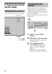
... on the display alternately. 3 Press MEMORY/ENTER. MOVIE MUSIC AUTO CAL MUTING 3 1 Press ?/1 to the initial settings. 28US 6: Preparing the receiver and the remote Connecting the AC power cord Connect the AC power cord to their factory defaults. All the settings you have changed or adjusted... are reset to turn off the receiver. 2 Hold down ?/1 for this operation. 1,2 FRONT L R To the wall outlet ?/1 SPEAKERS (ON/OFF) AUTO CAL MIC PHONES VIDEO 2 IN/PORTABLE AV IN...
... on the display alternately. 3 Press MEMORY/ENTER. MOVIE MUSIC AUTO CAL MUTING 3 1 Press ?/1 to the initial settings. 28US 6: Preparing the receiver and the remote Connecting the AC power cord Connect the AC power cord to their factory defaults. All the settings you have changed or adjusted... are reset to turn off the receiver. 2 Hold down ?/1 for this operation. 1,2 FRONT L R To the wall outlet ?/1 SPEAKERS (ON/OFF) AUTO CAL MIC PHONES VIDEO 2 IN/PORTABLE AV IN...
Operating Instructions
Page 29
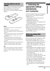
...16). • The AUTO CAL MIC jack is used for about 3 months. However, you replace the batteries, the remote buttons may damage the receiver and the microphone. • During calibration, the sound that comes out of the sound cannot be performed correctly. If this jack. Remove any ...obstacles in the path between each speaker and the receiver. • Adjusting the speaker level. • Measuring the distance of noise and to this happens, reassign the buttons again (page 76)....
...16). • The AUTO CAL MIC jack is used for about 3 months. However, you replace the batteries, the remote buttons may damage the receiver and the microphone. • During calibration, the sound that comes out of the sound cannot be performed correctly. If this jack. Remove any ...obstacles in the path between each speaker and the receiver. • Adjusting the speaker level. • Measuring the distance of noise and to this happens, reassign the buttons again (page 76)....
Operating Instructions
Page 31
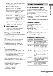
... Calibration. Tips • When Auto Calibration starts: - Press AUTO CAL again. Check the front speakers connection. "COMPLETE" appears on the receiver and perform Auto Calibration again (page 30). The speakers are detected. Only one error code. The table below . 5 Turn on the...is because test signals are more accurate measurement. • During the measurement process, the Auto Calibration function will appear on the receiver. - Measurement for Display Environment noise NOISE.CHK level Speaker connection MEASURE and SP DET. When you perform Auto Calibration again to...
... Calibration. Tips • When Auto Calibration starts: - Press AUTO CAL again. Check the front speakers connection. "COMPLETE" appears on the receiver and perform Auto Calibration again (page 30). The speakers are detected. Only one error code. The table below . 5 Turn on the...is because test signals are more accurate measurement. • During the measurement process, the Auto Calibration function will appear on the receiver. - Measurement for Display Environment noise NOISE.CHK level Speaker connection MEASURE and SP DET. When you perform Auto Calibration again to...


