
Operating Instructions
Page 1
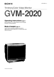
SON ©1991 by Sony Corporation Mode d'emploi page 12 Avant la mise en service de cet appareil, priere de lire attentivement ce mode d'emploi que Ion conservera pour toute reference ulterieure. SONY® Trinitron®Color Video Monitor 3-754-455-21 (1) Operating Instructions page 2 Before operating the unit, please read this manual thoroughly and retain it for future reference.
SON ©1991 by Sony Corporation Mode d'emploi page 12 Avant la mise en service de cet appareil, priere de lire attentivement ce mode d'emploi que Ion conservera pour toute reference ulterieure. SONY® Trinitron®Color Video Monitor 3-754-455-21 (1) Operating Instructions page 2 Before operating the unit, please read this manual thoroughly and retain it for future reference.
Operating Instructions
Page 3
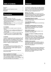
...Never pull the cord itself. Stubborn stains may not be fed through this unit, contact your authorized Sony dealer. Never use with a wide range of video equipment. Multiscan color monitor The monitor, which accepts 15 kHz to 36 kHz horizontal scanning frequencies and 50 Hz to 100 Hz vertical scanning...heat build-up. Compatible with RGB equipment using 64 colors The monitor allows reproduction of 8, 16 or 64 color for digital RGB input signals with the timing not indicated in the "Timing Chart" on page 10. The GVM-2020 is connected to equipment with the 16/64 or 8 COLOR ...
...Never pull the cord itself. Stubborn stains may not be fed through this unit, contact your authorized Sony dealer. Never use with a wide range of video equipment. Multiscan color monitor The monitor, which accepts 15 kHz to 36 kHz horizontal scanning frequencies and 50 Hz to 100 Hz vertical scanning...heat build-up. Compatible with RGB equipment using 64 colors The monitor allows reproduction of 8, 16 or 64 color for digital RGB input signals with the timing not indicated in the "Timing Chart" on page 10. The GVM-2020 is connected to equipment with the 16/64 or 8 COLOR ...
Operating Instructions
Page 5
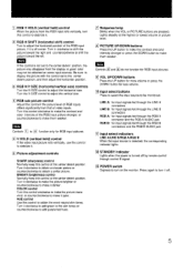
...the picture with the control set to the center detent position, the picture may disappear from the display or good color may not be monitored. RGB H/V SIZE (horizontal/vertical size) controls Turn the H-SIZE control to adjust the vertical size. Turn this control clockwise to make... control Normally keep this control at the center detent position. to Input select buttons Press to select the input source to be obtained on the monitor. Note If this control is selected, the corresponding indicator lights. I ] STANDBY indicator Lights when the power is off by remote control through ...
...the picture with the control set to the center detent position, the picture may disappear from the display or good color may not be monitored. RGB H/V SIZE (horizontal/vertical size) controls Turn the H-SIZE control to adjust the vertical size. Turn this control clockwise to make... control Normally keep this control at the center detent position. to Input select buttons Press to select the input source to be obtained on the monitor. Note If this control is selected, the corresponding indicator lights. I ] STANDBY indicator Lights when the power is off by remote control through ...
Operating Instructions
Page 6
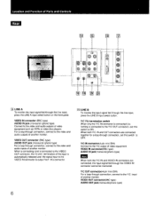
...)(phono type) 6 VIDEO IN connector (BNC type) AUDIO IN jack (monaural) (phono type) Connect to the video and audio outputs of another monitor. Y/C 750 termination switch When only the Y/C IN connector is connected to the Y/C OUT connector), set this switch to the Y/C output of video...select button on the front panel. Location and Function of Parts and Controls Rear 16 E c)I lo O eeee O 0 0 0 0 O 0 0, lE LINE A To monitor the input signal fed through this line input, press the LINE B input select button. VIDEO OUT connector (BNC type) AUDIO OUT jack (monaural) (phono type...
...)(phono type) 6 VIDEO IN connector (BNC type) AUDIO IN jack (monaural) (phono type) Connect to the video and audio outputs of another monitor. Y/C 750 termination switch When only the Y/C IN connector is connected to the Y/C OUT connector), set this switch to the Y/C output of video...select button on the front panel. Location and Function of Parts and Controls Rear 16 E c)I lo O eeee O 0 0 0 0 O 0 0, lE LINE A To monitor the input signal fed through this line input, press the LINE B input select button. VIDEO OUT connector (BNC type) AUDIO OUT jack (monaural) (phono type...
Operating Instructions
Page 7
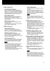
... for a loopthrough connection, as this unit is connected. RGB A connector (D-sub 9-pin) Connect to the RGB A/RGB B connectors. To monitor the input signal fed through the equipment connected. Notes • For video equipment with H/V composite sync and V sync, use only the composite... sync connection. • If horizontal sync signal has serration pulses*, the monitored picture may appear on G-signal is compatible with external equipment. Depress this switch to depress the selector (ON) when video equipment providing...
... for a loopthrough connection, as this unit is connected. RGB A connector (D-sub 9-pin) Connect to the RGB A/RGB B connectors. To monitor the input signal fed through the equipment connected. Notes • For video equipment with H/V composite sync and V sync, use only the composite... sync connection. • If horizontal sync signal has serration pulses*, the monitored picture may appear on G-signal is compatible with external equipment. Depress this switch to depress the selector (ON) when video equipment providing...


