
Operating Instructions
Page 1
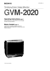
SON ©1991 by Sony Corporation Mode d'emploi page 12 Avant la mise en service de cet appareil, priere de lire attentivement ce mode d'emploi que Ion conservera pour toute reference ulterieure. SONY® Trinitron®Color Video Monitor 3-754-455-21 (1) Operating Instructions page 2 Before operating the unit, please read this manual thoroughly and retain it for future reference.
SON ©1991 by Sony Corporation Mode d'emploi page 12 Avant la mise en service de cet appareil, priere de lire attentivement ce mode d'emploi que Ion conservera pour toute reference ulterieure. SONY® Trinitron®Color Video Monitor 3-754-455-21 (1) Operating Instructions page 2 Before operating the unit, please read this manual thoroughly and retain it for future reference.
Operating Instructions
Page 2
... in this manual could void your Sony dealer regarding this equipment in a residential area is likely to cause interference in a commercial environment. This symbol is intended to alert the user to rain or moisture. DO NOT REMOVE COVER (OR BACK). REFER SERVICING TO QUALIFIED SERVICE PERSONNEL. English Owner's Record For the Customers in the space provided below. GVM-2020 Serial No. This...
... in this manual could void your Sony dealer regarding this equipment in a residential area is likely to cause interference in a commercial environment. This symbol is intended to alert the user to rain or moisture. DO NOT REMOVE COVER (OR BACK). REFER SERVICING TO QUALIFIED SERVICE PERSONNEL. English Owner's Record For the Customers in the space provided below. GVM-2020 Serial No. This...
Operating Instructions
Page 3
..., etc.) or near heat sources such as radiators or air ducts, or in a composite video signal, and also assuring the picture quality. The GVM-2020 is connected to direct sunlight, excessive dust, mechanical vibration or shock. Analog/digital RGB multi connector Analog and digital RGB input signals can be fed through the RGB A connector can be obtained when the GVM2020 is a high-resolution color video monitor for use strong solvents such as illustrated...
..., etc.) or near heat sources such as radiators or air ducts, or in a composite video signal, and also assuring the picture quality. The GVM-2020 is connected to direct sunlight, excessive dust, mechanical vibration or shock. Analog/digital RGB multi connector Analog and digital RGB input signals can be fed through the RGB A connector can be obtained when the GVM2020 is a high-resolution color video monitor for use strong solvents such as illustrated...
Operating Instructions
Page 5
... monitor. COLOR control Turn this control clockwise to make the contrast and color intensity stronger or press the DOWN button to turn on some input sources. RGB H/V SIZE (horizontal/vertical size) controls Turn the H-SIZE control to make them weaker. Note Controls i] to obtain a softer picture. Turn it clockwise to obtain a sharper picture or counterclockwise to X function only for input signals fed through control S signal. 1] POWER switch Depress to stabilize it the picture level of RGB inputs differs significantly from that of video inputs. I Picture adjustment...
... monitor. COLOR control Turn this control clockwise to make the contrast and color intensity stronger or press the DOWN button to turn on some input sources. RGB H/V SIZE (horizontal/vertical size) controls Turn the H-SIZE control to make them weaker. Note Controls i] to obtain a softer picture. Turn it clockwise to obtain a sharper picture or counterclockwise to X function only for input signals fed through control S signal. 1] POWER switch Depress to stabilize it the picture level of RGB inputs differs significantly from that of video inputs. I Picture adjustment...
Operating Instructions
Page 6
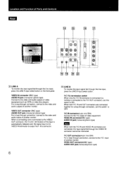
... A input select button on the front panel. Y/C OUT connector(4-pin mini-DIN) For a loop-through this connector. Location and Function of another monitor. When both the Y/C IN and VIDEO IN connectors are connected together for a loop-through connection, set this switch to the video and audio outputs of Parts and Controls Rear 16 E c)I lo O eeee O 0 0 0 0 O 0 0, lE LINE A To monitor the input signal fed through connection, connect to OFF. For a loop-through connection, connect...
... A input select button on the front panel. Y/C OUT connector(4-pin mini-DIN) For a loop-through this connector. Location and Function of another monitor. When both the Y/C IN and VIDEO IN connectors are connected together for a loop-through connection, set this switch to the video and audio outputs of Parts and Controls Rear 16 E c)I lo O eeee O 0 0 0 0 O 0 0, lE LINE A To monitor the input signal fed through connection, connect to OFF. For a loop-through connection, connect...
Operating Instructions
Page 7
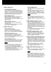
... space between horizontal-sync pulses SYNC ON GREEN selector When video equipment is connected to the CONTROL S output of the equipment. Keep the selector released for digital RGB equipment having either digital or analog RGB output. DIGITAL/ANALOG selector Depress this unit is compatible with the V SIZE control, a white stripe may occur when several monitors are ranged side by side for equipment having 16- The power on/off, input select, volume and picture settings can be...
... space between horizontal-sync pulses SYNC ON GREEN selector When video equipment is connected to the CONTROL S output of the equipment. Keep the selector released for digital RGB equipment having either digital or analog RGB output. DIGITAL/ANALOG selector Depress this unit is compatible with the V SIZE control, a white stripe may occur when several monitors are ranged side by side for equipment having 16- The power on/off, input select, volume and picture settings can be...
Operating Instructions
Page 8
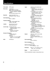
... and positive available, 0.3 Vp-p negative sync on green available AUDIO IN (LINE A/LINE B/RGB A/RGB B): phono jack (4) -5 dBs, high impedance CONTROL S: minijack (1) RGB A SELECT: minijack (1) Outputs VIDEO OUT (LINE A/LINE B): BNC connector (2) Y/C OUT: 4-pin mini-DIN (1) AUDIO OUT (LINE A/LINE B): phono jack (2) Power requirements 120 V AC, 50/60 Hz Power consumption 180 W Max. Specifications Color system NTSC system Picture tube Trinitron tube Approx. 54.5 cm (21 inches...
... and positive available, 0.3 Vp-p negative sync on green available AUDIO IN (LINE A/LINE B/RGB A/RGB B): phono jack (4) -5 dBs, high impedance CONTROL S: minijack (1) RGB A SELECT: minijack (1) Outputs VIDEO OUT (LINE A/LINE B): BNC connector (2) Y/C OUT: 4-pin mini-DIN (1) AUDIO OUT (LINE A/LINE B): phono jack (2) Power requirements 120 V AC, 50/60 Hz Power consumption 180 W Max. Specifications Color system NTSC system Picture tube Trinitron tube Approx. 54.5 cm (21 inches...
Operating Instructions
Page 9
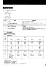
.... The signal from S-INPUT connector has priority over the one from LINE B VIDEO IN (BNC type) connector. Signal Pin No. 1 2 3 4 5 6 7 8 9 Sync level Analog GND (NC) R G B (NC) (NC) H/HV V HV:1Vp-p (Negative) H,V:TTL level (Positive or Negative) Digital 8-color GND (NC) R G B (NC) (NC) H/HV V TTL level (Positive or Negative) Digital 16-color GND (NC) R G B I (NC) H/HV V TTL level (H:Positive V:Positive) GND: Ground R: Red G: Green B: Blue (NC): No connection H: Horizontal sync V: Vertical sync HV: Composite sync I H/HV...
.... The signal from S-INPUT connector has priority over the one from LINE B VIDEO IN (BNC type) connector. Signal Pin No. 1 2 3 4 5 6 7 8 9 Sync level Analog GND (NC) R G B (NC) (NC) H/HV V HV:1Vp-p (Negative) H,V:TTL level (Positive or Negative) Digital 8-color GND (NC) R G B (NC) (NC) H/HV V TTL level (Positive or Negative) Digital 16-color GND (NC) R G B I (NC) H/HV V TTL level (H:Positive V:Positive) GND: Ground R: Red G: Green B: Blue (NC): No connection H: Horizontal sync V: Vertical sync HV: Composite sync I H/HV...
Warranty Card
Page 2
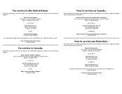
... avoir besoin : Appui technique Sony URL: www.sony.com/displays/support EMAIL: [email protected] ou écrivez à : Sony Electronics, Inc. 12451 Gateway Blvd. Ft. attn. For service in the United States: For your convenience, Sony of Canada Ltd. has established a group to supply you with technical support: Sony Technical Support URL: www.sony.com/displays/support EMAIL: [email protected]...
... avoir besoin : Appui technique Sony URL: www.sony.com/displays/support EMAIL: [email protected] ou écrivez à : Sony Electronics, Inc. 12451 Gateway Blvd. Ft. attn. For service in the United States: For your convenience, Sony of Canada Ltd. has established a group to supply you with technical support: Sony Technical Support URL: www.sony.com/displays/support EMAIL: [email protected]...


