Operating Instructions
Page 2
...electric shock to rain or moisture, does not operate normally, or has been dropped. Owner's record The model number is not designed as radiators, heat registers, stoves, or other . DSR-45 Serial No Important Safety Instructions • Read these instructions. • Keep these numbers whenever ... near any heat sources such as a portable. This symbol is inclined 30 degrees or more (i.e., if you call upon your Sony dealer regarding this apparatus during lightning storms or when unused for long periods of important operating and maintenance (servicing) instructions in the...
...electric shock to rain or moisture, does not operate normally, or has been dropped. Owner's record The model number is not designed as radiators, heat registers, stoves, or other . DSR-45 Serial No Important Safety Instructions • Read these instructions. • Keep these numbers whenever ... near any heat sources such as a portable. This symbol is inclined 30 degrees or more (i.e., if you call upon your Sony dealer regarding this apparatus during lightning storms or when unused for long periods of important operating and maintenance (servicing) instructions in the...
Operating Instructions
Page 3
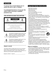
...interference, and (2) this manual could void your authority to radio communications. If this recorder with Part 15 of the FCC Rules. GB • Connect the equipment into an...owner. 3 (GB) English Caution Television programs, films, video tapes and other materials may call: Sony's Business Information Center (BIC) at 1-800686-SONY (7669) or Write to the provisions of the following two...to Part 15 of Conformity Trade Name: Model: Responsible Party: Address: Telephone Number: SONY DSR-45 Sony Electronics Inc. 680 Kinderkamack Road, Oradell, NJ 07649 USA 201-930-6972 This device ...
...interference, and (2) this manual could void your authority to radio communications. If this recorder with Part 15 of the FCC Rules. GB • Connect the equipment into an...owner. 3 (GB) English Caution Television programs, films, video tapes and other materials may call: Sony's Business Information Center (BIC) at 1-800686-SONY (7669) or Write to the provisions of the following two...to Part 15 of Conformity Trade Name: Model: Responsible Party: Address: Telephone Number: SONY DSR-45 Sony Electronics Inc. 680 Kinderkamack Road, Oradell, NJ 07649 USA 201-930-6972 This device ...
Operating Instructions
Page 9
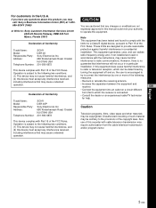
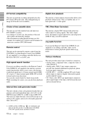
...video). Wide track pitch The recording track pitch is a digital videocassette recorder using 1/4-inch tape. High picture quality, high stability Video signals are encoded and compressed to one-fifth size before being recorded ...DSR-45/ 45P allows you check images easily. There are described below. Because the recording is based on page 101 (GB). The built-in color LCD monitor lets you to -noise ratio, thereby enhancing sound quality. High-quality PCM digital audio PCM recording makes for professional use. Equipped with virtually no deterioration of professional editing...
...video). Wide track pitch The recording track pitch is a digital videocassette recorder using 1/4-inch tape. High picture quality, high stability Video signals are encoded and compressed to one-fifth size before being recorded ...DSR-45/ 45P allows you check images easily. There are described below. Because the recording is based on page 101 (GB). The built-in color LCD monitor lets you to -noise ratio, thereby enhancing sound quality. High-quality PCM digital audio PCM recording makes for professional use. Equipped with virtually no deterioration of professional editing...
Operating Instructions
Page 10
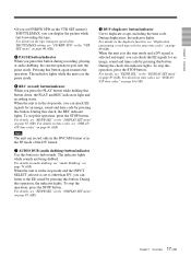
...unit can be adjusted. The video output level, chrominance signal output level, and setup level (DSR-45 only) can all be monitored at various playback speeds when in jog mode. video (IN/OUT) • ... Features Chapter 1 Overview DV format compatibility The unit can perform recording and playback in the DV-format (SP mode only). (Recording/playing an image in jog mode. You can also search frame...from the CONTROL S system Remote Control Unit (DSRM20, not supplied), or an editing controller that allows you to view color pictures at +1/3time speed and -1/3-time speed. Remote control...
...unit can be adjusted. The video output level, chrominance signal output level, and setup level (DSR-45 only) can all be monitored at various playback speeds when in jog mode. video (IN/OUT) • ... Features Chapter 1 Overview DV format compatibility The unit can perform recording and playback in the DV-format (SP mode only). (Recording/playing an image in jog mode. You can also search frame...from the CONTROL S system Remote Control Unit (DSRM20, not supplied), or an editing controller that allows you to view color pictures at +1/3time speed and -1/3-time speed. Remote control...
Operating Instructions
Page 17
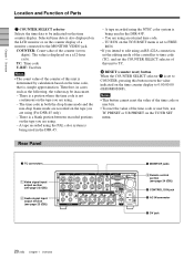
... SET menu" on page 85 (GB). For details, see "DSR-45/ 45P time codes" on the VTR SET menu to SHUTTLEMAX, you can record only in the DVCAM format or in the stop the operation, press... tape. For details on audio dubbing, see "FF/REW SPD" in the pause mode. 6 REC (record) button/indicator When you press the PLAY button while holding this button again resumes the operation. During this ... signal is set FF/REW SPD on page 63 (GB). 17 Chapter 1 Overview (GB) For details, see "DSR-45/ 45P time codes" on page 85 (GB). 8 DUP (duplicate) button/indicator Use to dub sounds. For details...
... SET menu" on page 85 (GB). For details, see "DSR-45/ 45P time codes" on the VTR SET menu to SHUTTLEMAX, you can record only in the DVCAM format or in the stop the operation, press... tape. For details on audio dubbing, see "FF/REW SPD" in the pause mode. 6 REC (record) button/indicator When you press the PLAY button while holding this button again resumes the operation. During this ... signal is set FF/REW SPD on page 63 (GB). 17 Chapter 1 Overview (GB) For details, see "DSR-45/ 45P time codes" on page 85 (GB). 8 DUP (duplicate) button/indicator Use to dub sounds. For details...
Operating Instructions
Page 20
...177;12-hour cycle. There is a blank portion between recorded portions on the tape you are using an RS-422A connection, set the editing mode of the controller to time code (TC), and ...Overview Location and Function of Parts 7 COUNTER SELECT selector Selects the time data to the MONITOR VIDEO jack. A tape recorded using the PAL color system is being used in cases such as the following, the value ...is a portion where the time code is displayed on the TC/UB SET menu. A tape recorded using (For DSR-45 only). - You are using the NTSC color system is set to COUNTER, pressing this unit...
...177;12-hour cycle. There is a blank portion between recorded portions on the tape you are using an RS-422A connection, set the editing mode of the controller to time code (TC), and ...Overview Location and Function of Parts 7 COUNTER SELECT selector Selects the time data to the MONITOR VIDEO jack. A tape recorded using the PAL color system is being used in cases such as the following, the value ...is a portion where the time code is displayed on the TC/UB SET menu. A tape recorded using (For DSR-45 only). - You are using the NTSC color system is set to COUNTER, pressing this unit...
Operating Instructions
Page 21
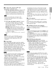
..., the time code is output during recording, dubbing, or capturing still pictures, all by means of the EE pictures output from the MONITOR VIDEO jack, sync and burst are delayed by several lines. For details on the superimposed data items, see "DSR-45/45P time codes" on the external ...exactly externally synchronized - Connect the input jack of the external device. When played back, the picture is in the standby mode, it consumes power. Recording: Either the time code generated by the setting of a device connected to a device equipped with a 6- pin DV jack, when you connect ...
..., the time code is output during recording, dubbing, or capturing still pictures, all by means of the EE pictures output from the MONITOR VIDEO jack, sync and burst are delayed by several lines. For details on the superimposed data items, see "DSR-45/45P time codes" on the external ...exactly externally synchronized - Connect the input jack of the external device. When played back, the picture is in the standby mode, it consumes power. Recording: Either the time code generated by the setting of a device connected to a device equipped with a 6- pin DV jack, when you connect ...
Operating Instructions
Page 22
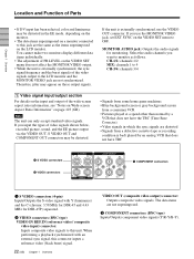
... synchronized with Y (luminance) and the C (chroma: 3.58 MHz for DSR-45 and 4.43 MHz for monitoring. MONITOR AUDIO jack: Outputs the audio signals for DSR-45P) separated. 2 VIDEO connectors (BNC-type) VIDEO IN REF.IN (reference video / composite video input) connector: Inputs composite video signals to 4 CH-3/4: channels 3/4 1 Video signal input/output section For details on the input and...
... synchronized with Y (luminance) and the C (chroma: 3.58 MHz for DSR-45 and 4.43 MHz for monitoring. MONITOR AUDIO jack: Outputs the audio signals for DSR-45P) separated. 2 VIDEO connectors (BNC-type) VIDEO IN REF.IN (reference video / composite video input) connector: Inputs composite video signals to 4 CH-3/4: channels 3/4 1 Video signal input/output section For details on the input and...
Operating Instructions
Page 24
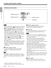
... L have an M / S switching function cannot be connected to this unit as a player, set the LANC mode on the recorder to M. Either this, the unit or the other device may not operate properly. •... used to control a consumer VCR 24 (GB) Chapter 1 Overview However, editing operations attempted in this case are not guaranteed. • For editing, if you also need to use the IF-FXE2 LANC Interface Box. 1...the LANC jack 3 to control the unit.) • Even when the DSR-45 plays back a PAL formatted tape (or the DSR-45P plays back an NTSC formatted tape), you can control the basic tape...
... L have an M / S switching function cannot be connected to this unit as a player, set the LANC mode on the recorder to M. Either this, the unit or the other device may not operate properly. •... used to control a consumer VCR 24 (GB) Chapter 1 Overview However, editing operations attempted in this case are not guaranteed. • For editing, if you also need to use the IF-FXE2 LANC Interface Box. 1...the LANC jack 3 to control the unit.) • Even when the DSR-45 plays back a PAL formatted tape (or the DSR-45P plays back an NTSC formatted tape), you can control the basic tape...
Operating Instructions
Page 28
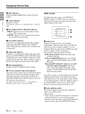
...Displays a caution. For details on the AUDIO SET menu. During playback, displays the recording format of channel 1 and 2 are displayed on the LCD monitor or on page 97 (GB). 8 PAL (DSR-45)/NTSC (DSR-45P) indicator DSR-45: Appears for five seconds when you play back an NTSC formatted tape. 9 DVCAM/...DV indicator In the EE or recording mode, displays the recording format selected in AUDIO MODE on cautions, see "Compatibility of ...
...Displays a caution. For details on the AUDIO SET menu. During playback, displays the recording format of channel 1 and 2 are displayed on the LCD monitor or on page 97 (GB). 8 PAL (DSR-45)/NTSC (DSR-45P) indicator DSR-45: Appears for five seconds when you play back an NTSC formatted tape. 9 DVCAM/...DV indicator In the EE or recording mode, displays the recording format selected in AUDIO MODE on cautions, see "Compatibility of ...
Operating Instructions
Page 32
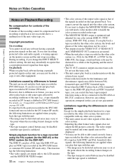
... the DSR-45P) The DSR-45 can play a PAL tape (the DSR-45P can also record and play an NTSC tape) recorded in the DVCAM format and one color system (DSR-45: NTSC system; Limitations regarding the differences in color systems Except for the simple playback function for a tape recorded in this unit. Copyright precautions On recording You cannot record any editing...
... the DSR-45P) The DSR-45 can play a PAL tape (the DSR-45P can also record and play an NTSC tape) recorded in the DVCAM format and one color system (DSR-45: NTSC system; Limitations regarding the differences in color systems Except for the simple playback function for a tape recorded in this unit. Copyright precautions On recording You cannot record any editing...
Operating Instructions
Page 33
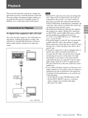
...signals. If these phenomena occur, perform one of an editing system, for Playback To digital video equipment with a DV jack The video and audio signals are transmitted to prevent malfunction resulting from...its power cord from noise, etc. Connections for dubbing, or as a stand-alone videocassette player. The signal flow is output from the DV jack of the device to this unit, which...the following: - Monitor DSR-45/45P (rear panel) i.LINK cable (DV cable) (not supplied) DV jack Notes • With the DV connection, data codes (recording date/ time, camera data) recorded on the source tape...
...signals. If these phenomena occur, perform one of an editing system, for Playback To digital video equipment with a DV jack The video and audio signals are transmitted to prevent malfunction resulting from...its power cord from noise, etc. Connections for dubbing, or as a stand-alone videocassette player. The signal flow is output from the DV jack of the device to this unit, which...the following: - Monitor DSR-45/45P (rear panel) i.LINK cable (DV cable) (not supplied) DV jack Notes • With the DV connection, data codes (recording date/ time, camera data) recorded on the source tape...
Operating Instructions
Page 34
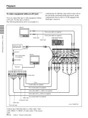
Monitor Phono jack cable (not supplied) Phono jack cable (not supplied) Audio input Video input DSR-45/45P (player) (rear panel) Reference video signal generator B.B.OUT B.B.OUT 75 Ω coaxial cable (not supplied) REF.VIDEO Monitor Recorder S-video input S-video cable (not supplied) 75 Ω coaxial cable (not supplied) Video cable (3BNC y 3BNC) (not supplied) Audio cable (XLR y XLR) (not supplied...
Monitor Phono jack cable (not supplied) Phono jack cable (not supplied) Audio input Video input DSR-45/45P (player) (rear panel) Reference video signal generator B.B.OUT B.B.OUT 75 Ω coaxial cable (not supplied) REF.VIDEO Monitor Recorder S-video input S-video cable (not supplied) 75 Ω coaxial cable (not supplied) Video cable (3BNC y 3BNC) (not supplied) Audio cable (XLR y XLR) (not supplied...
Operating Instructions
Page 40
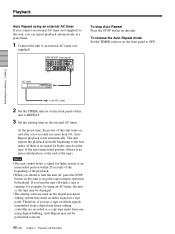
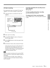
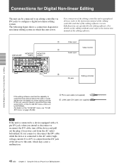
...8226; The editing software used on the digital non-linear editing system may be performed correctly. 40 (GB) Chapter 2 Playback and Recording Therefore, if you use a tape on which signals transmitted from a digital non-linear editing controller are recorded or a...on the front panel to REPEAT. 3 Set the starting time on this unit. Chapter 2 Playback and Recording AC timer to an AC outlet 2 Set the TIMER selector on the front panel of the playback. &#...unit off , press the STOP button on the external AC timer. DSR-45/45P (rear panel) To stop the tape transport operation beforehand.
...8226; The editing software used on the digital non-linear editing system may be performed correctly. 40 (GB) Chapter 2 Playback and Recording Therefore, if you use a tape on which signals transmitted from a digital non-linear editing controller are recorded or a...on the front panel to REPEAT. 3 Set the starting time on this unit. Chapter 2 Playback and Recording AC timer to an AC outlet 2 Set the TIMER selector on the front panel of the playback. &#...unit off , press the STOP button on the external AC timer. DSR-45/45P (rear panel) To stop the tape transport operation beforehand.
Operating Instructions
Page 41
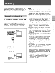
... where a signal is recorded in a different audio recording mode from the unit may be distorted. Monitor DSR-45/45P (rear panel) i.LINK cable (DV cable) (not supplied) DV jack Digital video equipment with a DV jack The video and audio signals are...recording date/ time, camera data) recorded on the monitor screen. Chapter 2 Playback and Recording Recording This section describes the connections, settings and operations necessary to perform recording on the digital video equipment connected. • If you connect the output connectors of this unit to the input connectors of a player...
... where a signal is recorded in a different audio recording mode from the unit may be distorted. Monitor DSR-45/45P (rear panel) i.LINK cable (DV cable) (not supplied) DV jack Digital video equipment with a DV jack The video and audio signals are...recording date/ time, camera data) recorded on the monitor screen. Chapter 2 Playback and Recording Recording This section describes the connections, settings and operations necessary to perform recording on the digital video equipment connected. • If you connect the output connectors of this unit to the input connectors of a player...

Operating Instructions
Page 42
Monitor Player S-video output Video output Audio output Component output Monitor Phono jack cable (not supplied) Audio input Video input DSR-45/45P (recorder) (rear panel) Phono jack cable (not supplied) S-video cable (not supplied) 75 Ω coaxial cable (not supplied) Audio cable (phono jack) (not supplied) Video cable (... 90 (GB). • If you connect the output connectors of audio output connectors on the player (see page on 23 (GB)). Chapter 2 Playback and Recording Recording To video equipment without a DV jack. Use this unit to a position where a signal is not currently...
Monitor Player S-video output Video output Audio output Component output Monitor Phono jack cable (not supplied) Audio input Video input DSR-45/45P (recorder) (rear panel) Phono jack cable (not supplied) S-video cable (not supplied) 75 Ω coaxial cable (not supplied) Audio cable (phono jack) (not supplied) Video cable (... 90 (GB). • If you connect the output connectors of audio output connectors on the player (see page on 23 (GB)). Chapter 2 Playback and Recording Recording To video equipment without a DV jack. Use this unit to a position where a signal is not currently...
Operating Instructions
Page 45
... example, by using an AC timer, the unit or the tape may be damaged. 45 Chapter 2 Playback and Recording (GB) Recording source (external tuner, etc.) DSR-45/45P (rear panel) VIDEO IN REF. IN AC timer If the tape ends before the recording source stops operation The tape stops. If you can start . To stop the tape...
... example, by using an AC timer, the unit or the tape may be damaged. 45 Chapter 2 Playback and Recording (GB) Recording source (external tuner, etc.) DSR-45/45P (rear panel) VIDEO IN REF. IN AC timer If the tape ends before the recording source stops operation The tape stops. If you can start . To stop the tape...
Operating Instructions
Page 48
... used has the capability to output the time code as well as the video or audio signals from the digital non-linear editing controller to this unit, and you intend to record the time code, set DV IN TC on the TC/UB SET menu of this ...non-linear editing system in an Editing System DV 2 Editing controller DV jack If the editing software used , refer to this unit, which may cause a malfunction. 48 (GB) Chapter 3 Using the Unit as a Player in which this unit to configure a digital non-linear editing system. DSR-45/45P MONITOR VIDEO MONITOR AUDIO 1 Video input Video monitor 1 ...
... used has the capability to output the time code as well as the video or audio signals from the digital non-linear editing controller to this unit, and you intend to record the time code, set DV IN TC on the TC/UB SET menu of this ...non-linear editing system in an Editing System DV 2 Editing controller DV jack If the editing software used , refer to this unit, which may cause a malfunction. 48 (GB) Chapter 3 Using the Unit as a Player in which this unit to configure a digital non-linear editing system. DSR-45/45P MONITOR VIDEO MONITOR AUDIO 1 Video input Video monitor 1 ...
Operating Instructions
Page 49
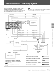
... other than five seconds. S VIDEO OUT 5 VIDEO OUT 1 COMPONENT OUT 1 DSR-45/45P (player) MONITOR VIDEO 3 MONITOR AUDIO 3 Video input Audio input S VIDEO IN VIDEO IN Y, R-Y, B-Y IN Source video monitor Chapter 3 Using the Unit as a Player in an Editing System (GB) Note The preroll time of the setting on the editing controller is required to be more than the DSR-45/ 45P, refer to the...
... other than five seconds. S VIDEO OUT 5 VIDEO OUT 1 COMPONENT OUT 1 DSR-45/45P (player) MONITOR VIDEO 3 MONITOR AUDIO 3 Video input Audio input S VIDEO IN VIDEO IN Y, R-Y, B-Y IN Source video monitor Chapter 3 Using the Unit as a Player in an Editing System (GB) Note The preroll time of the setting on the editing controller is required to be more than the DSR-45/ 45P, refer to the...
Operating Instructions
Page 50
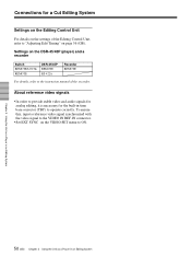
.... To ensure this, input a reference video signal synchronized with the video signal to the VIDEO IN REF.IN connector. • Set EXT SYNC on the DSR-45/45P (player) and a recorder Switch REMOTE/LOCAL REMOTE DSR-45/45P REMOTE RS-422A Recorder REMOTE For details, refer to ON. Chapter 3 Using the Unit as a Player in an Editing System 50 (GB) Chapter 3 Using...
.... To ensure this, input a reference video signal synchronized with the video signal to the VIDEO IN REF.IN connector. • Set EXT SYNC on the DSR-45/45P (player) and a recorder Switch REMOTE/LOCAL REMOTE DSR-45/45P REMOTE RS-422A Recorder REMOTE For details, refer to ON. Chapter 3 Using the Unit as a Player in an Editing System 50 (GB) Chapter 3 Using...


