
Operating Instructions
Page 121
... Approx. 130 g (5 oz) x Accessories • HR6 (size AA) Ni-MH batteries (DSC-W1: 2, DSC-W12: 4) • Battery case (DSC-W1: 1, DSC-W12: 2) • BC-CS2A/CS2B Ni-MH Battery charger (1) • Power cord (mains lead) (1) • USB cable (1) • A/V connecting cable (1) • Wrist strap (1) • "Memory Stick" (32 MB) (1) • CD-ROM (USB driver SPVD-012) (1) •...
... Approx. 130 g (5 oz) x Accessories • HR6 (size AA) Ni-MH batteries (DSC-W1: 2, DSC-W12: 4) • Battery case (DSC-W1: 1, DSC-W12: 2) • BC-CS2A/CS2B Ni-MH Battery charger (1) • Power cord (mains lead) (1) • USB cable (1) • A/V connecting cable (1) • Wrist strap (1) • "Memory Stick" (32 MB) (1) • CD-ROM (USB driver SPVD-012) (1) •...
Service Manual
Page 2
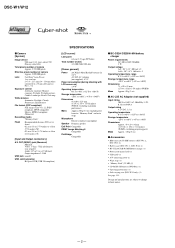
... cord (mains lead) (1) • USB cable (1) • A/V connecting cable (1) • Wrist strap (1) • "Memory Stick" (32 MB) (1) • CD-ROM (USB driver SPVD-012) (1) • Operating instructions (1) • Soft carrying case (DSC-W12 only) (1) See page 5-15. DSC-W1/W12 x Camera [System] Image device 9.04 mm (1/1.8 type) color CCD Primary color filter Total pixels number...
... cord (mains lead) (1) • USB cable (1) • A/V connecting cable (1) • Wrist strap (1) • "Memory Stick" (32 MB) (1) • CD-ROM (USB driver SPVD-012) (1) • Operating instructions (1) • Soft carrying case (DSC-W12 only) (1) See page 5-15. DSC-W1/W12 x Camera [System] Image device 9.04 mm (1/1.8 type) color CCD Primary color filter Total pixels number...

Service Manual
Page 6
...C: ss: ss You can reverse the camera malfunction yourself. (However, contact your Sony dealer or local authorized Sony service facility when you cannot recover from the camera malfunction.) • E: ss: ss Contact your Sony dealer or local authorized Sony service facility. Cause Trouble with hardware. E:... using the AC adaptor. 1-2E Caution Display During Error SYSTEM ERROR FORMAT ERROR MEMORY STICK ERROR - Insert batteries correctly. DSC-W1/W12 1-3. Batteries are not inserted correctly. C:13:ss Format the "Memory stick". Abnormality when flash is being charged. Insert a new...
...C: ss: ss You can reverse the camera malfunction yourself. (However, contact your Sony dealer or local authorized Sony service facility when you cannot recover from the camera malfunction.) • E: ss: ss Contact your Sony dealer or local authorized Sony service facility. Cause Trouble with hardware. E:... using the AC adaptor. 1-2E Caution Display During Error SYSTEM ERROR FORMAT ERROR MEMORY STICK ERROR - Insert batteries correctly. DSC-W1/W12 1-3. Batteries are not inserted correctly. C:13:ss Format the "Memory stick". Abnormality when flash is being charged. Insert a new...

Service Manual
Page 16
DSC-W1/W12 3. SY-102 BOARD (2/2) OVERALL (1/2) (PAGE 3-2) 1 USBPHY D± CN703 (1/3) USBPHY D± 5 7 USB JACK IN 3 CN001 D± 2 3 VCC 1 (USB) AU AIN AU AOUT SYS SO, XSYS ... 16 33 33 37 37 35 35 XMS IN MS-204 BOARD CL905, (2/3) CN901 909, 911 4 MC MSDIO, MC MSBS, MC MSSCLK 2 8 CL907 XMS IN 6 MEMORY STICK USB JACK IN Q402 FR SI, FR SO, XFR SCK FR INT XCS MC XSYS RST SYS V XAE LOCK ON XSHTR ON A3 AV...
DSC-W1/W12 3. SY-102 BOARD (2/2) OVERALL (1/2) (PAGE 3-2) 1 USBPHY D± CN703 (1/3) USBPHY D± 5 7 USB JACK IN 3 CN001 D± 2 3 VCC 1 (USB) AU AIN AU AOUT SYS SO, XSYS ... 16 33 33 37 37 35 35 XMS IN MS-204 BOARD CL905, (2/3) CN901 909, 911 4 MC MSDIO, MC MSBS, MC MSSCLK 2 8 CL907 XMS IN 6 MEMORY STICK USB JACK IN Q402 FR SI, FR SO, XFR SCK FR INT XCS MC XSYS RST SYS V XAE LOCK ON XSHTR ON A3 AV...

Service Manual
Page 18
DSC-W1/W12 3. BLOCK DIAGRAMS 3-4. SY-102 BOARD (2/2) ST UNREG L601 Q602, 603 ST 5V ST-101 ... CLOCK GENERATOR (2/6) A 3.1V CAM DD ON STRB CHRG A 2.8V D2.8V IC502 1.8V 4 REG 1 (4/6) D 1.2V L301 FB303 FB307 IC301 CAMERA DSP, SDRAM (KWF BOARD) (2/6) PI006 V4 PI007 V3 L502 AC20 PU[6] AD19 PU[0] IC501 MC CAM, SH DSP, FLASH (4/6) SDA(O/D) AD18 XLENZ ... Vcc Z BOX2 PI 14 SENS Vcc 9 Z BOX1 PI SENS Vcc FOCUS SENSOR ZOOM FG 3-8E MEMORY STICK POWER BLOCK DIAGRAM (2/2) ( ) : Number in parenthesis ( ) indicates the division number of schematic diagram where the component is located.
DSC-W1/W12 3. BLOCK DIAGRAMS 3-4. SY-102 BOARD (2/2) ST UNREG L601 Q602, 603 ST 5V ST-101 ... CLOCK GENERATOR (2/6) A 3.1V CAM DD ON STRB CHRG A 2.8V D2.8V IC502 1.8V 4 REG 1 (4/6) D 1.2V L301 FB303 FB307 IC301 CAMERA DSP, SDRAM (KWF BOARD) (2/6) PI006 V4 PI007 V3 L502 AC20 PU[6] AD19 PU[0] IC501 MC CAM, SH DSP, FLASH (4/6) SDA(O/D) AD18 XLENZ ... Vcc Z BOX2 PI 14 SENS Vcc 9 Z BOX1 PI SENS Vcc FOCUS SENSOR ZOOM FG 3-8E MEMORY STICK POWER BLOCK DIAGRAM (2/2) ( ) : Number in parenthesis ( ) indicates the division number of schematic diagram where the component is located.

Service Manual
Page 19
... 7 IRIS_S_- 6 IRIS_S_+ 5 SHUTTER_- 4 SHUTTER_- 3 SHUTTER_+ 2 SHUTTER_+ 1 FLASH UNIT CD-507 FLEXIBLE BOARD LENS BLOCK OVF CCD 05 4-1 4-2 FRAME PRINTED WIRING BOARDS DSC-W1/W12 10 11 12 13 14 15 16 17 18 A SP901 B SP-045 FLEXIBLE BOARD JK-263 BOARD J102 DC IN J101 AV OUT (MONO...) BT901 BATTERY TERMINAL CONTROL SWITCH BLOCK ST-101 FLEXIBLE BOARD C CN901 12P 10 VSS 9 VCC 12 8 SCLK MEMORY 7 DATA 3 STICK MS-204 6 INT D BOARD 5 DATA 2 4 SDIO/DATA0 MEMORY STICK 3 DATA 1 2 MS_BS 11 1 VSS 1 PANEL_4.9V 3 PANEL_8.5V 5 PANEL_2.8V 7 REG_GND 9 PANEL_B 11 ...
... 7 IRIS_S_- 6 IRIS_S_+ 5 SHUTTER_- 4 SHUTTER_- 3 SHUTTER_+ 2 SHUTTER_+ 1 FLASH UNIT CD-507 FLEXIBLE BOARD LENS BLOCK OVF CCD 05 4-1 4-2 FRAME PRINTED WIRING BOARDS DSC-W1/W12 10 11 12 13 14 15 16 17 18 A SP901 B SP-045 FLEXIBLE BOARD JK-263 BOARD J102 DC IN J101 AV OUT (MONO...) BT901 BATTERY TERMINAL CONTROL SWITCH BLOCK ST-101 FLEXIBLE BOARD C CN901 12P 10 VSS 9 VCC 12 8 SCLK MEMORY 7 DATA 3 STICK MS-204 6 INT D BOARD 5 DATA 2 4 SDIO/DATA0 MEMORY STICK 3 DATA 1 2 MS_BS 11 1 VSS 1 PANEL_4.9V 3 PANEL_8.5V 5 PANEL_2.8V 7 REG_GND 9 PANEL_B 11 ...

Service Manual
Page 44
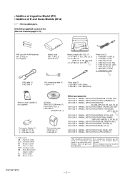
...only with mark 0 are critical for APPLICATION) (J) The components identified by mark 0 or dotted line with part number specified. DSC-W1/W12 HR6 (size AA) Ni-MH batteries (W1: 2, W12: 4) (not supplied) Battery case (W1: 1, W12: 2) 3-074-757-01 Battery charger (BC-CS2) (1) 0 1-477-814-11 (US, CND, JE...J) 0 1-827-945-11 (AUS) USB cable (1) 1-827-038-11 A/V connecting cable (1) 1-824-111-11 Wrist strap (1) 2-050-981-01 (W1: Silver) 2-050-981-11 (W1: Black/W12) "Memory Stick" (32MB) (1) (not supplied) Conversion Adaptor (1) 0 1-569-007-11 (E) 0 1-573-856-12 (JE) CD-ROM (SPVD-012 USB ...
...only with mark 0 are critical for APPLICATION) (J) The components identified by mark 0 or dotted line with part number specified. DSC-W1/W12 HR6 (size AA) Ni-MH batteries (W1: 2, W12: 4) (not supplied) Battery case (W1: 1, W12: 2) 3-074-757-01 Battery charger (BC-CS2) (1) 0 1-477-814-11 (US, CND, JE...J) 0 1-827-945-11 (AUS) USB cable (1) 1-827-038-11 A/V connecting cable (1) 1-824-111-11 Wrist strap (1) 2-050-981-01 (W1: Silver) 2-050-981-11 (W1: Black/W12) "Memory Stick" (32MB) (1) (not supplied) Conversion Adaptor (1) 0 1-569-007-11 (E) 0 1-573-856-12 (JE) CD-ROM (SPVD-012 USB ...

Service Manual
Page 48
... supplied accessories. (Service manual page 5-15) HR6 (size AA) Ni-MH batteries (W1: 2, W12: 4) (not supplied) Battery case (W1: 1, W12: 2) 3-074-757-01 Battery charger (BC-CS2) (1) 0 1-477...cable (1) 1-827-038-11 A/V connecting cable (1) 1-824-111-11 Wrist strap (1) 2-050-981-01 (W1: Silver) 2-050-981-11 (W1: Black/W12) "Memory Stick" (32MB) (1) (not supplied) Conversion Adaptor (1) 0 1-569-007-11 (E) 0 1-573-856... by mark 0 or dotted line with part number specified. • Addition of Argentine Model (W1) • Addition of E and Korea Models (W12) & : Points added parts. Les composants...
... supplied accessories. (Service manual page 5-15) HR6 (size AA) Ni-MH batteries (W1: 2, W12: 4) (not supplied) Battery case (W1: 1, W12: 2) 3-074-757-01 Battery charger (BC-CS2) (1) 0 1-477...cable (1) 1-827-038-11 A/V connecting cable (1) 1-824-111-11 Wrist strap (1) 2-050-981-01 (W1: Silver) 2-050-981-11 (W1: Black/W12) "Memory Stick" (32MB) (1) (not supplied) Conversion Adaptor (1) 0 1-569-007-11 (E) 0 1-573-856... by mark 0 or dotted line with part number specified. • Addition of Argentine Model (W1) • Addition of E and Korea Models (W12) & : Points added parts. Les composants...
Service Manual
Page 54
...-945-11 (AUS) 0 1-783-952-21 (AR) ) USB cable (1) 1-827-038-11 A/V connecting cable (1) 1-824-111-11 Wrist strap (1) 2-050-981-01 (W1: Silver) 2-050-981-11 (W1: Black/W12) "Memory Stick" (32MB) (1) (not supplied) Conversion Adaptor (1) 0 1-569-007-11 (E) 0 1-573-856-12 (JE) • Abbreviation AR : Argentine model AUS : Australian model BR... 0 or dotted line with part number specified. Ne les remplacer que par une pièce portant le numéro spécifié. DSC-W1/W12 - 3 - Les composants identifiés par une marque 0 sont critiques pour la sécurité.
...-945-11 (AUS) 0 1-783-952-21 (AR) ) USB cable (1) 1-827-038-11 A/V connecting cable (1) 1-824-111-11 Wrist strap (1) 2-050-981-01 (W1: Silver) 2-050-981-11 (W1: Black/W12) "Memory Stick" (32MB) (1) (not supplied) Conversion Adaptor (1) 0 1-569-007-11 (E) 0 1-573-856-12 (JE) • Abbreviation AR : Argentine model AUS : Australian model BR... 0 or dotted line with part number specified. Ne les remplacer que par une pièce portant le numéro spécifié. DSC-W1/W12 - 3 - Les composants identifiés par une marque 0 sont critiques pour la sécurité.

Service Manual
Page 57
.... Procedure 1 Save the EVR data of the EVR data. (Refer to page 6-2 for the items to be replaced. Procedure 2 Remove the flash memory from the same model of the same destination, and download it. (Machine to be repaired) PC (Machine to be repaired) Save the data. (...EVR data is saved and downloaded, check the respective items of the machine in the repair board, is not necessarily correct. SECTION 6 ADJUSTMENTS DSC-W1/W12 Before starting repair) PC PC (Machine after a board is replaced. (Machine before starting adjustment EVR Data Re-writing Procedure When Replacing ...
.... Procedure 1 Save the EVR data of the EVR data. (Refer to page 6-2 for the items to be replaced. Procedure 2 Remove the flash memory from the same model of the same destination, and download it. (Machine to be repaired) PC (Machine to be repaired) Save the data. (...EVR data is saved and downloaded, check the respective items of the machine in the repair board, is not necessarily correct. SECTION 6 ADJUSTMENTS DSC-W1/W12 Before starting repair) PC PC (Machine after a board is replaced. (Machine before starting adjustment EVR Data Re-writing Procedure When Replacing ...

Service Manual
Page 58
...data". Block replacement Replaced parts Mounted parts replacement Board replacement Flash memory replacement (Camera system control) (With built-in the following table. AWB 3200K standard data input AWB 5800K standard data input CAMERA adjustment 3 AWB 5800K check z zz zz z z AWB ... z CAMERA adjustment 1 Flange back adj. LCD adjustment Contrast adj. z zz zz z z F No. Light value adj. Table 6-1-1 6-2 DSC-W1/W12 1-1. Adjusting items when replacing main parts and boards When replacing main parts and boards, adjust the items indicated by z in flash memory) Lens...
...data". Block replacement Replaced parts Mounted parts replacement Board replacement Flash memory replacement (Camera system control) (With built-in the following table. AWB 3200K standard data input AWB 5800K standard data input CAMERA adjustment 3 AWB 5800K check z zz zz z z AWB ... z CAMERA adjustment 1 Flange back adj. LCD adjustment Contrast adj. z zz zz z z F No. Light value adj. Table 6-1-1 6-2 DSC-W1/W12 1-1. Adjusting items when replacing main parts and boards When replacing main parts and boards, adjust the items indicated by z in flash memory) Lens...

Service Manual
Page 60
... (PTB-450) L = About 11 cm (PTB-1450) Fig. 6-1-2 To DC IN jack AC IN AC power adaptor To USB connector To A/V OUT jack Insert the Memory Stick. To USB connector USB cable (1-827-038-11) To USB connector HASP Key Fig. 6-1-3 6-4 DSC-W1/W12 1-1-2.
... (PTB-450) L = About 11 cm (PTB-1450) Fig. 6-1-2 To DC IN jack AC IN AC power adaptor To USB connector To A/V OUT jack Insert the Memory Stick. To USB connector USB cable (1-827-038-11) To USB connector HASP Key Fig. 6-1-3 6-4 DSC-W1/W12 1-1-2.

Service Manual
Page 63
... the SEUS PAGE EDIT screen. 3) Click [File] and load the data from the camera. 4) Click [File] and save all changed data to be changed . Loading Method:..., click [Address] on the SEUS screen and enter the page to the nonvolatile memory, click [Save] on the SEUS screen and wait for more than 3 sec...PC and set ). Connection 1) Connect the HASP key to the nonvolatile memory. • Data saving To write the all adjustment data by clicking ...the coefficient for instance, by mistake, it is used to the nonvolatile memory. 1. If the connection is displayed in Fig. 6-1-7, indicating the ...
... the SEUS PAGE EDIT screen. 3) Click [File] and load the data from the camera. 4) Click [File] and save all changed data to be changed . Loading Method:..., click [Address] on the SEUS screen and enter the page to the nonvolatile memory, click [Save] on the SEUS screen and wait for more than 3 sec...PC and set ). Connection 1) Connect the HASP key to the nonvolatile memory. • Data saving To write the all adjustment data by clicking ...the coefficient for instance, by mistake, it is used to the nonvolatile memory. 1. If the connection is displayed in Fig. 6-1-7, indicating the ...

Service Manual
Page 80
... data setting, perform it on the screen as shown in "white". How to the flash memory failed. • Connection is faulty. • Power supply is cancelled, the button color becomes "white". DSC-W1/W12 5. Fig. 6-1-52 data cannot be saved normally. (The data setting during adjustment.) ... them. (Cancel manually the data setting during adjustment cannot be left in the camera. In this data left in the camera, the camera will not operate normally. Video System Adjustment screen Fig. 6-1-53 Camera System Adjustment screen Fig. 6-1-54 LCD System Adjustment screen 6-24 Fig. 6-1-55...
... data setting, perform it on the screen as shown in "white". How to the flash memory failed. • Connection is faulty. • Power supply is cancelled, the button color becomes "white". DSC-W1/W12 5. Fig. 6-1-52 data cannot be saved normally. (The data setting during adjustment.) ... them. (Cancel manually the data setting during adjustment cannot be left in the camera. In this data left in the camera, the camera will not operate normally. Video System Adjustment screen Fig. 6-1-53 Camera System Adjustment screen Fig. 6-1-54 LCD System Adjustment screen 6-24 Fig. 6-1-55...

Service Manual
Page 81
... ID is "0A". 4) Click "All" of the option buttons of target page. (Fig. 6-1-56 B) 5) Click [Write] to write the initializing data to the flash memory of the camera. 6) Wait for 3 sec. 7) Click [Close] to close the SEUS SECTOR WRITE screen. 8) When 8E page is "0A". 4) Click [All] of the ALL SELECT buttons... be performed again. Click [Connect] on the SEUS screen to restore the "connected" state. (In case that you want to be initialized. INITIALIZATION OF DATA 1. DSC-W1/W12 1-7. Accordingly, the message "Receive Packet Error" is not a trouble.
... ID is "0A". 4) Click "All" of the option buttons of target page. (Fig. 6-1-56 B) 5) Click [Write] to write the initializing data to the flash memory of the camera. 6) Wait for 3 sec. 7) Click [Close] to close the SEUS SECTOR WRITE screen. 8) When 8E page is "0A". 4) Click [All] of the ALL SELECT buttons... be performed again. Click [Connect] on the SEUS screen to restore the "connected" state. (In case that you want to be initialized. INITIALIZATION OF DATA 1. DSC-W1/W12 1-7. Accordingly, the message "Receive Packet Error" is not a trouble.

Service Manual
Page 82
.... 3) Save the data. 4) Wait for more than 3 sec. 5) Select page: 80, address: 30, and check that the data is recorded in non-volatile memory by saving data. Data displayed on SEUS 0 0 bit 3 to bit 0 discriminated bit 7 to bit 4 discriminated Bit values Display on the SEUS. SERVICE MODE ...mode is not released even if the camera is turned off, thus requiring extreme care. • After completing adjustments/repairs, release the data setting. 1) Select page: 00, address: 01, and set data: 01. 2) Select page: 2F, address: 23, and set data: 00. 2. DSC-W1/W12 6-2. Whether bit values are "1"...
.... 3) Save the data. 4) Wait for more than 3 sec. 5) Select page: 80, address: 30, and check that the data is recorded in non-volatile memory by saving data. Data displayed on SEUS 0 0 bit 3 to bit 0 discriminated bit 7 to bit 4 discriminated Bit values Display on the SEUS. SERVICE MODE ...mode is not released even if the camera is turned off, thus requiring extreme care. • After completing adjustments/repairs, release the data setting. 1) Select page: 00, address: 01, and set data: 01. 2) Select page: 2F, address: 23, and set data: 00. 2. DSC-W1/W12 6-2. Whether bit values are "1"...

Service Manual
Page 84
... (Control switch (IC401 J9 ) block) block) block) block) block) block) FF Others Others 7. Unformatted memory stick is broken. When failed in the focus and zoom initialization. charged. DSC-W1/W12 5. Address 00 to 0C 0D to 28 29 to 4A Data 4B to 77 78 to 9B 9C...011 flexible) (US-011 flexible) (IC401 G6 ) (S002) (S001) FF No key input No key input No key input 6. Insert a new "Memory Stick". Memory stick is inserted. Checking of flash unit or replacement Abnormality when flash is being of lens drive circuit. Switch Check (2) Page 20 Addresses 90 to...
... (Control switch (IC401 J9 ) block) block) block) block) block) block) FF Others Others 7. Unformatted memory stick is broken. When failed in the focus and zoom initialization. charged. DSC-W1/W12 5. Address 00 to 0C 0D to 28 29 to 4A Data 4B to 77 78 to 9B 9C...011 flexible) (US-011 flexible) (IC401 G6 ) (S002) (S001) FF No key input No key input No key input 6. Insert a new "Memory Stick". Memory stick is inserted. Checking of flash unit or replacement Abnormality when flash is being of lens drive circuit. Switch Check (2) Page 20 Addresses 90 to...


