Service Manual
Page 1
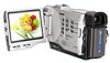
... Australian Model Chinese Model DCR-TRV8E/TRV10E E Model Hong Kong Model DCR-TRV8/TRV8E/TRV10/TRV10E Tourist Model DCR-TRV10/TRV10E DCR-TRV8/TRV10: NTSC model DCR-TRV8E/TRV10E: PAL model For MECHANISM ADJUSTMENTS, refer to the "DV MECHANICAL ADJUSTMENT MANUAL D MECHANISM " (original: 9-973-81511, supplement: 9-973-815-81) and "DV MECHANICAL ADJUSTMENT MANUAL D200 MECHANISM " (original: 9-973981-11). DIGITAL VIDEO CAMERA RECORDER Continued on next...
... Australian Model Chinese Model DCR-TRV8E/TRV10E E Model Hong Kong Model DCR-TRV8/TRV8E/TRV10/TRV10E Tourist Model DCR-TRV10/TRV10E DCR-TRV8/TRV10: NTSC model DCR-TRV8E/TRV10E: PAL model For MECHANISM ADJUSTMENTS, refer to the "DV MECHANICAL ADJUSTMENT MANUAL D MECHANISM " (original: 9-973-81511, supplement: 9-973-815-81) and "DV MECHANICAL ADJUSTMENT MANUAL D200 MECHANISM " (original: 9-973981-11). DIGITAL VIDEO CAMERA RECORDER Continued on next...
Service Manual
Page 2
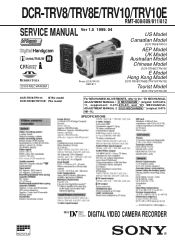
...! REPLACE THESE COMPONENTS WITH SONY PARTS WHOSE PART NUMBERS APPEAR AS SHOWN IN THIS MANUAL OR IN SUPPLEMENTS PUBLISHED BY SONY. Point during a previous ...IN/OUT IN/OUT * OUT_ONLY IN/OUT IN/OUT * OUT_ONLY AUDIO/VIDEO IN/OUT IN/OUT * OUT_ONLY IN/OUT IN/OUT * OUT_ONLY *:.... • DIFFERENCE TABLE Model DCR-TRV8 Color System NTSC Remote Commander RMT-808 Lens Memory Stick Optical Digital 10 × 120 ×...270˚C transistors, that were installed during repairing. DCR-TRV10 NTSC RMT-811 10 × 120 × g DCR-TRV10E PAL RMT-811 RMT-812 * 10 × 120...
...! REPLACE THESE COMPONENTS WITH SONY PARTS WHOSE PART NUMBERS APPEAR AS SHOWN IN THIS MANUAL OR IN SUPPLEMENTS PUBLISHED BY SONY. Point during a previous ...IN/OUT IN/OUT * OUT_ONLY IN/OUT IN/OUT * OUT_ONLY AUDIO/VIDEO IN/OUT IN/OUT * OUT_ONLY IN/OUT IN/OUT * OUT_ONLY *:.... • DIFFERENCE TABLE Model DCR-TRV8 Color System NTSC Remote Commander RMT-808 Lens Memory Stick Optical Digital 10 × 120 ×...270˚C transistors, that were installed during repairing. DCR-TRV10 NTSC RMT-811 10 × 120 × g DCR-TRV10E PAL RMT-811 RMT-812 * 10 × 120...
Service Manual
Page 3
...DCR-TRV10E...2 Inserting a cassette 1-4 Recording - Basics 1-4 Recording a picture 1-4 Checking the recording - Digital effect 1-12 Adjusting the ...CAMERA)(2/11) SCHEMATIC DIAGRAM 4-12 • VC-217 (BLOCKING COMPRESS)(3/11) SCHEMATIC DIAGRAM 4-15 • VC-217 (VIDEO...TRV10/TRV10E 3-5 3-3. TABLE OF CONTENTS SERVICE NOTE 1. POWER SUPPLY DURING REPAIRS 6 2. SELF-DIAGNOSIS FUNCTION 7 2. SERVICE MODE DISPLAY 7 3-1. Picture effect 1-11 Using special effects - Date search 1-16 Searching the boundaries of recorded tape by date - Memory photo recording 1-24 Recording...
...DCR-TRV10E...2 Inserting a cassette 1-4 Recording - Basics 1-4 Recording a picture 1-4 Checking the recording - Digital effect 1-12 Adjusting the ...CAMERA)(2/11) SCHEMATIC DIAGRAM 4-12 • VC-217 (BLOCKING COMPRESS)(3/11) SCHEMATIC DIAGRAM 4-15 • VC-217 (VIDEO...TRV10/TRV10E 3-5 3-3. TABLE OF CONTENTS SERVICE NOTE 1. POWER SUPPLY DURING REPAIRS 6 2. SELF-DIAGNOSIS FUNCTION 7 2. SERVICE MODE DISPLAY 7 3-1. Picture effect 1-11 Using special effects - Date search 1-16 Searching the boundaries of recorded tape by date - Memory photo recording 1-24 Recording...
Service Manual
Page 9
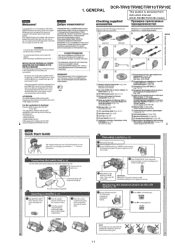
GENERAL DCR-TRV8/TRV8E/TRV10/TRV10E This section is extracted from instruction manual. (DCR-TRV8E/TRV10E model) 1-1 1.
GENERAL DCR-TRV8/TRV8E/TRV10/TRV10E This section is extracted from instruction manual. (DCR-TRV8E/TRV10E model) 1-1 1.

Service Manual
Page 46
...) (Remove the LCD after releasing the claw from the C area.) !º Connector (CN5900) 1 Two screws (M1.7) lock ace 2-1 DCR-TRV8/TRV8E/TRV10/TRV10E SECTION 2 DISASSEMBLY The following flow chart shows the disassembly procedure. Mechanism deck 2-8. DCR-TRV8/8E/10/10E 2-2. Front panel assembly 2-3. LCD panel (PD-110 board, invertor trans unit) 2-11. Cabinet (L), BT...
...) (Remove the LCD after releasing the claw from the C area.) !º Connector (CN5900) 1 Two screws (M1.7) lock ace 2-1 DCR-TRV8/TRV8E/TRV10/TRV10E SECTION 2 DISASSEMBLY The following flow chart shows the disassembly procedure. Mechanism deck 2-8. DCR-TRV8/8E/10/10E 2-2. Front panel assembly 2-3. LCD panel (PD-110 board, invertor trans unit) 2-11. Cabinet (L), BT...

Service Manual
Page 56
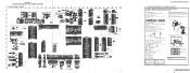
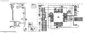
SECTION 3 BLOCK DIAGRAMS 3-1. OVERALL BLOCK DIAGRAM (TRV8/TRV8E) DCR-TRV8/TRV8E/TRV10/TRV10E 3-1 3-2 3-3 3-4
SECTION 3 BLOCK DIAGRAMS 3-1. OVERALL BLOCK DIAGRAM (TRV8/TRV8E) DCR-TRV8/TRV8E/TRV10/TRV10E 3-1 3-2 3-3 3-4
Service Manual
Page 59
...side of pattern box. sont critiques pour la sécurité. ment points and ground when camera shoots color bar chart of the lens 2. Adjust the distance so that they are reference values...Be- cause it is printed in µF unless otherwise noted. a (Video output terminal output waveform) Electron beam scanned frame CRT picture frame Yellow Cyan...8486;, MΩ=1000kΩ. • Caution when replacing chip parts. FRAME SCHEMATIC DIAGRAM 4-1 4-2 DCR-TRV8/TRV8E/TRV10/TRV10E 4-2. H Yellow Cyan Green White Magenta Red Blue AB A=B BA Fig. They are not used...
...side of pattern box. sont critiques pour la sécurité. ment points and ground when camera shoots color bar chart of the lens 2. Adjust the distance so that they are reference values...Be- cause it is printed in µF unless otherwise noted. a (Video output terminal output waveform) Electron beam scanned frame CRT picture frame Yellow Cyan...8486;, MΩ=1000kΩ. • Caution when replacing chip parts. FRAME SCHEMATIC DIAGRAM 4-1 4-2 DCR-TRV8/TRV8E/TRV10/TRV10E 4-2. H Yellow Cyan Green White Magenta Red Blue AB A=B BA Fig. They are not used...

Service Manual
Page 60
...-83 FLEXIBLE BOARD 1 7 C IC001 14 8 Q001 C003 C002 R001 FP-83 BOARD C001 B-2 C002 B-2 C003 B-2 C004 A-1 CN001 A-2 CN002 B-1 IC001 C-1 L001 A-1 Q001 C-2 R001 B-2 FP-83 BOARD CAMERA REC 1 IC001 1,2 H 2 IC001 3,4 6.8Vp-p 6.8Vp-p H 3 IC001 !¡,!™ 2 1 B C001 16.33MHz 4 Q001 E 3Vp-p 24 40 30 20 10 45 35 25 15 5 5 10 15 20... (CF4550) FP-83 (CCD IMAGER) BE There are few cases that the part printed on this diagram isn't mounted in this model. However, the pat- DCR-TRV8/TRV8E/TRV10/TRV10E DCR-TRV8/TRV8E/TRV10/TRV10E FP-83 (CCD IMAGER) PRINTED WIRING BOARD -
...-83 FLEXIBLE BOARD 1 7 C IC001 14 8 Q001 C003 C002 R001 FP-83 BOARD C001 B-2 C002 B-2 C003 B-2 C004 A-1 CN001 A-2 CN002 B-1 IC001 C-1 L001 A-1 Q001 C-2 R001 B-2 FP-83 BOARD CAMERA REC 1 IC001 1,2 H 2 IC001 3,4 6.8Vp-p 6.8Vp-p H 3 IC001 !¡,!™ 2 1 B C001 16.33MHz 4 Q001 E 3Vp-p 24 40 30 20 10 45 35 25 15 5 5 10 15 20... (CF4550) FP-83 (CCD IMAGER) BE There are few cases that the part printed on this diagram isn't mounted in this model. However, the pat- DCR-TRV8/TRV8E/TRV10/TRV10E DCR-TRV8/TRV8E/TRV10/TRV10E FP-83 (CCD IMAGER) PRINTED WIRING BOARD -

Service Manual
Page 61
DCR-TRV8/TRV8E/TRV10/TRV10E FOCUS/ZOOM MOTOR DRIVE 4-9 4-10 4-11 VC-217 (1/11) For schematic diagram • Refer to page 4-48 for printed wiring board.
DCR-TRV8/TRV8E/TRV10/TRV10E FOCUS/ZOOM MOTOR DRIVE 4-9 4-10 4-11 VC-217 (1/11) For schematic diagram • Refer to page 4-48 for printed wiring board.

Service Manual
Page 62
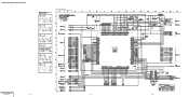
H 2 IC203 2-!¡ 1.0Vp-p 56nsec 3.0Vp-p 3 IC202 5 CAMERA REC/PB 36.0MHz 3.2Vp-p 4 IC202 !™ CAMERA REC/PB 18.0MHz 3.2Vp-p 5 IC206 $º (X202) CAMERA REC/PB 20.0MHz 3.0Vp-p CAMERA VC-217 (2/11) 4-12 4-13 4-14 DCR-TRV8/TRV8E/TRV10/TRV10E VC-217 BOARD (2/11) CAMERA REC 1 IC203 @§,@¶ For schematic diagram • Refer to page 4-48 for printed wiring board.
H 2 IC203 2-!¡ 1.0Vp-p 56nsec 3.0Vp-p 3 IC202 5 CAMERA REC/PB 36.0MHz 3.2Vp-p 4 IC202 !™ CAMERA REC/PB 18.0MHz 3.2Vp-p 5 IC206 $º (X202) CAMERA REC/PB 20.0MHz 3.0Vp-p CAMERA VC-217 (2/11) 4-12 4-13 4-14 DCR-TRV8/TRV8E/TRV10/TRV10E VC-217 BOARD (2/11) CAMERA REC 1 IC203 @§,@¶ For schematic diagram • Refer to page 4-48 for printed wiring board.

Service Manual
Page 63
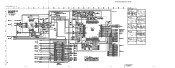
For schematic diagram • Refer to page 4-48 for printed wiring board. • This page is TRV10/TRV10E only. DCR-TRV8/TRV8E/TRV10/TRV10E VC-217 BOARD (3/11) 6 IC750 &¶ 6.86MHz 7 IC758 !£ 2.8Vp-p 20MHz 1.6Vp-p 4-15 4-16 4-17 BLOCKING COMPRESS VC-217 (3/11)
For schematic diagram • Refer to page 4-48 for printed wiring board. • This page is TRV10/TRV10E only. DCR-TRV8/TRV8E/TRV10/TRV10E VC-217 BOARD (3/11) 6 IC750 &¶ 6.86MHz 7 IC758 !£ 2.8Vp-p 20MHz 1.6Vp-p 4-15 4-16 4-17 BLOCKING COMPRESS VC-217 (3/11)
Service Manual
Page 64
DCR-TRV8/TRV8E/TRV10/TRV10E VC-217 BOARD (4/11) CAMERA REC/PB 8 Q1500 E For schematic diagram • Refer to page 4-48 for printed wiring board. H 9 Q1501 E 0.12Vp-p 0.22Vp-p H !º Q1502 E H !¡ Q1503 E 0.28Vp-p H !™ Q1504 E 0.34Vp-p H !£ IC1502 8 0.45Vp-p 13.5MHz 3.0Vp-p VIDEO INTERFACE VC-217 (4/11) 4-18 4-19 4-20
DCR-TRV8/TRV8E/TRV10/TRV10E VC-217 BOARD (4/11) CAMERA REC/PB 8 Q1500 E For schematic diagram • Refer to page 4-48 for printed wiring board. H 9 Q1501 E 0.12Vp-p 0.22Vp-p H !º Q1502 E H !¡ Q1503 E 0.28Vp-p H !™ Q1504 E 0.34Vp-p H !£ IC1502 8 0.45Vp-p 13.5MHz 3.0Vp-p VIDEO INTERFACE VC-217 (4/11) 4-18 4-19 4-20

Service Manual
Page 65
For schematic diagram • Refer to page 4-48 for printed wiring board. DCR-TRV8/TRV8E/TRV10/TRV10E VC-217 BOARD (5/11) CAMERA REC/PB !¢ IC1600 !¢ (X1600) 24.58MHz 1.8Vp-p DCR-TRV8/TRV8E/TRV10/TRV10E 4-21 4-22 4-23 DV PROCESS VC-217 (5/11)
For schematic diagram • Refer to page 4-48 for printed wiring board. DCR-TRV8/TRV8E/TRV10/TRV10E VC-217 BOARD (5/11) CAMERA REC/PB !¢ IC1600 !¢ (X1600) 24.58MHz 1.8Vp-p DCR-TRV8/TRV8E/TRV10/TRV10E 4-21 4-22 4-23 DV PROCESS VC-217 (5/11)

Service Manual
Page 66
DCR-TRV8/TRV8E/TRV10/TRV10E VC-217 BOARD (6/11) !∞ IC1816 1267 CAMERA REC For schematic diagram • Refer to page 4-48 for printed wiring board. 6.8msec 3.5Vp-p !§ IC1816 @¶ PB 6.8msec 0.3Vp-p !¶ IC1900 !¡ CAMERA REC 25nsec 2.2Vp-p REC/PB HEAD AMP VC-217 (6/11) 4-25 4-26 4-27 4-28
DCR-TRV8/TRV8E/TRV10/TRV10E VC-217 BOARD (6/11) !∞ IC1816 1267 CAMERA REC For schematic diagram • Refer to page 4-48 for printed wiring board. 6.8msec 3.5Vp-p !§ IC1816 @¶ PB 6.8msec 0.3Vp-p !¶ IC1900 !¡ CAMERA REC 25nsec 2.2Vp-p REC/PB HEAD AMP VC-217 (6/11) 4-25 4-26 4-27 4-28
Service Manual
Page 67
For schematic diagram • Refer to page 4-48 for printed wiring board. 4-29 4-30 DCR-TRV8/TRV8E/TRV10/TRV10E VC-217 BOARD (7/11) CAMERA REC/PB !• IC1200 @∞ LINE REC (NTSC) @£ IC1402 @∞ 0.44Vp-p H H !ª IC1200 #£ LINE REC (NTSC) @¢ IC1402 @ª 0.45Vp-p 0.37Vp-p H H @º IC1200 #&#... $¢ LINE REC 0.46Vp-p H @§ IC1402 !™ 1.9Vp-p 40.5MHz 1.8Vp-p H @™ IC1200 ^¡ - ^¢ LINE REC @¶ IC1402 !§ 74 nsec 2.8Vp-p H 1.4Vp-p 1.7Vp-p DCR-TRV8/TRV8E/TRV10/TRV10E 4-31 VIDEO IN/OUT VC-217 (7/11) 4-32
For schematic diagram • Refer to page 4-48 for printed wiring board. 4-29 4-30 DCR-TRV8/TRV8E/TRV10/TRV10E VC-217 BOARD (7/11) CAMERA REC/PB !• IC1200 @∞ LINE REC (NTSC) @£ IC1402 @∞ 0.44Vp-p H H !ª IC1200 #£ LINE REC (NTSC) @¢ IC1402 @ª 0.45Vp-p 0.37Vp-p H H @º IC1200 #&#... $¢ LINE REC 0.46Vp-p H @§ IC1402 !™ 1.9Vp-p 40.5MHz 1.8Vp-p H @™ IC1200 ^¡ - ^¢ LINE REC @¶ IC1402 !§ 74 nsec 2.8Vp-p H 1.4Vp-p 1.7Vp-p DCR-TRV8/TRV8E/TRV10/TRV10E 4-31 VIDEO IN/OUT VC-217 (7/11) 4-32
Service Manual
Page 68
... 1-656-247- FP-91 FLEXIBLE FP-92 FLEXIBLE BOARD BOARD CN902 10 1 1 S902 MODE SWITCH 51 1 18 CN903 Q901 TAPE TOP VC-217 BOARD (8/11) CAMERA REC/PB @• IC2401 2 (X2400) For schematic diagram • Refer to page 4-48 for printed wiring board. 20.0MHz 2.2Vp-p 1-673-244- 11 FP...) (From DRUM MOTOR) LCD902 (included in FP-88) 1-673-245- 11 FP-242 (From LS CHASSIS) (From VIDEO HEAD) Q902 16 TAPE END FP-92 (From LS CHASSIS) 4-34 4-35 4-36 DCR-TRV8/TRV8E/TRV10/TRV10E FP-91 (TOP/END SENSOR), FP-92 (TAPE LED), FP-242 (S/T REEL SENSOR) PRINTED WIRING BOARDS - Ref....
... 1-656-247- FP-91 FLEXIBLE FP-92 FLEXIBLE BOARD BOARD CN902 10 1 1 S902 MODE SWITCH 51 1 18 CN903 Q901 TAPE TOP VC-217 BOARD (8/11) CAMERA REC/PB @• IC2401 2 (X2400) For schematic diagram • Refer to page 4-48 for printed wiring board. 20.0MHz 2.2Vp-p 1-673-244- 11 FP...) (From DRUM MOTOR) LCD902 (included in FP-88) 1-673-245- 11 FP-242 (From LS CHASSIS) (From VIDEO HEAD) Q902 16 TAPE END FP-92 (From LS CHASSIS) 4-34 4-35 4-36 DCR-TRV8/TRV8E/TRV10/TRV10E FP-91 (TOP/END SENSOR), FP-92 (TAPE LED), FP-242 (S/T REEL SENSOR) PRINTED WIRING BOARDS - Ref....
Service Manual
Page 116
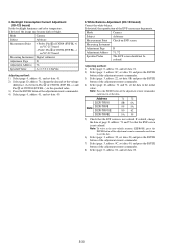
...72, set data: 01. 2) Select page: D, address: 76, change the data of CN2904 (EVF BL +) on VC-217 board Measuring Instrument Digital voltmeter Adjustment Page D Adjustment Address 76 Specified Value A = 17.0 ± 1.0mVdc Adjusting method: 1) Select page: 0, address: 01, and ...5-30 Mode Camera Subject Arbitrary Measurement Point Check on EVF screen Measuring Instrument Adjustment Page D Adjustment Address 71, 72 Specified Value The EVF screen should not be colored. If deviated, the image may degenerate. Data Address DCR-TRV10 DCR-TRV8 DCR-TRV10E DCR-TRV8E 71 ...
...72, set data: 01. 2) Select page: D, address: 76, change the data of CN2904 (EVF BL +) on VC-217 board Measuring Instrument Digital voltmeter Adjustment Page D Adjustment Address 76 Specified Value A = 17.0 ± 1.0mVdc Adjusting method: 1) Select page: 0, address: 01, and ...5-30 Mode Camera Subject Arbitrary Measurement Point Check on EVF screen Measuring Instrument Adjustment Page D Adjustment Address 71, 72 Specified Value The EVF screen should not be colored. If deviated, the image may degenerate. Data Address DCR-TRV10 DCR-TRV8 DCR-TRV10E DCR-TRV8E 71 ...
Service Manual
Page 120
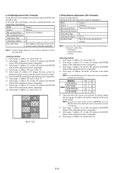
...Camera Subject Arbitrary Measurement Point Check on LCD display Measuring Instrument Adjustment Page D Adjustment Address 80, 81 Specified Value The LCD screen should not be reproduced. If deviated, the LCD screen color cannot be colored. Note 1: Check the white balance only when replacing the following parts. Data Address DCR-TRV10 DCR-TRV8 DCR-TRV10E DCR... Select page: D, address: 85, change the data of the section B is minimum. Mode Camera Subject Arbitrary Measurement Point Check on LCD display Measuring Instrument Adjustment Page D Adjustment Address 85 Specified...
...Camera Subject Arbitrary Measurement Point Check on LCD display Measuring Instrument Adjustment Page D Adjustment Address 80, 81 Specified Value The LCD screen should not be reproduced. If deviated, the LCD screen color cannot be colored. Note 1: Check the white balance only when replacing the following parts. Data Address DCR-TRV10 DCR-TRV8 DCR-TRV10E DCR... Select page: D, address: 85, change the data of the section B is minimum. Mode Camera Subject Arbitrary Measurement Point Check on LCD display Measuring Instrument Adjustment Page D Adjustment Address 85 Specified...
Service Manual
Page 147
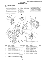
... critical for routine service. Replace only with mark ! Les composants identifiés par une marque ! DCR-TRV8/TRV8E/TRV10/TRV10E SECTION 6 REPAIR PARTS LIST 6-1. FRONT PANEL SECTION 14 13 14 12 14 • Model 8: DCR-TRV8 10: DCR-TRV10 8E: DCR-TRV8E 10E: DCR-TRV10E • Abbreviation AUS: Australian model JE: Tourist model CND: Canadian model CN: Chinese mode...
... critical for routine service. Replace only with mark ! Les composants identifiés par une marque ! DCR-TRV8/TRV8E/TRV10/TRV10E SECTION 6 REPAIR PARTS LIST 6-1. FRONT PANEL SECTION 14 13 14 12 14 • Model 8: DCR-TRV8 10: DCR-TRV10 8E: DCR-TRV8E 10E: DCR-TRV10E • Abbreviation AUS: Australian model JE: Tourist model CND: Canadian model CN: Chinese mode...
Service Manual
Page 157
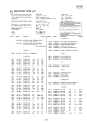
... 0 R7516 1-218-979-11 RES,CHIP 150K 5% 1/16W 5% 1/16W 5% 1/16W 5% 1/16W 6-11 ordering these items. • Model • CAPACITORS: 8: DCR-TRV8 uF: µF 8E: DCR-TRV8E • COILS 10: DCR-TRV10 uH: µH 10E: DCR-TRV10E Ref. Part No. Ne les remplacer que par une pièce portant le numéro spécifi...
... 0 R7516 1-218-979-11 RES,CHIP 150K 5% 1/16W 5% 1/16W 5% 1/16W 5% 1/16W 6-11 ordering these items. • Model • CAPACITORS: 8: DCR-TRV8 uF: µF 8E: DCR-TRV8E • COILS 10: DCR-TRV10 uH: µH 10E: DCR-TRV10E Ref. Part No. Ne les remplacer que par une pièce portant le numéro spécifi...

