Service Manual
Page 1
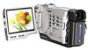
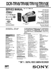
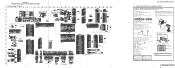
Continued on next page - DIGITAL VIDEO CAMERA RECORDER SPECIFICATIONS MICROFILM - DCR-TRV8/TRV8E/TRV10/TRV10E RMT-808/809/811/812 SERVICE MANUAL Ver 1.0 1999. 04 D300 MECHANISM Photo: DCR-TRV10 RMT-811 US Model Canadian Model DCR-TRV8/TRV10 AEP Model UK Model Australian Model Chinese Model DCR-TRV8E/TRV10E E Model Hong Kong Model DCR-TRV8/TRV8E/TRV10/TRV10E Tourist Model DCR-TRV10/TRV10E DCR-TRV8/TRV10: NTSC model DCR-TRV8E/TRV10E: PAL model For MECHANISM ADJUSTMENTS, refer to the "DV MECHANICAL ADJUSTMENT MANUAL D MECHANISM " (original: 9-973-81511...
Continued on next page - DIGITAL VIDEO CAMERA RECORDER SPECIFICATIONS MICROFILM - DCR-TRV8/TRV8E/TRV10/TRV10E RMT-808/809/811/812 SERVICE MANUAL Ver 1.0 1999. 04 D300 MECHANISM Photo: DCR-TRV10 RMT-811 US Model Canadian Model DCR-TRV8/TRV10 AEP Model UK Model Australian Model Chinese Model DCR-TRV8E/TRV10E E Model Hong Kong Model DCR-TRV8/TRV8E/TRV10/TRV10E Tourist Model DCR-TRV10/TRV10E DCR-TRV8/TRV10: NTSC model DCR-TRV8E/TRV10E: PAL model For MECHANISM ADJUSTMENTS, refer to the "DV MECHANICAL ADJUSTMENT MANUAL D MECHANISM " (original: 9-973-81511...
Service Manual
Page 2
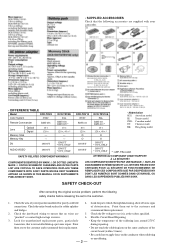
... the customer. 1. Look for parts which, through functioning, show obvious signs connections. them out to the customer and recommend their replacement. 2. Check the interboard wiring to apply force on the same conductor of your camcorder. • DIFFERENCE TABLE Model DCR-TRV8 Color System NTSC Remote Commander RMT-808 Lens Memory Stick Optical Digital 10 × 120 × - Point during a previous repair. COMPONENTS IDENTIFIED BY MARK ! LES...
... the customer. 1. Look for parts which, through functioning, show obvious signs connections. them out to the customer and recommend their replacement. 2. Check the interboard wiring to apply force on the same conductor of your camcorder. • DIFFERENCE TABLE Model DCR-TRV8 Color System NTSC Remote Commander RMT-808 Lens Memory Stick Optical Digital 10 × 120 × - Point during a previous repair. COMPONENTS IDENTIFIED BY MARK ! LES...
Service Manual
Page 3
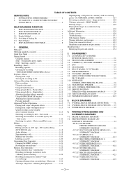
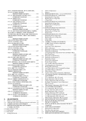
... a tape 1-7 Viewing the recording on a moving picture- Title search 1-16 Searching for voltage measurement and check 2-8 2-14. Photo save 1-26 Viewing a still picture - Memory photo playback 1-26 Superimposing a still picture in a continuous loop -SLIDE SHOW 1-30 Additional Information 1-30 Usable cassettes 1-30 Troubleshooting 1-31 Self-diagnosis display 1-32 Warning indicators and messages 1-32 Using your own titles 1-20 Labeling a cassette 1-20 Customizing Your Camcorder 1-21 Changing the MENU settings 1-21 Resetting the date and time 1-22 Memory Stick Operations...
... a tape 1-7 Viewing the recording on a moving picture- Title search 1-16 Searching for voltage measurement and check 2-8 2-14. Photo save 1-26 Viewing a still picture - Memory photo playback 1-26 Superimposing a still picture in a continuous loop -SLIDE SHOW 1-30 Additional Information 1-30 Usable cassettes 1-30 Troubleshooting 1-31 Self-diagnosis display 1-32 Warning indicators and messages 1-32 Using your own titles 1-20 Labeling a cassette 1-20 Customizing Your Camcorder 1-21 Changing the MENU settings 1-21 Resetting the date and time 1-22 Memory Stick Operations...
Service Manual
Page 4
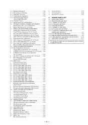
... Setting 5-24 9. Auto White Balance & LV Standard Data Input 5-26 13. COLOR ELECTRONIC VIEWFINDER SYSTEM ADJUSTMENT 5-28 1. Contrast Adjustment (DD-123 board 5-29 4. HOW TO ENTER RECORD MODE WITHOUT CASSETTE 5-35 2-2. Preparation for Adjustment 5-35 2. PREPARATIONS BEFORE ADJUSTMENT (CAMERA SECTION 5-4 1-1-1. INITIALIZATION OF B, C, D, E, F PAGE DATA 5-8 1-2-1. D Page Table 5-11 1-2-3. Initializing the E, F Page Data 5-14 2. CAMERA SYSTEM ADJUSTMENTS 5-19 1. 36 MHz Origin Oscillation Adjustment (VC-217 board 5-19 2. Zoom Key Center Adjustment 5-19 3. LCD...
... Setting 5-24 9. Auto White Balance & LV Standard Data Input 5-26 13. COLOR ELECTRONIC VIEWFINDER SYSTEM ADJUSTMENT 5-28 1. Contrast Adjustment (DD-123 board 5-29 4. HOW TO ENTER RECORD MODE WITHOUT CASSETTE 5-35 2-2. Preparation for Adjustment 5-35 2. PREPARATIONS BEFORE ADJUSTMENT (CAMERA SECTION 5-4 1-1-1. INITIALIZATION OF B, C, D, E, F PAGE DATA 5-8 1-2-1. D Page Table 5-11 1-2-3. Initializing the E, F Page Data 5-14 2. CAMERA SYSTEM ADJUSTMENTS 5-19 1. 36 MHz Origin Oscillation Adjustment (VC-217 board 5-19 2. Zoom Key Center Adjustment 5-19 3. LCD...
Service Manual
Page 5
...S VIDEO OUT Chroma Level Adjustment (VC-217 board 5-45 4. Preparation for recording 5-49 2-2. IC1600 (SFD) BIST (REC) Check 5-49 2-4. IC1601 (TFD) BIST (REC) Check 5-50 2-5. Playback Level Check 5-54 2. Overall Distortion Check 5-54 4. Precautions upon using the adjustment remote commander 5-55 4-2. DATA PROCESS 5-56 4-3. REPAIR PARTS LIST 6-1. EXPLODED VIEWS 6-1 6-1-1. LCD PANEL SECTION 6-3 6-1-4. EVF AND LENS SECTION 6-6 6-1-7. Checking the Input Signals (Except AEP/UK model 5-38 3-1-6. SERVO AND RF SYSTEM ADJUSTMENT 5-41 1. Switching Position Adjustment (VC...
...S VIDEO OUT Chroma Level Adjustment (VC-217 board 5-45 4. Preparation for recording 5-49 2-2. IC1600 (SFD) BIST (REC) Check 5-49 2-4. IC1601 (TFD) BIST (REC) Check 5-50 2-5. Playback Level Check 5-54 2. Overall Distortion Check 5-54 4. Precautions upon using the adjustment remote commander 5-55 4-2. DATA PROCESS 5-56 4-3. REPAIR PARTS LIST 6-1. EXPLODED VIEWS 6-1 6-1-1. LCD PANEL SECTION 6-3 6-1-4. EVF AND LENS SECTION 6-6 6-1-7. Checking the Input Signals (Except AEP/UK model 5-38 3-1-6. SERVO AND RF SYSTEM ADJUSTMENT 5-41 1. Switching Position Adjustment (VC...
Service Manual
Page 7
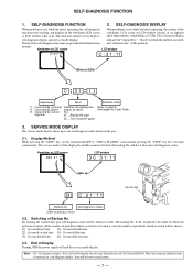
... coin-type lithium battery is operating, the counter of the function starts working, and displays on power again. 3. This function consists of Display Turning OFF the power supply will be lost by service E.g. and the 5-character self-diagnosis codes. Display Method While pressing the "STOP" key, set the switch from OFF to do. End of two display; engineer 31 ....Reload the tape. 32 ....Turn on the viewfinder, LCD screen viewfinder, LCD screen or LCD window consists...
... coin-type lithium battery is operating, the counter of the function starts working, and displays on power again. 3. This function consists of Display Turning OFF the power supply will be lost by service E.g. and the 5-character self-diagnosis codes. Display Method While pressing the "STOP" key, set the switch from OFF to do. End of two display; engineer 31 ....Reload the tape. 32 ....Turn on the viewfinder, LCD screen viewfinder, LCD screen or LCD window consists...
Service Manual
Page 8
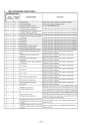
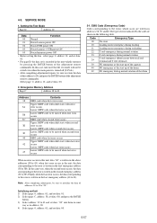
... is rotated in the focus manual mode, and the focus motor drive circuit (IC302 of VC-217 board) when zooming is used. Remove the battery or power cable, connect, and perform operations from the beginning. 2 1 Winding S reel fault when counting the rest of tape. Remove the cassette, and insert it again after one hour. 0 0 Video head is not performed. Load the tape again, and perform operations from the beginning. 2 4 T reel...
... is rotated in the focus manual mode, and the focus motor drive circuit (IC302 of VC-217 board) when zooming is used. Remove the battery or power cable, connect, and perform operations from the beginning. 2 1 Winding S reel fault when counting the rest of tape. Remove the cassette, and insert it again after one hour. 0 0 Video head is not performed. Load the tape again, and perform operations from the beginning. 2 4 T reel...
Service Manual
Page 59
... mode HK: Hong Kong model Note : The components identified by reference number, pleas include the board name. Transistor Diode C 654 456 4 5 1 2 3 3 3 B E 123 321 321 543 21 21 21 (For schematic diagrams) • All capacitors are in this , the necessary note is used.). • Voltage values change depending upon input impedance of (+,-) B LINE. * • C : adjustment for repair. * • Circled numbers...
... mode HK: Hong Kong model Note : The components identified by reference number, pleas include the board name. Transistor Diode C 654 456 4 5 1 2 3 3 3 B E 123 321 321 543 21 21 21 (For schematic diagrams) • All capacitors are in this , the necessary note is used.). • Voltage values change depending upon input impedance of (+,-) B LINE. * • C : adjustment for repair. * • Circled numbers...

Service Manual
Page 91
... because the focus ring and audio/video jack are used for the data on history use (data of page: 2, address: A2 to AA). (Refer to "SELF-DIAGNOSIS FUNCTION" for the self-diagnosis data, and to "5-4.Service Mode" for adjustments. Note 5: Exiting the "Forced Camera Power ON" Mode 1) Select page: 0, address: 01, and set data: 01. 2) Select page: D, address: 10, set data: 00, and press the PAUSE button of the adjustment remote commander. 3) Select...
... because the focus ring and audio/video jack are used for the data on history use (data of page: 2, address: A2 to AA). (Refer to "SELF-DIAGNOSIS FUNCTION" for the self-diagnosis data, and to "5-4.Service Mode" for adjustments. Note 5: Exiting the "Forced Camera Power ON" Mode 1) Select page: 0, address: 01, and set data: 01. 2) Select page: D, address: 10, set data: 00, and press the PAUSE button of the adjustment remote commander. 3) Select...
Service Manual
Page 106
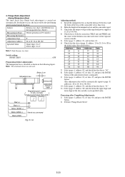
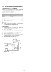
... the exposure screen coincide. 5) Select page: 0, address: 01, and set data: 01. 6) Check that the upper digit and lower digit of the adjustment remote commander. 9) Select page: 6, address: 01, set data: 00, and press the PAUSE button. 2) Perform "Flange Back Check". 5-20 Adjusting method: 1) Install the minipattern box so that the data is less than 3.5A Red (+) Black (-) Yellow (SENS +) White (SENS -) Black (GND) Need not connected Fig. 5-1-6. 4. Address Data Address Data 24 51...
... the exposure screen coincide. 5) Select page: 0, address: 01, and set data: 01. 6) Check that the upper digit and lower digit of the adjustment remote commander. 9) Select page: 6, address: 01, set data: 00, and press the PAUSE button. 2) Perform "Flange Back Check". 5-20 Adjusting method: 1) Install the minipattern box so that the data is less than 3.5A Red (+) Black (-) Yellow (SENS +) White (SENS -) Black (GND) Need not connected Fig. 5-1-6. 4. Address Data Address Data 24 51...
Service Manual
Page 116
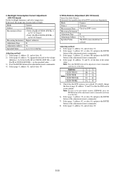
... memory (EEPROM), press the PAUSE button of the adjustment remote commander each time to set the voltage difference (A) between Pin 2 of CN2904 (EVF BL +) and Pin 3 of CN2904 (EVF BL -) to the initial value. 4. Mode Camera Subject Arbitrary Measurement Point Check on EVF screen Measuring Instrument Adjustment Page D Adjustment Address 71, 72 Specified Value The EVF screen should not be colored. If colored, change the data and set the data...
... memory (EEPROM), press the PAUSE button of the adjustment remote commander each time to set the voltage difference (A) between Pin 2 of CN2904 (EVF BL +) and Pin 3 of CN2904 (EVF BL -) to the initial value. 4. Mode Camera Subject Arbitrary Measurement Point Check on EVF screen Measuring Instrument Adjustment Page D Adjustment Address 71, 72 Specified Value The EVF screen should not be colored. If colored, change the data and set the data...
Service Manual
Page 120
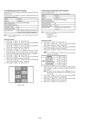
... the PAUSE button of the adjustment remote commander each time to the specified value. Note1 : Perform "Bright Adjustment" and "Contrast Adjustment" before this adjustment. If deviated, the LCD screen color cannot be colored. Light induction plate 3. B A A B B A A B Fig. 5-1-22. 7. Note 1: Check the white balance only when replacing the following parts. If colored, change the data so that the brightness of the section A and that of the section B is not colored. If deviated, the LCD display...
... the PAUSE button of the adjustment remote commander each time to the specified value. Note1 : Perform "Bright Adjustment" and "Contrast Adjustment" before this adjustment. If deviated, the LCD screen color cannot be colored. Light induction plate 3. B A A B B A A B Fig. 5-1-22. 7. Note 1: Check the white balance only when replacing the following parts. If colored, change the data so that the brightness of the section A and that of the section B is not colored. If deviated, the LCD display...

Service Manual
Page 123
... turned on with the power switch block (PS-4550 block) removed. The above procedure will enable the camera power to be connected except during "Battery End Check". Note 3: Setting the "Forced Memory Power ON" mode (Memory mode) 1) Select page: 0, address: 01, and set data: 01. 2) Select page: D, address: 10, set the "Forced VTR Power ON mode" using the adjustment remote commander (Note 2). To set to the VTR mode, set the power switch to "CAMERA" or set menus will enable the memory power...
... turned on with the power switch block (PS-4550 block) removed. The above procedure will enable the camera power to be connected except during "Battery End Check". Note 3: Setting the "Forced Memory Power ON" mode (Memory mode) 1) Select page: 0, address: 01, and set data: 01. 2) Select page: D, address: 10, set the "Forced VTR Power ON mode" using the adjustment remote commander (Note 2). To set to the VTR mode, set the power switch to "CAMERA" or set menus will enable the memory power...
Service Manual
Page 126
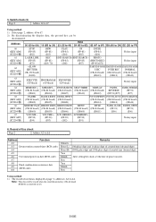
... output voltage of B, C, D, E, F Page Data If the B, C, D, E, F page data is 6.0 ± 0.1Vdc. 2) Turn off the power supply. 3) Turn on the HOLD switch of the adjustment remote commander. 4) Turn on the power supply. 5) Load a cassette, and set to the battery terminal as shown in Fig. 5-3-4. Mode Camera recording Subject Arbitrary Switch setting 1) AUTO FOCUS OFF 2) LCD screen Closed 3) REC LAMP (Menu display ON Connection: 1) Connect the regulated power supply and the digital voltmeter to the camera recording mode. 6) Check that the REC LAMP blinks at 0.8 Hz. SYSTEM CONTROL...
... output voltage of B, C, D, E, F Page Data If the B, C, D, E, F page data is 6.0 ± 0.1Vdc. 2) Turn off the power supply. 3) Turn on the HOLD switch of the adjustment remote commander. 4) Turn on the power supply. 5) Load a cassette, and set to the battery terminal as shown in Fig. 5-3-4. Mode Camera recording Subject Arbitrary Switch setting 1) AUTO FOCUS OFF 2) LCD screen Closed 3) REC LAMP (Menu display ON Connection: 1) Connect the regulated power supply and the digital voltmeter to the camera recording mode. 6) Check that the REC LAMP blinks at 0.8 Hz. SYSTEM CONTROL...

Service Manual
Page 128
... reference tape and enter the VTR STOP mode. 2) Select page: 0, address: 01, and set data: 40. 2) Record the camera signal for 1 to 2 seconds, perform step 4 and higher. 4) Select page: 3, address: 01, set data: 23, and press the PAUSE button of CN2904. 75Ω resistor (Parts code: 1-247-804-11) Adjusting method: 1) Select page: 0, address: 01, and set data: 01. 2) Playback the recorded signal at "Preparations before adjustments Mode Camera recording Subject Arbitrary Adjusting...
... reference tape and enter the VTR STOP mode. 2) Select page: 0, address: 01, and set data: 40. 2) Record the camera signal for 1 to 2 seconds, perform step 4 and higher. 4) Select page: 3, address: 01, set data: 23, and press the PAUSE button of CN2904. 75Ω resistor (Parts code: 1-247-804-11) Adjusting method: 1) Select page: 0, address: 01, and set data: 01. 2) Playback the recorded signal at "Preparations before adjustments Mode Camera recording Subject Arbitrary Adjusting...
Service Manual
Page 135
... for recording 1) Playback the BIST check tape.(XH5-6(NTSC), XH5-6P(PAL)) 2) Select page: 3, address: 10, set data: C0, and press the PAUSE button. 3) Select page: 3, address: 11, set data: 07, and press the PAUSE button. 4) Enter the stop mode. 5) While keep the HOLD switch of the adjusting remote commander at ON(SERVICE) position, eject the BIST check tape and insert a tape for DCR-TRV10/TRV10E model, select page: C, address: 60, and set data: 08, and press the PAUSE button...
... for recording 1) Playback the BIST check tape.(XH5-6(NTSC), XH5-6P(PAL)) 2) Select page: 3, address: 10, set data: C0, and press the PAUSE button. 3) Select page: 3, address: 11, set data: 07, and press the PAUSE button. 4) Enter the stop mode. 5) While keep the HOLD switch of the adjusting remote commander at ON(SERVICE) position, eject the BIST check tape and insert a tape for DCR-TRV10/TRV10E model, select page: C, address: 60, and set data: 08, and press the PAUSE button...

Service Manual
Page 141
... PAUSE button must be pressed to FF. • Changing the data (Data setting) The data increases when the PLAY (() button is pressed, and decreases when the STOP (p) button is not performed.) 4) After completing all adjustment data be recorded in the non-volatile memory. 1. The adjustment remote commander performs bi-directional communication with the unit using the adjustment remote commander Mishandling of the adjustment remote commander may erase the correct adjustment data at times. Page Data Address Fig. 5-4-1 3) Operate the adjustment remote...
... PAUSE button must be pressed to FF. • Changing the data (Data setting) The data increases when the PLAY (() button is pressed, and decreases when the STOP (p) button is not performed.) 4) After completing all adjustment data be recorded in the non-volatile memory. 1. The adjustment remote commander performs bi-directional communication with the unit using the adjustment remote commander Mishandling of the adjustment remote commander may erase the correct adjustment data at times. Page Data Address Fig. 5-4-1 3) Operate the adjustment remote...
Service Manual
Page 143
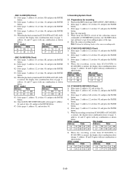
... non-volatile memory by the code are written in the following table. 4-3. Setting the Test Mode Page D Address 10 Data Function 00 Normal 01 Forced camera power ON 02 Forced VTR power ON 03 Forced camera + VTR power ON 05 Forced memory power ON • Before setting the data , select page: 0, address: 01, and set data: 01. • For page D, the data set data: 00. 2. Code Emergency Type 00 No error 10 Loading...
... non-volatile memory by the code are written in the following table. 4-3. Setting the Test Mode Page D Address 10 Data Function 00 Normal 01 Forced camera power ON 02 Forced VTR power ON 03 Forced camera + VTR power ON 05 Forced memory power ON • Before setting the data , select page: 0, address: 01, and set data: 01. • For page D, the data set data: 00. 2. Code Emergency Type 00 No error 10 Loading...
Service Manual
Page 146
... input 64 (KEY AD4) (IC2204 (¶) MEMORY + MEMORY - Using method: 1) The record of power on date (BCD code) A7 A8 Final condensation occurrence date A9 (BCD code) AA Minutes Hour (L) Hour (H) Year Month Day Year Month Day Remarks 10th place digit and 1st place digit of counted time (decimal digit) 1000th place digit and 100th place digit of counted time (decimal digit) After setting the clock, set the date of use data is removed (reset...
... input 64 (KEY AD4) (IC2204 (¶) MEMORY + MEMORY - Using method: 1) The record of power on date (BCD code) A7 A8 Final condensation occurrence date A9 (BCD code) AA Minutes Hour (L) Hour (H) Year Month Day Year Month Day Remarks 10th place digit and 1st place digit of counted time (decimal digit) 1000th place digit and 100th place digit of counted time (decimal digit) After setting the clock, set the date of use data is removed (reset...
Service Manual
Page 157
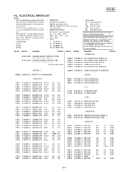
... or dotted line with part number specified. Description Remarks A-...Part No. Part No. • Abbreviation AUS: Australian model JE: Tourist model CND: Canadian model CN: Chinese mode HK: Hong Kong model When indicating parts...used on the set. Replace only with mark ! In each case, u: µ, for safety. uPB... , µPB... , uPC... , µPC... , Some delay should be different from the original • SEMICONDUCTORS one. ordering these items. • Model • CAPACITORS: 8: DCR-TRV8 uF: µF 8E: DCR-TRV8E • COILS 10: DCR-TRV10 uH: µH 10E: DCR...
... or dotted line with part number specified. Description Remarks A-...Part No. Part No. • Abbreviation AUS: Australian model JE: Tourist model CND: Canadian model CN: Chinese mode HK: Hong Kong model When indicating parts...used on the set. Replace only with mark ! In each case, u: µ, for safety. uPB... , µPB... , uPC... , µPC... , Some delay should be different from the original • SEMICONDUCTORS one. ordering these items. • Model • CAPACITORS: 8: DCR-TRV8 uF: µF 8E: DCR-TRV8E • COILS 10: DCR-TRV10 uH: µH 10E: DCR...


