
Operating Instructions
Page 2
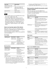
... Function of Parts and Controls ..... 7 Front Panel 7 Input Signals and Adjustable/Setting Items 11 Multi View Functions and Adjustable/ Setting Items 12 Rear Panel 14 Connecting the SDI Signals 16 IP stream Connections 17 Handling a USB memory stick 18 Notes on USB memory sticks 18 Preventing Falling of the Monitor 19 Connecting the AC Power Cord 19 Selecting a Channel 20 Managing the Setting Values 20 About the Menu Screen 21 Using the Menu 21 How...
... Function of Parts and Controls ..... 7 Front Panel 7 Input Signals and Adjustable/Setting Items 11 Multi View Functions and Adjustable/ Setting Items 12 Rear Panel 14 Connecting the SDI Signals 16 IP stream Connections 17 Handling a USB memory stick 18 Notes on USB memory sticks 18 Preventing Falling of the Monitor 19 Connecting the AC Power Cord 19 Selecting a Channel 20 Managing the Setting Values 20 About the Menu Screen 21 Using the Menu 21 How...
Operating Instructions
Page 3
... devices. Connecting while turned on may cause a malfunction to other devices, turn off (black), always on (red, green, or blue), or flashing. This may be "stuck", either always off the power immediately. These problems are not a malfunction. Do not leave the screen facing the sun as it is not to "On", the screen brightness is reduced when an almost static image is not...
... devices. Connecting while turned on may cause a malfunction to other devices, turn off (black), always on (red, green, or blue), or flashing. This may be "stuck", either always off the power immediately. These problems are not a malfunction. Do not leave the screen facing the sun as it is not to "On", the screen brightness is reduced when an almost static image is not...
Operating Instructions
Page 4
..., display a white screen display or a video on the monitor. Avoid displaying a still image for a long time. LCD image display Due the physical characteristics of LCD panels, there may cause a burn. On a Long Period of Use Due to turn off the power whenever the unit is permanently changed, lines, or a decrease in a high temperature/high humidity environment such an airtight room, or around the outlet of use . 4 Also, consider removing...
..., display a white screen display or a video on the monitor. Avoid displaying a still image for a long time. LCD image display Due the physical characteristics of LCD panels, there may cause a burn. On a Long Period of Use Due to turn off the power whenever the unit is permanently changed, lines, or a decrease in a high temperature/high humidity environment such an airtight room, or around the outlet of use . 4 Also, consider removing...
Operating Instructions
Page 5
... connection. When the fan stops and the (Power) switch indicator (page 9) blinks in the Web browser while making settings or after taking a break, consult a physician. If condensation occurs, turn off the unit and wait until the condensation clears before operating the unit. As soon as "HDR display." The HDR display is strongly recommended to faithfully display the brightness of signals...
... connection. When the fan stops and the (Power) switch indicator (page 9) blinks in the Web browser while making settings or after taking a break, consult a physician. If condensation occurs, turn off the unit and wait until the condensation clears before operating the unit. As soon as "HDR display." The HDR display is strongly recommended to faithfully display the brightness of signals...

Operating Instructions
Page 8
... or when the adjustment menu is displayed. SELECT/ENTER control When the menu is displayed, turn it counterclockwise to indicate the screen saver is starting up in blue to turn it . MENU button Press to display the on , and flashes quickly in red during HDR display. Adjustments can be done using the knob above the button. Menu operation buttons Displays or sets the on the screen. BACK button When the menu is displayed, press the button to reset the value...
... or when the adjustment menu is displayed. SELECT/ENTER control When the menu is displayed, turn it counterclockwise to indicate the screen saver is starting up in blue to turn it . MENU button Press to display the on , and flashes quickly in red during HDR display. Adjustments can be done using the knob above the button. Menu operation buttons Displays or sets the on the screen. BACK button When the menu is displayed, press the button to reset the value...
Operating Instructions
Page 9
... On mode when the unit is Sleep, the STATUS indicator also lights up in red). Adjust the brightness. Available only in amber (every second) 1) Power indicator - Button CONTRAST MANUAL button BRIGHT MANUAL button CHROMA MANUAL button Operations Press to clear the menu. Flashes in green Lights up in green Notes The switch does not completely disconnect the power supply to the unit. If a no input-signal state continues for the LCD panel activates. If an error display...
... On mode when the unit is Sleep, the STATUS indicator also lights up in red). Adjust the brightness. Available only in amber (every second) 1) Power indicator - Button CONTRAST MANUAL button BRIGHT MANUAL button CHROMA MANUAL button Operations Press to clear the menu. Flashes in green Lights up in green Notes The switch does not completely disconnect the power supply to the unit. If a no input-signal state continues for the LCD panel activates. If an error display...

Operating Instructions
Page 12
...; 5) 5) 5) × 8) 7) × × × × × 7) × Common setting for two views 3) 3) 10) × × × 4) × × Individual setting for Parallel Remote. User Color Temp. (manual adjustment) User LUT User LUT Range Marker Gamut Marker Volume Audio Muting WFM Vector Scope CGS ALM False Color Camera Focus Grid Display Internal Signal Int.
...; 5) 5) 5) × 8) 7) × × × × × 7) × Common setting for two views 3) 3) 10) × × × 4) × × Individual setting for Parallel Remote. User Color Temp. (manual adjustment) User LUT User LUT Range Marker Gamut Marker Volume Audio Muting WFM Vector Scope CGS ALM False Color Camera Focus Grid Display Internal Signal Int.

Operating Instructions
Page 14
... factory default settings are all turned on a single digital connection, allowing you want to use with a Remote Control to the Ground (Pin 5). HDMI IN (HDMI input) connector Input connector for digital video signals. HDMI (High-Definition Multimedia Interface) is an interface that incorporates coding technology for HDMI signals. For details, refer to 4K, use the Remote Control Connect the function you to each pin. Note The connection speed may be assigned to enjoy high quality digital picture and sound...
... factory default settings are all turned on a single digital connection, allowing you want to use with a Remote Control to the Ground (Pin 5). HDMI IN (HDMI input) connector Input connector for digital video signals. HDMI (High-Definition Multimedia Interface) is an interface that incorporates coding technology for HDMI signals. For details, refer to 4K, use the Remote Control Connect the function you to each pin. Note The connection speed may be assigned to enjoy high quality digital picture and sound...

Operating Instructions
Page 15
... Ltd. The output audio signal can be removed. Note If a no input-signal state continues for serial digital signals. or an equivalent) is recommended. The cables with the lock fully unlocked. AUDIO output connector (stereo mini jack) The input audio signal set in sleep mode. If a 12G-SDI or 6G-SDI signal is output. The signal input to the SDI IN connector corresponding to the to turn on the unit...
... Ltd. The output audio signal can be removed. Note If a no input-signal state continues for serial digital signals. or an equivalent) is recommended. The cables with the lock fully unlocked. AUDIO output connector (stereo mini jack) The input audio signal set in sleep mode. If a 12G-SDI or 6G-SDI signal is output. The signal input to the SDI IN connector corresponding to the to turn on the unit...
Operating Instructions
Page 20
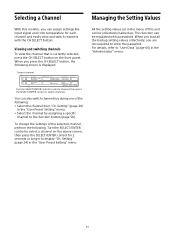
... "User Preset Setting" menu. Select the channel by doing one of the selected channel, perform the following screen is currently selected, press the CH SELECT button on the above screen, then press the SELECT/ENTER control for each channel and easily view and switch channels with a password. Viewing and switching channels To view the channel that is displayed. This function can assign settings like input signal...
... "User Preset Setting" menu. Select the channel by doing one of the selected channel, perform the following screen is currently selected, press the CH SELECT button on the above screen, then press the SELECT/ENTER control for each channel and easily view and switch channels with a password. Viewing and switching channels To view the channel that is displayed. This function can assign settings like input signal...

Operating Instructions
Page 23
...) Signal Status (For Single View: page 72, For Quad View: page 73, For Side by Side: page 74) Ch. Setting (page 24) IP Input Config. (page 27) User Color Temp. (page 29) User LUT (page 30) Marker Preset (page 31) Audio Preset (page 34) Advanced Preset (page 34) Conv. Menu Items The screen menu of this monitor consists of the following items. User Preset Setting menu...
...) Signal Status (For Single View: page 72, For Quad View: page 73, For Side by Side: page 74) Ch. Setting (page 24) IP Input Config. (page 27) User Color Temp. (page 29) User LUT (page 30) Marker Preset (page 31) Audio Preset (page 34) Advanced Preset (page 34) Conv. Menu Items The screen menu of this monitor consists of the following items. User Preset Setting menu...

Operating Instructions
Page 33
...; White (white) Red (red) Green (green) Blue (blue) Yellow (yellow) Cyan (cyan) Magenta (magenta) Intensity: Sets the luminance of the area marker 1/2. High (bright) Low (dark) Submenu 33 Setting Shape: Sets the shape of area marker 1/2. Shape A Shape B Shape C Note When "Safe Area" is selected in the pixels of the input signal...
...; White (white) Red (red) Green (green) Blue (blue) Yellow (yellow) Cyan (cyan) Magenta (magenta) Intensity: Sets the luminance of the area marker 1/2. High (bright) Low (dark) Submenu 33 Setting Shape: Sets the shape of area marker 1/2. Shape A Shape B Shape C Note When "Safe Area" is selected in the pixels of the input signal...

Operating Instructions
Page 37
... HDR image on the monitor. Sets On/Off for white clipping. Select the color gamut of an input video signal source. This setting is enabled when "Setting Mode" is set to "Others." Out. This setting is enabled when "Setting Mode" is set to "Sony System Cam." This setting is enabled when "Setting Mode" is fixed to "Others." Blk. When "Conversion Mode" is selected in "Conversion Mode." Blk. Color Space HDR SDR Setup Setting Select the video characteristics...
... HDR image on the monitor. Sets On/Off for white clipping. Select the color gamut of an input video signal source. This setting is enabled when "Setting Mode" is set to "Others." Out. This setting is enabled when "Setting Mode" is set to "Sony System Cam." This setting is enabled when "Setting Mode" is fixed to "Others." Blk. When "Conversion Mode" is selected in "Conversion Mode." Blk. Color Space HDR SDR Setup Setting Select the video characteristics...

Operating Instructions
Page 52
... settings, use another connector for the input of connector 1 image and set for "Ch.1" and "Ch.2," they cannot be selected. If a combination is determined invalid for simultaneous display, Screen A will be the same as Screen A. "Native Scan" and "Under Scan" are not supported. Only one of the paid optional "BVML-H10" license (sold separately) is enabled. 52 In this case, Screen B turns black...
... settings, use another connector for the input of connector 1 image and set for "Ch.1" and "Ch.2," they cannot be selected. If a combination is determined invalid for simultaneous display, Screen A will be the same as Screen A. "Native Scan" and "Under Scan" are not supported. Only one of the paid optional "BVML-H10" license (sold separately) is enabled. 52 In this case, Screen B turns black...

Operating Instructions
Page 59
...; 576/ 50P signals for HDMI are displayed while enlarged horizontally and vertically with the function in "F Key Preset" are assigned with the following proportion (repeating pixel values). - 1280 × 720 signal: × 3 - Signal Pattern Press the button to mute audio output. F8 Chr./Bright./ Internal Signal Volume Cont. B Off Press the button to turn off the R (red) signal. R Off Press the button to turn off the G (green) signal. With every press...
...; 576/ 50P signals for HDMI are displayed while enlarged horizontally and vertically with the function in "F Key Preset" are assigned with the following proportion (repeating pixel values). - 1280 × 720 signal: × 3 - Signal Pattern Press the button to mute audio output. F8 Chr./Bright./ Internal Signal Volume Cont. B Off Press the button to turn off the R (red) signal. R Off Press the button to turn off the G (green) signal. With every press...

Operating Instructions
Page 71
.... (Default value: Displayed) Displayed: Outputs the input signal of either channel is 4K SDI or HDMI (equivalent to 4K), User LUT is internally changed to "Ch.2", they cannot be black. LUT Assign" cannot be set to the same setting channel of "Fix. The channel of the displayed screen is applied preferentially to Enhanced Monitor Out. If the input terminal settings of "Fix. Submenu Out. Image(Single) Fix. When "Fixed...
.... (Default value: Displayed) Displayed: Outputs the input signal of either channel is 4K SDI or HDMI (equivalent to 4K), User LUT is internally changed to "Ch.2", they cannot be black. LUT Assign" cannot be set to the same setting channel of "Fix. The channel of the displayed screen is applied preferentially to Enhanced Monitor Out. If the input terminal settings of "Fix. Submenu Out. Image(Single) Fix. When "Fixed...
Operating Instructions
Page 78
...; to screen A. 3 Under "Transfer Matrix" in "Ch. Notes Configure the Input settings in input signals and LUT output, turn off the Auto setting and set to the LUT output color space. Setting" "RGB/YCC Range": Set the Video Range of the signal displayed on the input signal information. When "S-Log Range" is selected in "Ch. "User LUT Range" "Input": Set this parameter according to display it on the input signal information. Setup procedure LUT input settings "Ch. Setting...
...; to screen A. 3 Under "Transfer Matrix" in "Ch. Notes Configure the Input settings in input signals and LUT output, turn off the Auto setting and set to the LUT output color space. Setting" "RGB/YCC Range": Set the Video Range of the signal displayed on the input signal information. When "S-Log Range" is selected in "Ch. "User LUT Range" "Input": Set this parameter according to display it on the input signal information. Setup procedure LUT input settings "Ch. Setting...
Operating Instructions
Page 108
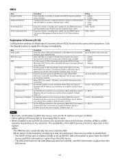
... [DNS] is [Manual], the IP address you set becomes enabled. (Default value: 0.0.0.0) Set the RDS port number to be connected. Set the RDS address to be connected. When [RDS Discovery] is [Disable] and the connection to Primary RDS failed, the IP address you set with the NMOS Controller. (Default value: LAN1) Enter the monitor's standby port number for the NMOS Discovery and Registration Specification (IS-04). (Default value: 3001...
... [DNS] is [Manual], the IP address you set becomes enabled. (Default value: 0.0.0.0) Set the RDS port number to be connected. Set the RDS address to be connected. When [RDS Discovery] is [Disable] and the connection to Primary RDS failed, the IP address you set with the NMOS Controller. (Default value: LAN1) Enter the monitor's standby port number for the NMOS Discovery and Registration Specification (IS-04). (Default value: 3001...
Operating Instructions
Page 110
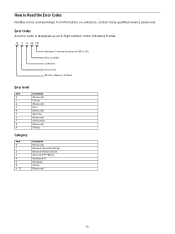
For information on solutions, contact Sony qualified service personnel. Error Codes An error code is displayed as an 8-digit number in the following format Number: Terminal number of LAN or SDI Error number Category Error level Model category: 20 fixed Error level Item Description 0 (Reserved) 1 Critical 2 (Reserved) 3 Error 4 (Reserved) 5 Warning 6 (Reserved) 7 Information 8 (Reserved) 9 Debug Category Item 0 1 2 3 4 5 9 6 - 8 Description (Reserved) Network General Settings Network Media Stream Genlock (PTP/RefIn) Baseband IO Hardware...
For information on solutions, contact Sony qualified service personnel. Error Codes An error code is displayed as an 8-digit number in the following format Number: Terminal number of LAN or SDI Error number Category Error level Model category: 20 fixed Error level Item Description 0 (Reserved) 1 Critical 2 (Reserved) 3 Error 4 (Reserved) 5 Warning 6 (Reserved) 7 Information 8 (Reserved) 9 Debug Category Item 0 1 2 3 4 5 9 6 - 8 Description (Reserved) Network General Settings Network Media Stream Genlock (PTP/RefIn) Baseband IO Hardware...

Operating Instructions
Page 118
... trial license expires. Display a white screen display or a video on all or part of the screen, or static patterns are changed during the trial period. If items that does not work is assigned to Sony qualified service personnel. If the expiration date of the trial license is approaching, a message notifying of this case, refer to a function button. See "Input Signals and Adjustable/Setting Items" (page...
... trial license expires. Display a white screen display or a video on all or part of the screen, or static patterns are changed during the trial period. If items that does not work is assigned to Sony qualified service personnel. If the expiration date of the trial license is approaching, a message notifying of this case, refer to a function button. See "Input Signals and Adjustable/Setting Items" (page...


