
Operation Manual
Page 2
..., 1:53 PM Model No.: XV-Z12000 Serial No.: There are two important reasons for prompt warranty registration of your new SHARP Projector, using the projector, please read this equip- REFER SERVICING TO QUALIFIED SERVICE PERSONNEL. Before recycling the packaging, please be required to operate this ... Safety Act, PLEASE READ CAREFULLY THE IMPORTANT "LIMITED WARRANTY" CLAUSE. CONSUMER PRODUCT SAFETY ACT To ensure that SHARP may be of the projector and retain this product to persons. Introduction Before using the REGISTRATION CARD packed with arrowhead symbol, within the product...
..., 1:53 PM Model No.: XV-Z12000 Serial No.: There are two important reasons for prompt warranty registration of your new SHARP Projector, using the projector, please read this equip- REFER SERVICING TO QUALIFIED SERVICE PERSONNEL. Before recycling the packaging, please be required to operate this ... Safety Act, PLEASE READ CAREFULLY THE IMPORTANT "LIMITED WARRANTY" CLAUSE. CONSUMER PRODUCT SAFETY ACT To ensure that SHARP may be of the projector and retain this product to persons. Introduction Before using the REGISTRATION CARD packed with arrowhead symbol, within the product...
Operation Manual
Page 3
...-XVZ100005 WARNING: Some IC chips in this device must accept any interference received, including interference that may cause harmful interference to Part 15 of Conformity SHARP PROJECTOR, MODEL XV-Z12000 This device complies with the operation manual, may cause undesired operation. Operation is encouraged to try to correct the interference by one...
...-XVZ100005 WARNING: Some IC chips in this device must accept any interference received, including interference that may cause harmful interference to Part 15 of Conformity SHARP PROJECTOR, MODEL XV-Z12000 This device complies with the operation manual, may cause undesired operation. Operation is encouraged to try to correct the interference by one...
Operation Manual
Page 4
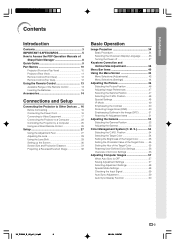
...Introduction Contents 3 IMPORTANT SAFEGUARDS 5 How to Access the PDF Operation Manuals of SharpVision Manager 8 Quick Guide 9 Part Names 10 Projector (Front and Top View 10 Projector (Rear View 11 Remote Control (Front View 12 Remote Control (Top View 12 Using the Remote Control 13 Available Range of... Other Devices ... 16 Before Connecting 16 Connecting the Power Cord 16 Connecting to Video Equipment 17 Connecting the Projector to a Computer 22 Controlling the Projector by a Computer 25 Using as a Wired Remote Control 26 Setup 27 Using the Adjustment Feet 27 Adjusting the Lens...
...Introduction Contents 3 IMPORTANT SAFEGUARDS 5 How to Access the PDF Operation Manuals of SharpVision Manager 8 Quick Guide 9 Part Names 10 Projector (Front and Top View 10 Projector (Rear View 11 Remote Control (Front View 12 Remote Control (Top View 12 Using the Remote Control 13 Available Range of... Other Devices ... 16 Before Connecting 16 Connecting the Power Cord 16 Connecting to Video Equipment 17 Connecting the Projector to a Computer 22 Controlling the Projector by a Computer 25 Using as a Wired Remote Control 26 Setup 27 Using the Adjustment Feet 27 Adjusting the Lens...

Operation Manual
Page 8
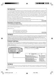
... by an Authorized SharpVision Service Center or Dealer. Place the projector where the intake and exhaust vents are not obstructed. In case of the projector from -4°F to 140°F (-20°C to maintain high image qual- ity, SHARP recommends that it . I For minimal servicing and to +60... outlet and wait at least 11.8" (30 cm) of 5 degrees. See "Replacing the Lamp" on page 78 for replacement. Before moving the projector, be tilted to it is regularly cleaned, use in direct sunlight or room light. I When connecting a computer or other cables connected to a ...
... by an Authorized SharpVision Service Center or Dealer. Place the projector where the intake and exhaust vents are not obstructed. In case of the projector from -4°F to 140°F (-20°C to maintain high image qual- ity, SHARP recommends that it . I For minimal servicing and to +60... outlet and wait at least 11.8" (30 cm) of 5 degrees. See "Replacing the Lamp" on page 78 for replacement. Before moving the projector, be tilted to it is regularly cleaned, use in direct sunlight or room light. I When connecting a computer or other cables connected to a ...

Operation Manual
Page 9
.... Note • The installer of SharpVision Manager may start Acrobat Reader first, then specify the desired file using Acrobat Reader for the "SharpVision Manager" theater projector software provided are included in this operation manual. -8 XV_Z12000_E_US_p05_14.p65 8 03.11.17, 16:37PM For Macintosh: 1 Insert the CD-ROM in the CDROM drive...
.... Note • The installer of SharpVision Manager may start Acrobat Reader first, then specify the desired file using Acrobat Reader for the "SharpVision Manager" theater projector software provided are included in this operation manual. -8 XV_Z12000_E_US_p05_14.p65 8 03.11.17, 16:37PM For Macintosh: 1 Insert the CD-ROM in the CDROM drive...

Operation Manual
Page 10
...the audio equipment using on the video equipment. To video out- Connect the output terminal of the video equipment to the input terminal of the projector and the video equipment is explained as to select the INPUT 4 mode. (Page 35) "On-screen Display 8. Adjust the image size, ...image position and the focus. (Page 28, 29) Adjust the focus by moving the zoom knob. Place the projector facing a wall or a screen. 2. Turn on the remote control. (Page 34) ON button INPUT 4 button The power indicator illuminates blue. Play the video....
...the audio equipment using on the video equipment. To video out- Connect the output terminal of the video equipment to the input terminal of the projector and the video equipment is explained as to select the INPUT 4 mode. (Page 35) "On-screen Display 8. Adjust the image size, ...image position and the focus. (Page 28, 29) Adjust the focus by moving the zoom knob. Place the projector facing a wall or a screen. 2. Turn on the remote control. (Page 34) ON button INPUT 4 button The power indicator illuminates blue. Play the video....

Operation Manual
Page 11
... place. • Press on the two buttons of the lens cap and attach it on . 37 STANDBY button For putting the projector into the standby mode. 78 Temperature warning indicator When the internal temperature rises, this operation manual, the illustration and the screen display...indicator Illuminates blue, indicating normal function. Replace the lamp when the indicator illuminates red. 34 Power indicator Illuminates red, when the projector is explained. Projector (Front and Top View) Adjustment buttons 43 For selecting menu items. ENTER button 43 For setting items selected or adjusted on ...
... place. • Press on the two buttons of the lens cap and attach it on . 37 STANDBY button For putting the projector into the standby mode. 78 Temperature warning indicator When the internal temperature rises, this operation manual, the illustration and the screen display...indicator Illuminates blue, indicating normal function. Replace the lamp when the indicator illuminates red. 34 Power indicator Illuminates red, when the projector is explained. Projector (Front and Top View) Adjustment buttons 43 For selecting menu items. ENTER button 43 For setting items selected or adjusted on ...

Operation Manual
Page 12
... the Terminal Cover 1 Align the hook on the terminal cover with the insert hole in the hook at the back of the projector. 2 Press the hook in the direction indicated with the system for component and RGB signals. Refer to the information that came with... mounted or ceiling mounted, attach the terminal cover (supplied) to the outside with an S-video terminal. 25 RS-232C terminal For controlling projector using a computer. Introduction Projector (Rear View) INPUT 1 terminals 18 Terminals for instructions on how to use with a Kensington MicroSaver Security System. AC socket 16 17 ...
... the Terminal Cover 1 Align the hook on the terminal cover with the insert hole in the hook at the back of the projector. 2 Press the hook in the direction indicated with the system for component and RGB signals. Refer to the information that came with... mounted or ceiling mounted, attach the terminal cover (supplied) to the outside with an S-video terminal. 25 RS-232C terminal For controlling projector using a computer. Introduction Projector (Rear View) INPUT 1 terminals 18 Terminals for instructions on how to use with a Kensington MicroSaver Security System. AC socket 16 17 ...

Operation Manual
Page 13
..."MEDIUM MODE" and "HIGH CONTRAST MODE". Backlight button For lighting all buttons on the remote control. 26 WIRED R/C JACK For controlling the projector by connecting the remote control to a computer. KEYSTONE button 38 For adjusting Keystone Correction or Vertical Size setting. AUTO SYNC button 59 For ...automatically adjusting images when connected to the projector. 03.9.26, 6:35 PM RGB/COMP. Part Names Remote Control (Front View) STANDBY button 37 For putting the projector into the standby mode. button 69 For switching to the default settings. UNDO...
..."MEDIUM MODE" and "HIGH CONTRAST MODE". Backlight button For lighting all buttons on the remote control. 26 WIRED R/C JACK For controlling the projector by connecting the remote control to a computer. KEYSTONE button 38 For adjusting Keystone Correction or Vertical Size setting. AUTO SYNC button 59 For ...automatically adjusting images when connected to the projector. 03.9.26, 6:35 PM RGB/COMP. Part Names Remote Control (Front View) STANDBY button 37 For putting the projector into the standby mode. button 69 For switching to the default settings. UNDO...

Operation Manual
Page 14
... opening, and lower the cover until it clicks in place. Battery fluid from the remote control once they have run out, as possible with this projector may malfunction under a fluorescent lamp. Incorrect use of the batteries may differ due to the screen material. 23'(7 m) 30˚ 45˚ 30&#...cause them to leak. Using the Remote Control Introduction Available Range of the Remote Control I The remote control can be used to control the projector within the ranges shown in the package. 1 Pull down the tab on how they are included in the illustration. Be sure to replace them...
... opening, and lower the cover until it clicks in place. Battery fluid from the remote control once they have run out, as possible with this projector may malfunction under a fluorescent lamp. Incorrect use of the batteries may differ due to the screen material. 23'(7 m) 30˚ 45˚ 30&#...cause them to leak. Using the Remote Control Introduction Available Range of the Remote Control I The remote control can be used to control the projector within the ranges shown in the package. 1 Pull down the tab on how they are included in the illustration. Be sure to replace them...

Operation Manual
Page 17
...digital television system in the supplied power cord into the AC socket on the rear of the projector. This projector can be connected to: Video equipment: I A VCR, DVD player or other devices. Connecting the Projector to Other Devices Before Connecting Note • Before connecting, be sure to unplug the power ...cord of the projector from the AC outlet and turn on the projector and then the other video equipment (See page 17.) I An RS-232C cable (See page 25.) Connecting the Power Cord Plug in...
...digital television system in the supplied power cord into the AC socket on the rear of the projector. This projector can be connected to: Video equipment: I A VCR, DVD player or other devices. Connecting the Projector to Other Devices Before Connecting Note • Before connecting, be sure to unplug the power ...cord of the projector from the AC outlet and turn on the projector and then the other video equipment (See page 17.) I An RS-232C cable (See page 25.) Connecting the Power Cord Plug in...

Operation Manual
Page 18
... S-video output terminal. To view a higher-quality image, use a commercially available S-video cable to connect the INPUT 3 terminal on the projector and the S-video output terminal on the video equipment. VCR or other video equipment can be connected to INPUT 3 or INPUT 4 input ...terminal. 1 Connect an S-video cable or a composite video cable to the projector. • S-video cable: to INPUT 3 terminal • Composite video cable: to INPUT 4 terminal S-video cable (commercially available) *Use when connecting...
... S-video output terminal. To view a higher-quality image, use a commercially available S-video cable to connect the INPUT 3 terminal on the projector and the S-video output terminal on the video equipment. VCR or other video equipment can be connected to INPUT 3 or INPUT 4 input ...terminal. 1 Connect an S-video cable or a composite video cable to the projector. • S-video cable: to INPUT 3 terminal • Composite video cable: to INPUT 4 terminal S-video cable (commercially available) *Use when connecting...

Operation Manual
Page 19
... the video equipment in this way, select "Component" for "Signal Type" in the United States. 1 Connect a component cable to the projector. 2 Connect the above cable to the component video equipment. See page 69. • Set the "Resolution" of "Special Modes" to ...cable (commercially available) To analog component output terminal DVD player or DTV* decoder -18 XV_Z12000_E_US_p15_26.p65 18 03.9.26, 6:36 PM Connecting the Projector to Other Devices Connecting to Component Video Equipment Using a Component Cable (INPUT 1 or 2) Use a component cable when connecting the component video ...
... the video equipment in this way, select "Component" for "Signal Type" in the United States. 1 Connect a component cable to the projector. 2 Connect the above cable to the component video equipment. See page 69. • Set the "Resolution" of "Special Modes" to ...cable (commercially available) To analog component output terminal DVD player or DTV* decoder -18 XV_Z12000_E_US_p15_26.p65 18 03.9.26, 6:36 PM Connecting the Projector to Other Devices Connecting to Component Video Equipment Using a Component Cable (INPUT 1 or 2) Use a component cable when connecting the component video ...

Operation Manual
Page 20
... the thumbscrews. Please refer to the operation manual of the DTV decoder connected to this way, select "A. Note • When connecting the projector to the video equipment in the "Options" menu, or select the RGB mode by pressing on the remote control. XV_Z12000_E_US_p15_26.p65 19 To ...Connect the above cable to the RGB video equipment. RGB" for "Signal Type" in the United States. 1 Connect a 5 RCA RGB cable to the projector. 2 Connect the above cable to the RGB video equipment. • Secure the connectors by pressing on the remote control. See page 69. • The...
... the thumbscrews. Please refer to the operation manual of the DTV decoder connected to this way, select "A. Note • When connecting the projector to the video equipment in the "Options" menu, or select the RGB mode by pressing on the remote control. XV_Z12000_E_US_p15_26.p65 19 To ...Connect the above cable to the RGB video equipment. RGB" for "Signal Type" in the United States. 1 Connect a 5 RCA RGB cable to the projector. 2 Connect the above cable to the RGB video equipment. • Secure the connectors by pressing on the remote control. See page 69. • The...

Operation Manual
Page 21
...-pin D-sub cable (sold separately) To analog component output terminal DVD player or DTV* decoder -20 XV_Z12000_E_US_p15_26.p65 20 03.9.26, 6:37 PM Connecting the Projector to Other Devices Connecting to Component Video Equipment Using a 3 RCA to 15-pin D-sub Cable and the DVI to 15-pin D-sub Adaptor (INPUT 5) Use... is the umbrella term used to describe the new digital television system in the United States. 1 Connect a DVI to 15-pin D-sub adaptor to the projector. 2 Connect a 3 RCA to 15-pin D-
...-pin D-sub cable (sold separately) To analog component output terminal DVD player or DTV* decoder -20 XV_Z12000_E_US_p15_26.p65 20 03.9.26, 6:37 PM Connecting the Projector to Other Devices Connecting to Component Video Equipment Using a 3 RCA to 15-pin D-sub Cable and the DVI to 15-pin D-sub Adaptor (INPUT 5) Use... is the umbrella term used to describe the new digital television system in the United States. 1 Connect a DVI to 15-pin D-sub adaptor to the projector. 2 Connect a 3 RCA to 15-pin D-

Operation Manual
Page 22
...equipment. Connecting to Video Equipment with the DVI output terminal such as DVD players to INPUT 5 terminal. 1 Connect a DVI to HDMI cable to the projector. • Secure the connectors by tightening the thumbscrews. Connecting to Video Equipment with the DVI Output Terminal Using a DVI Cable (INPUT 5) Use a ... video equipment such as DVD players to INPUT 5 terminal. 1 Connect a DVI cable to unplug the power cord of the projector from the AC outlet and turn on the projector and then the other devices. See page 69. • Before connecting, be sure to the pro- Note • Select...
...equipment. Connecting to Video Equipment with the DVI output terminal such as DVD players to INPUT 5 terminal. 1 Connect a DVI to HDMI cable to the projector. • Secure the connectors by tightening the thumbscrews. Connecting to Video Equipment with the DVI Output Terminal Using a DVI Cable (INPUT 5) Use a ... video equipment such as DVD players to INPUT 5 terminal. 1 Connect a DVI cable to unplug the power cord of the projector from the AC outlet and turn on the projector and then the other devices. See page 69. • Before connecting, be sure to the pro- Note • Select...
Operation Manual
Page 23
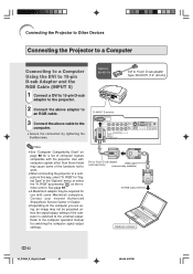
...Dealer. • Depending on the computer you are using, an image may cause some Macintosh computers. Use with some of computer signals compatible with the projector. Refer to the computer operation manual for "Signal Type" in this way, select "A. Optional accessory To INPUT 5 terminal DVI to 15-pin D-sub... a Computer Using the DVI to 15-pin D-sub Adaptor and the RGB Cable (INPUT 5) 1 Connect a DVI to 15-pin D-sub adaptor to the projector. 2 Connect the above adaptor to an RGB cable. 3 Connect the above cable to the computer. • Secure the connectors by pressing on page 88 ...
...Dealer. • Depending on the computer you are using, an image may cause some Macintosh computers. Use with some of computer signals compatible with the projector. Refer to the computer operation manual for "Signal Type" in this way, select "A. Optional accessory To INPUT 5 terminal DVI to 15-pin D-sub... a Computer Using the DVI to 15-pin D-sub Adaptor and the RGB Cable (INPUT 5) 1 Connect a DVI to 15-pin D-sub adaptor to the projector. 2 Connect the above adaptor to an RGB cable. 3 Connect the above cable to the computer. • Secure the connectors by pressing on page 88 ...

Operation Manual
Page 24
... or digital. jector. 2 Connect the above cable to the pro- See page 69. • Before connecting, be sure to unplug the power cord of the projector from the AC outlet and turn on whether the computer output signal is the last device to be connected. Connections and Setup Connecting to a Computer...
... or digital. jector. 2 Connect the above cable to the pro- See page 69. • Before connecting, be sure to unplug the power cord of the projector from the AC outlet and turn on whether the computer output signal is the last device to be connected. Connections and Setup Connecting to a Computer...

Operation Manual
Page 25
The projector and a VESA DDC compatible computer will communicate their setting requirements, allowing for quick and easy setup. I Before using the "Plug and Play" function, be sure .... Then, firmly secure the connectors by tightening the screws on the projector first and the connected computer last. Connecting the Projector to turn on both sides of this projector operates only when used in conjunction with VESA-standard DDC 1/DDC 2B. I This projector is compatible with a VESA DDC compatible computer. -24 XV_Z12000_E_US_p15_26.p65 24...
The projector and a VESA DDC compatible computer will communicate their setting requirements, allowing for quick and easy setup. I Before using the "Plug and Play" function, be sure .... Then, firmly secure the connectors by tightening the screws on the projector first and the connected computer last. Connecting the Projector to turn on both sides of this projector operates only when used in conjunction with VESA-standard DDC 1/DDC 2B. I This projector is compatible with a VESA DDC compatible computer. -24 XV_Z12000_E_US_p15_26.p65 24...
Operation Manual
Page 26
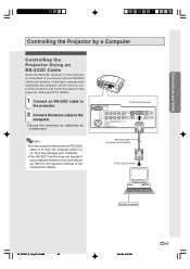
...RS-232C cable (null modem, cross type, commercially available), the computer can be used to the operation manual of the projector. Refer to control the projector and check the status of the computer for details. To RS-232C terminal RS-232C cable (commercially available) To RS-...232C terminal Desktop computer XV_Z12000_E_US_p15_26.p65 25 03.9.26, 6:37 PM -25 Connections and Setup Controlling the Projector by tightening the thumbscrews. Note • Do not connect or disconnect an RS-232C cable to the computer. • Secure the connectors...
...RS-232C cable (null modem, cross type, commercially available), the computer can be used to the operation manual of the projector. Refer to control the projector and check the status of the computer for details. To RS-232C terminal RS-232C cable (commercially available) To RS-...232C terminal Desktop computer XV_Z12000_E_US_p15_26.p65 25 03.9.26, 6:37 PM -25 Connections and Setup Controlling the Projector by tightening the thumbscrews. Note • Do not connect or disconnect an RS-232C cable to the computer. • Secure the connectors...


