
Operation Manual
Page 3
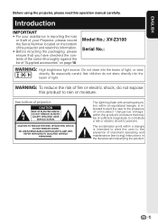
... of light. Do not stare into the beam of important operating and maintenance (servicing) instructions in reporting the loss or theft of your Projector, please record the Serial Number located on page 10. The lightning flash with arrowhead symbol, within an equilateral triangle, is intended to alert...Introduction IMPORTANT • For your assistance in the literature accompanying the product. 1 Be especially careful that children do not expose this operation manual carefully. CAUTION RISK OF ELECTRIC SHOCK. Model No.: XV-Z3100 Serial No.: WARNING: High brightness light source.
... of light. Do not stare into the beam of important operating and maintenance (servicing) instructions in reporting the loss or theft of your Projector, please record the Serial Number located on page 10. The lightning flash with arrowhead symbol, within an equilateral triangle, is intended to alert...Introduction IMPORTANT • For your assistance in the literature accompanying the product. 1 Be especially careful that children do not expose this operation manual carefully. CAUTION RISK OF ELECTRIC SHOCK. Model No.: XV-Z3100 Serial No.: WARNING: High brightness light source.
Operation Manual
Page 5
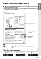
...Picture Mode Contrast Bright Color Tint Sharp Red Blue INPUT 1 Standard 0 0 0 0 0 0 0 Note • The "Fine Sync" menu is not available for setting up and operating the projector. SEL./ADJ. However, you can also be performed by using the projector. Using the Menu Screen ENTER ... • The selected icon is displayed. RETURN ENTER END 41 Useful Features Button used in this operation manual, the illustration and the screen display are slightly different, depending on the projector. 1 Press dMENU. • The "Picture" menu screen for the selected input mode is displayed. 2...
...Picture Mode Contrast Bright Color Tint Sharp Red Blue INPUT 1 Standard 0 0 0 0 0 0 0 Note • The "Fine Sync" menu is not available for setting up and operating the projector. SEL./ADJ. However, you can also be performed by using the projector. Using the Menu Screen ENTER ... • The selected icon is displayed. RETURN ENTER END 41 Useful Features Button used in this operation manual, the illustration and the screen display are slightly different, depending on the projector. 1 Press dMENU. • The "Picture" menu screen for the selected input mode is displayed. 2...
Operation Manual
Page 6
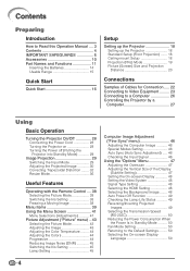
... Introduction How to Read this Operation Manual .... 3 Contents 4 IMPORTANT SAFEGUARDS 6 Accessories 10 Part Names and Functions 11 Inserting the Batteries 14 Usable Range 15 Quick Start Quick Start 16 Setup Setting up the Projector 18 Setting up the Projector 18 Standard Setup (Front Projection) ... 23 Connecting to a Computer 26 Controlling the Projector by a Computer 27 Using Basic Operation Turning the Projector On/Off 28 Connecting the Power Cord 28 Turning the Projector on 28 Turning the Power off (Putting the Projector into Standby Mode 29 Image Projection 29 Switching...
... Introduction How to Read this Operation Manual .... 3 Contents 4 IMPORTANT SAFEGUARDS 6 Accessories 10 Part Names and Functions 11 Inserting the Batteries 14 Usable Range 15 Quick Start Quick Start 16 Setup Setting up the Projector 18 Setting up the Projector 18 Standard Setup (Front Projection) ... 23 Connecting to a Computer 26 Controlling the Projector by a Computer 27 Using Basic Operation Turning the Projector On/Off 28 Connecting the Power Cord 28 Turning the Projector on 28 Turning the Power off (Putting the Projector into Standby Mode 29 Image Projection 29 Switching...
Operation Manual
Page 11
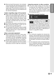
...is automatically controlled. This can result in internal temperature, as the cooling fan also stops. 9 Before moving the projector, make the connections. I Please read the operation manuals of the picture. Doing so may change during projection or cooling fan operation. I When storing the... projector, ensure you unplug the power cord from the AC outlet and turning off the projector, the cooling fan runs to decrease the...
...is automatically controlled. This can result in internal temperature, as the cooling fan also stops. 9 Before moving the projector, make the connections. I Please read the operation manuals of the picture. Doing so may change during projection or cooling fan operation. I When storing the... projector, ensure you unplug the power cord from the AC outlet and turning off the projector, the cooling fan runs to decrease the...

Operation Manual
Page 12
... pin RCA conversion adaptor QSOCZ0361CEZZ Power cord* (1) Video cable • Operation manual QCNWGA001WJZZ (2) (3) For Europe, except U.K. (6' (1.8 m)) QACCVA011WJPZ For U.K. Optional accessories I Lamp unit I DIN-D-sub RS-232C adaptor (5 57/64o (15 cm)) I 3 RCA to the wall outlet in your nearest Sharp Authorized Projector Dealer or Service Center. 10 and Singapore (6' (1.8 m)) QACCBA036WJPZ For Australia, New...
... pin RCA conversion adaptor QSOCZ0361CEZZ Power cord* (1) Video cable • Operation manual QCNWGA001WJZZ (2) (3) For Europe, except U.K. (6' (1.8 m)) QACCVA011WJPZ For U.K. Optional accessories I Lamp unit I DIN-D-sub RS-232C adaptor (5 57/64o (15 cm)) I 3 RCA to the wall outlet in your nearest Sharp Authorized Projector Dealer or Service Center. 10 and Singapore (6' (1.8 m)) QACCBA036WJPZ For Australia, New...

Operation Manual
Page 13
... adjusting the focus. Introduction Part Names and Functions Numbers in Z refer to attach or remove. 11 Projector Top View Power indicator 28, 54 28, 54 Lamp indicator STANDBY/ON 28 button For turning the .... RESIZE button 36 For switching the screen size. ENTER button For setting 41 items selected or adjusted on and putting the projector into standby mode. HEIGHT 30 ADJUST lever 54 Temperature warning indicator 29 INPUT buttons (P/R) For switching input mode 1, 2, 3,... both sides of the lens cap to the main pages in this operation manual where the topic is explained.
... adjusting the focus. Introduction Part Names and Functions Numbers in Z refer to attach or remove. 11 Projector Top View Power indicator 28, 54 28, 54 Lamp indicator STANDBY/ON 28 button For turning the .... RESIZE button 36 For switching the screen size. ENTER button For setting 41 items selected or adjusted on and putting the projector into standby mode. HEIGHT 30 ADJUST lever 54 Temperature warning indicator 29 INPUT buttons (P/R) For switching input mode 1, 2, 3,... both sides of the lens cap to the main pages in this operation manual where the topic is explained.

Operation Manual
Page 14
.... 6 RS-232C terminal Connecting the computer to the main pages in Z refer to control the projector. Part Names and Functions (Continued) Numbers in this operation manual where the topic is turned on , a control signal (DC 12V) outputs from this terminal. ... S-video output terminal (VCR, DVD player, etc.). 3 INPUT 4 terminal Connecting video equipment without S-video output terminal. TRIGGER terminal 7 When the projector is turned on . Rear adjustment 31 foot Terminals 15 Remote control sensor (rear) 13 Kensington Security Standard connector 65 4 1 23 7 Terminal Description...
.... 6 RS-232C terminal Connecting the computer to the main pages in Z refer to control the projector. Part Names and Functions (Continued) Numbers in this operation manual where the topic is turned on , a control signal (DC 12V) outputs from this terminal. ... S-video output terminal (VCR, DVD player, etc.). 3 INPUT 4 terminal Connecting video equipment without S-video output terminal. TRIGGER terminal 7 When the projector is turned on . Rear adjustment 31 foot Terminals 15 Remote control sensor (rear) 13 Kensington Security Standard connector 65 4 1 23 7 Terminal Description...

Operation Manual
Page 15
...SYNC button 46 For automatically adjusting images when connected to the respective input signal type. Using the Kensington Lock on the projector • This projector has a Kensington Security Standard connector for use with the system for instructions on how to use it to the respective input...2, 3, 4, 5 and 6 buttons For switching to secure the projector. 13 STANDBY button 29 For putting the projector into the standby mode. RGB/COMP. RETURN button 41 For returning to the main pages in this operation manual where the topic is explained. 28 ON button For turning the ...
...SYNC button 46 For automatically adjusting images when connected to the respective input signal type. Using the Kensington Lock on the projector • This projector has a Kensington Security Standard connector for use with the system for instructions on how to use it to the respective input...2, 3, 4, 5 and 6 buttons For switching to secure the projector. 13 STANDBY button 29 For putting the projector into the standby mode. RGB/COMP. RETURN button 41 For returning to the main pages in this operation manual where the topic is explained. 28 ON button For turning the ...

Operation Manual
Page 24
...Cables for a camera or a video game Compo- Equipment Audio-visual equipment Input Signal HDMI video Cable HDMI cable (commercially available) Terminal on the projector INPUT6 Component video Component cable (commercially available) Component video 3 RCA to 15-pin D-sub cable (optional accessory: AN-C3CP2) S-video cable .... • You may need other cables or connectors not listed below. nent video INPUT1, 2 Component video 3 RCA to the operation manual of connection and cables, refer to 15-pin D-sub INPUT5 Cables for a camera cable (optional or a video game accessory: AN-C3CP2...
...Cables for a camera or a video game Compo- Equipment Audio-visual equipment Input Signal HDMI video Cable HDMI cable (commercially available) Terminal on the projector INPUT6 Component video Component cable (commercially available) Component video 3 RCA to 15-pin D-sub cable (optional accessory: AN-C3CP2) S-video cable .... • You may need other cables or connectors not listed below. nent video INPUT1, 2 Component video 3 RCA to the operation manual of connection and cables, refer to 15-pin D-sub INPUT5 Cables for a camera cable (optional or a video game accessory: AN-C3CP2...
Operation Manual
Page 28
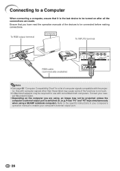
Connecting to a Computer When connecting a computer, ensure that you are using a SHARP notebook computer). To RGB output terminal Computer Supplied accessory To INPUT5 terminal RGB cable (commercially available) Note • See page 61 "Computer Compatibility ... output port is the last device to be turned on . (e.g. est Macintosh Dealer. • Depending on the computer you have read the operation manuals of the devices to be connected before making connections. Use with the projec- Contact your computer's external output port. 26 Ensure that it is switched...
Connecting to a Computer When connecting a computer, ensure that you are using a SHARP notebook computer). To RGB output terminal Computer Supplied accessory To INPUT5 terminal RGB cable (commercially available) Note • See page 61 "Computer Compatibility ... output port is the last device to be turned on . (e.g. est Macintosh Dealer. • Depending on the computer you have read the operation manuals of the devices to be connected before making connections. Use with the projec- Contact your computer's external output port. 26 Ensure that it is switched...

Operation Manual
Page 29
... (optional accessory: AN-A1RS) and an RS-232C serial control cable (cross type, commercially available), the computer can be used to control the projector and check the status of an RS-232C serial control cable. This may not operate if your computer terminal is not correctly set up. See... page 60 for connection of the projector. Refer to the operation manual of the computer for details. • See page 60 for detail. When connecting to a port other than the RS-232C terminal ...
... (optional accessory: AN-A1RS) and an RS-232C serial control cable (cross type, commercially available), the computer can be used to control the projector and check the status of an RS-232C serial control cable. This may not operate if your computer terminal is not correctly set up. See... page 60 for connection of the projector. Refer to the operation manual of the computer for details. • See page 60 for detail. When connecting to a port other than the RS-232C terminal ...

Operation Manual
Page 48
..." and press i ENTER. 3 Auto Sync (Auto Sync Adjustment) Selectable items On Off Description Auto Sync adjustment will occur when the projector is also performed by moving it up or down. Auto Sync adjustment is selected. • The adjustable area of irregularities such as ...0 0 0 0 1080I On 2 Special Modes Setting Ordinarily, the type of the computer connected to the projector. • When the optimum image cannot be achieved with Auto Sync adjustment, use manual adjustments. 4 Checking the Input Signal This function allows you to check the current input signal information. 46...
..." and press i ENTER. 3 Auto Sync (Auto Sync Adjustment) Selectable items On Off Description Auto Sync adjustment will occur when the projector is also performed by moving it up or down. Auto Sync adjustment is selected. • The adjustable area of irregularities such as ...0 0 0 0 1080I On 2 Special Modes Setting Ordinarily, the type of the computer connected to the projector. • When the optimum image cannot be achieved with Auto Sync adjustment, use manual adjustments. 4 Checking the Input Signal This function allows you to check the current input signal information. 46...

Operation Manual
Page 64
...projector is due to the external output. INPUT 6 (Component). 48 Picture is switched to cabinet shrinkage - Page 28 - 29 23-27 14 26 57, 58 52, 53 23-27 43 - • Image adjustments are using, an image may not be used. noise appears. • There is to the computer's operation manual... to the external connected devices is off. • The selected input mode is wrong. • Cables incorrectly connected to the projector. • "Bright" is blurred; If condensation should form, remove the power cord from caused by room temperature changes. Maintenance indicator...
...projector is due to the external output. INPUT 6 (Component). 48 Picture is switched to cabinet shrinkage - Page 28 - 29 23-27 14 26 57, 58 52, 53 23-27 43 - • Image adjustments are using, an image may not be used. noise appears. • There is to the computer's operation manual... to the external connected devices is off. • The selected input mode is wrong. • Cables incorrectly connected to the projector. • "Bright" is blurred; If condensation should form, remove the power cord from caused by room temperature changes. Maintenance indicator...
Operation Manual
Page 66
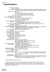
...manual *1 When STANDBY Mode is set to "Eco" As a part of policy of production units. The performance specification figures indicated are nominal values of continuous improvement, SHARP... Power cord for product improvement without prior notice. Specifications Product type Projector Model XV-Z3100 Video system NTSC3.58/NTSC4.43/PAL/PAL-M/PAL-N/PAL-60/SECAM.../DTV480I/DTV480P/ DTV540P/DTV576I/DTV576P/DTV720P/DTV1035I/DTV1080I/DTV1080I-50 Display method DLP® chip Panel size: 0.62" Drive method: Digital Light Processing (DLP...
...manual *1 When STANDBY Mode is set to "Eco" As a part of policy of production units. The performance specification figures indicated are nominal values of continuous improvement, SHARP... Power cord for product improvement without prior notice. Specifications Product type Projector Model XV-Z3100 Video system NTSC3.58/NTSC4.43/PAL/PAL-M/PAL-N/PAL-60/SECAM.../DTV480I/DTV480P/ DTV540P/DTV576I/DTV576P/DTV720P/DTV1035I/DTV1080I/DTV1080I-50 Display method DLP® chip Panel size: 0.62" Drive method: Digital Light Processing (DLP...


