
Operation Manual
Page 3
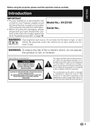
... USER SERVICE SCREW. CAUTION: TO REDUCE THE RISK OF ELECTRIC SHOCK, DO NOT REMOVE COVER. Do not stare into the beam of projector. The exclamation point within a triangle is intended to alert the user to the presence of uninsulated "dangerous voltage" within an equilateral triangle, is intended to alert the user to persons. Model No.: XV-Z3100 Serial No.: WARNING: High brightness light source. The lightning flash...
... USER SERVICE SCREW. CAUTION: TO REDUCE THE RISK OF ELECTRIC SHOCK, DO NOT REMOVE COVER. Do not stare into the beam of projector. The exclamation point within a triangle is intended to alert the user to the presence of uninsulated "dangerous voltage" within an equilateral triangle, is intended to alert the user to persons. Model No.: XV-Z3100 Serial No.: WARNING: High brightness light source. The lightning flash...

Operation Manual
Page 4
... acceptable tolerances that the equipment must conform to run for about 90 seconds after the projector enters standby mode. During normal operation, when putting the projector into standby mode always use the STANDBY/ON button on the projector or the STANDBY button on the remote control. As with any high technology electronic equipment such as large screen TVs, video systems and video cameras, there are located in this projector continues to .
... acceptable tolerances that the equipment must conform to run for about 90 seconds after the projector enters standby mode. During normal operation, when putting the projector into standby mode always use the STANDBY/ON button on the projector or the STANDBY button on the remote control. As with any high technology electronic equipment such as large screen TVs, video systems and video cameras, there are located in this projector continues to .
Operation Manual
Page 5
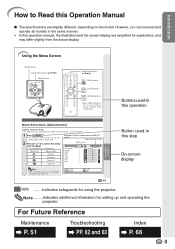
Menu icon Menu screen Picture Fine Sync Options1 Options2 Example: "Picture" screen menu for INPUT 1 mode Selected input mode Menu icons Picture Picture Mode Contrast Bright Color Tint Sharp Red Blue INPUT 1 Standard 0 0 0 0 0 0 0 Note • The "Fine Sync" menu is displayed. However, you can also be performed by using the projector. SEL./ADJ. Note .........Indicates additional information for INPUT 3 or INPUT 4. Introduction How to Read this Operation Manual I The specifications are simplified for explanation, and may differ slightly from the actual display. For Future...
Menu icon Menu screen Picture Fine Sync Options1 Options2 Example: "Picture" screen menu for INPUT 1 mode Selected input mode Menu icons Picture Picture Mode Contrast Bright Color Tint Sharp Red Blue INPUT 1 Standard 0 0 0 0 0 0 0 Note • The "Fine Sync" menu is displayed. However, you can also be performed by using the projector. SEL./ADJ. Note .........Indicates additional information for INPUT 3 or INPUT 4. Introduction How to Read this Operation Manual I The specifications are simplified for explanation, and may differ slightly from the actual display. For Future...
Operation Manual
Page 6
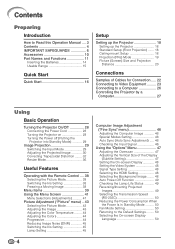
... the Projector 18 Standard Setup (Front Projection) ....... 18 Ceiling-mount Setup 18 Projection (PRJ) Mode 19 Picture (Screen) Size and Projection Distance 20 Connections Samples of Cables for Connection ..... 22 Connecting to Video Equipment ......... 23 Connecting to a Computer 26 Controlling the Projector by a Computer 27 Using Basic Operation Turning the Projector On/Off 28 Connecting the Power Cord 28 Turning the Projector on 28 Turning the Power off (Putting the Projector into Standby Mode 29 Image Projection 29 Switching the Input Mode 29 Adjusting the Projected Image 30...
... the Projector 18 Standard Setup (Front Projection) ....... 18 Ceiling-mount Setup 18 Projection (PRJ) Mode 19 Picture (Screen) Size and Projection Distance 20 Connections Samples of Cables for Connection ..... 22 Connecting to Video Equipment ......... 23 Connecting to a Computer 26 Controlling the Projector by a Computer 27 Using Basic Operation Turning the Projector On/Off 28 Connecting the Power Cord 28 Turning the Projector on 28 Turning the Power off (Putting the Projector into Standby Mode 29 Image Projection 29 Switching the Input Mode 29 Adjusting the Projected Image 30...
Operation Manual
Page 10
... Sharp Authorized Projector Dealer or Service Center for replacement. I If the cooling fan becomes obstructed, a protection circuit will cause eye strain. Do not block the exhaust and intake vents. This does not indicate a malfunction. (See pages 54 and 55.) Remove the projector power cord from -4°F to 140°F (-20°C to the normal operating condition. When the projector is regularly cleaned, use the projector...
... Sharp Authorized Projector Dealer or Service Center for replacement. I If the cooling fan becomes obstructed, a protection circuit will cause eye strain. Do not block the exhaust and intake vents. This does not indicate a malfunction. (See pages 54 and 55.) Remove the projector power cord from -4°F to 140°F (-20°C to the normal operating condition. When the projector is regularly cleaned, use the projector...
Operation Manual
Page 11
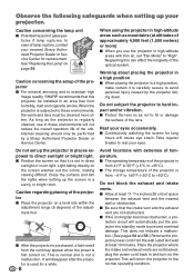
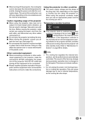
... may change during projection or cooling fan operation. The sound of the projector and the equipment to heat sources. Introduction I When using the projector in. Caution regarding usage of the plastic cover. I Do not expose the projector to direct sunlight or place next to be connected. I When storing the projector, ensure you unplug the power cord from the AC outlet and turning off , the temperature warn- When using the projector...
... may change during projection or cooling fan operation. The sound of the projector and the equipment to heat sources. Introduction I When using the projector in. Caution regarding usage of the plastic cover. I Do not expose the projector to direct sunlight or place next to be connected. I When storing the projector, ensure you unplug the power cord from the AC outlet and turning off , the temperature warn- When using the projector...

Operation Manual
Page 13
... of the lens cap to the main pages in this operation manual where the topic is explained. ENTER button For setting 41 items selected or adjusted on and putting the projector into standby mode. RESIZE button 36 For switching the screen size. Introduction Part Names and Functions Numbers in Z refer to attach or remove. 11 Projector Top View Power indicator 28, 54 28, 54 Lamp indicator STANDBY/ON 28 button For turning the power on the...
... of the lens cap to the main pages in this operation manual where the topic is explained. ENTER button For setting 41 items selected or adjusted on and putting the projector into standby mode. RESIZE button 36 For switching the screen size. Introduction Part Names and Functions Numbers in Z refer to attach or remove. 11 Projector Top View Power indicator 28, 54 28, 54 Lamp indicator STANDBY/ON 28 button For turning the power on the...

Operation Manual
Page 15
... images. 29 INPUT 1, 2, 3, 4, 5 and 6 buttons For switching to the respective input modes. 41 MENU button For displaying adjustment and setting screens. 41 Adjustment buttons (P/R/O/Q) • For selecting menu items. • For adjusting the Keystone Correction when in this operation manual where the topic is explained. 28 ON button For turning the power on how to use with a Kensington MicroSaver Security System. Using the Kensington Lock on the projector • This projector has a Kensington Security Standard connector for instructions...
... images. 29 INPUT 1, 2, 3, 4, 5 and 6 buttons For switching to the respective input modes. 41 MENU button For displaying adjustment and setting screens. 41 Adjustment buttons (P/R/O/Q) • For selecting menu items. • For adjusting the Keystone Correction when in this operation manual where the topic is explained. 28 ON button For turning the power on how to use with a Kensington MicroSaver Security System. Using the Kensington Lock on the projector • This projector has a Kensington Security Standard connector for instructions...

Operation Manual
Page 19
... turning the zoom ring. Adjust the projector angle using the INPUT buttons on the projector or the INPUT 4 button on the remote control. Press P/R/O/Q on the remote control also allows you confirm the lower left position, the screen adjustments will end. 8. Follow steps 2 and 3 to set and setup will be set the upper-left positions of the projected image. 3. Press c KEYSTONE on and start playback 5. On the On the remote projector control On-screen Display • Unplug the power cord...
... turning the zoom ring. Adjust the projector angle using the INPUT buttons on the projector or the INPUT 4 button on the remote control. Press P/R/O/Q on the remote control also allows you confirm the lower left position, the screen adjustments will end. 8. Follow steps 2 and 3 to set and setup will be set the upper-left positions of the projected image. 3. Press c KEYSTONE on and start playback 5. On the On the remote projector control On-screen Display • Unplug the power cord...
Operation Manual
Page 30
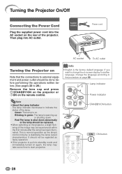
... illuminated. STANDBY/ON button ON button 28 Info • English is warming up or shutting down abnormally or the lamp should be replaced. • When switching on the projector, a slight flickering of the image may take some time to indicate the status of the projector. Blinking in green: The lamp is the factory default language. Then plug into AC outlet. Lamp indicator Power indicator Note • About the Lamp Indicator The lamp indicator illuminates to start projection. Supplied accessory Power cord AC...
... illuminated. STANDBY/ON button ON button 28 Info • English is warming up or shutting down abnormally or the lamp should be replaced. • When switching on the projector, a slight flickering of the image may take some time to indicate the status of the projector. Blinking in green: The lamp is the factory default language. Then plug into AC outlet. Lamp indicator Power indicator Note • About the Lamp Indicator The lamp indicator illuminates to start projection. Supplied accessory Power cord AC...

Operation Manual
Page 42
... 1 Overscan H Overscan V Subtitle OSD Display Video System Signal Type HDMI Setting Background Auto Power Off INPUT 1 0 0 0 On Auto Auto Standard Blue On Lamp Timer(Life) SEL./ADJ. "Options2" menu Options 2 PRJ Mode RS-232C STANDBY Mode Fan Mode All Reset Language INPUT 1 Front 9600 bps Eco Normal English SEL./ADJ. Menu Items (Continued) "Fine Sync" menu Fine Sync Clock Phase H-Pos V-Pos Reset Special Modes Auto Sync INPUT 5 0 0 0 0 1080I On Cur. RETURN 40 ENTER END Main menu Fine Sync Page 46 Clock -150...
... 1 Overscan H Overscan V Subtitle OSD Display Video System Signal Type HDMI Setting Background Auto Power Off INPUT 1 0 0 0 On Auto Auto Standard Blue On Lamp Timer(Life) SEL./ADJ. "Options2" menu Options 2 PRJ Mode RS-232C STANDBY Mode Fan Mode All Reset Language INPUT 1 Front 9600 bps Eco Normal English SEL./ADJ. Menu Items (Continued) "Fine Sync" menu Fine Sync Clock Phase H-Pos V-Pos Reset Special Modes Auto Sync INPUT 5 0 0 0 0 1080I On Cur. RETURN 40 ENTER END Main menu Fine Sync Page 46 Clock -150...
Operation Manual
Page 45
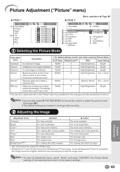
... select the picture mode. (See page 38.) • The default settings are retained in RGB mode. *2 BrilliantColor™ uses Texas Instruments' BrilliantColor™ technology. For more pronounced and vivid. For making the effect weaker. For stronger red. Blue BrilliantColor™*2 For weaker blue. Picture Adjustment ("Picture" menu) Q PAGE 1 Picture Picture Mode Contrast Bright Color Tint Sharp Red Blue INPUT 1 Standard 0 0 0 0 0 0 0 Q PAGE 2 Picture Picture Mode CLR Temp BrilliantColor™ C. M. Progressive DNR IRIS Lamp Setting Reset Menu operation n Page 41...
... select the picture mode. (See page 38.) • The default settings are retained in RGB mode. *2 BrilliantColor™ uses Texas Instruments' BrilliantColor™ technology. For more pronounced and vivid. For making the effect weaker. For stronger red. Blue BrilliantColor™*2 For weaker blue. Picture Adjustment ("Picture" menu) Q PAGE 1 Picture Picture Mode Contrast Bright Color Tint Sharp Red Blue INPUT 1 Standard 0 0 0 0 0 0 0 Q PAGE 2 Picture Picture Mode CLR Temp BrilliantColor™ C. M. Progressive DNR IRIS Lamp Setting Reset Menu operation n Page 41...

Operation Manual
Page 50
... option that case, switch the video signal. The video input system mode is selected. 7 Selecting the Background Image Selectable items Blue None Description Blue screen - (Black screen) 48 If this should be selected.) Note • The HDMI Setting can be set in PAL video equipment. INPUT/FREEZE/AUTO SYNC/RESIZE/ PICTURE MODE/IRIS are received. RGB Component Set when RGB signals are displayed. Using the "Options" Menu (Continued) Menu operation n Page 41 3 Setting the On-screen Display Selectable items On...
... option that case, switch the video signal. The video input system mode is selected. 7 Selecting the Background Image Selectable items Blue None Description Blue screen - (Black screen) 48 If this should be selected.) Note • The HDMI Setting can be set in PAL video equipment. INPUT/FREEZE/AUTO SYNC/RESIZE/ PICTURE MODE/IRIS are received. RGB Component Set when RGB signals are displayed. Using the "Options" Menu (Continued) Menu operation n Page 41 3 Setting the On-screen Display Selectable items On...

Operation Manual
Page 51
... no input signal is detected for details of the screen or with a mirror) Reversed and inverted image (Projected with Lamp Setting set to "On", 5 minutes before the projector enters standby mode, the message "Enter STANDBY mode in X min." Options 2 1 PRJ Mode 2 RS-232C 3 STANDBY Mode 4 Fan Mode 5 All Reset 6 Language Menu operation n Page 41 INPUT 1 Front 9600 bps Eco Normal English Settings on the usage condition. will be changed when the remaining lamp life becomes 5%. • The lamp life may...
... no input signal is detected for details of the screen or with a mirror) Reversed and inverted image (Projected with Lamp Setting set to "On", 5 minutes before the projector enters standby mode, the message "Enter STANDBY mode in X min." Options 2 1 PRJ Mode 2 RS-232C 3 STANDBY Mode 4 Fan Mode 5 All Reset 6 Language Menu operation n Page 41 INPUT 1 Front 9600 bps Eco Normal English Settings on the usage condition. will be changed when the remaining lamp life becomes 5%. • The lamp life may...
Operation Manual
Page 57
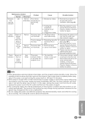
... using the projector, and the power supply recovers immediately after the projector has entered standby mode and while the cooling fan is warming up or turning off for advice. Time to your nearest Sharp Authorized Projector Dealer or Service Center for repair. • Please exercise care when replacing the lamp. • Securely install the cover. • If the power indicator blinks in red even when the dust filter holders and lamp unit cover are securely installed...
... using the projector, and the power supply recovers immediately after the projector has entered standby mode and while the cooling fan is warming up or turning off for advice. Time to your nearest Sharp Authorized Projector Dealer or Service Center for repair. • Please exercise care when replacing the lamp. • Securely install the cover. • If the power indicator blinks in red even when the dust filter holders and lamp unit cover are securely installed...
Operation Manual
Page 60
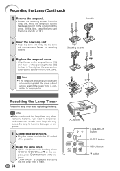
... tighten the user service screw (3) to reset the lamp timer only when replacing the lamp. Info • If the lamp unit and lamp unit cover are not correctly installed, the power will not turn on the lamp unit cover (1) and place it while pressing the tab (2) to use the same lamp, this time, keep the lamp unit horizontal and do not tilt it in the direction of the projector. 2 Reset the lamp timer. • While...
... tighten the user service screw (3) to reset the lamp timer only when replacing the lamp. Info • If the lamp unit and lamp unit cover are not correctly installed, the power will not turn on the lamp unit cover (1) and place it while pressing the tab (2) to use the same lamp, this time, keep the lamp unit horizontal and do not tilt it in the direction of the projector. 2 Reset the lamp timer. • While...

Operation Manual
Page 64
... not been set when connecting notebook computer. • The lamp unit cover is not installed correctly. • The dust filter holders are not installed correctly. • Cables incorrectly connected to the projector. • "Bright" is suddenly heated, condensation may form on the computer. - or performance. Troubleshooting Problem Check Picure does not appear or projector does not start. No picture appears (or picture is dark). • Projector power cord is not...
... not been set when connecting notebook computer. • The lamp unit cover is not installed correctly. • The dust filter holders are not installed correctly. • Cables incorrectly connected to the projector. • "Bright" is suddenly heated, condensation may form on the computer. - or performance. Troubleshooting Problem Check Picure does not appear or projector does not start. No picture appears (or picture is dark). • Projector power cord is not...

Operation Manual
Page 65
... batteries may be affected by incorrect operation or interference. The lamp does not light • The lamp indicator is equipped with a microprocessor. time to turn on . Make sure the batteries are incorrectly set. Appendix 63 Problem Check Page Picture is dark. up even after more than 5 minutes. The image sometimes flickers. • Cables incorrectly connected to the projector or the connected equipment works improperly. • If this should...
... batteries may be affected by incorrect operation or interference. The lamp does not light • The lamp indicator is equipped with a microprocessor. time to turn on . Make sure the batteries are incorrectly set. Appendix 63 Problem Check Page Picture is dark. up even after more than 5 minutes. The image sometimes flickers. • Cables incorrectly connected to the projector or the connected equipment works improperly. • If this should...
Operation Manual
Page 66
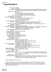
...) VERTICAL SYNC. Specifications Product type Projector Model XV-Z3100 Video system NTSC3.58/NTSC4.43/PAL/PAL-M/PAL-N/PAL-60/SECAM/DTV480I/DTV480P/ DTV540P/DTV576I/DTV576P/DTV720P/DTV1035I/DTV1080I/DTV1080I-50 Display method DLP® chip Panel size: 0.62" Drive method: Digital Light Processing (DLP®) No. There may be some deviations from these values in individual units. 64 and Singapore, Power cord for Australia, New Zealand and...
...) VERTICAL SYNC. Specifications Product type Projector Model XV-Z3100 Video system NTSC3.58/NTSC4.43/PAL/PAL-M/PAL-N/PAL-60/SECAM/DTV480I/DTV480P/ DTV540P/DTV576I/DTV576P/DTV720P/DTV1035I/DTV1080I/DTV1080I-50 Display method DLP® chip Panel size: 0.62" Drive method: Digital Light Processing (DLP®) No. There may be some deviations from these values in individual units. 64 and Singapore, Power cord for Australia, New Zealand and...

Operation Manual
Page 68
... 36 Auto Power Off 49 Auto Sync (Auto Sync adjustment 46 AUTO SYNC button 46 Background 48 Backlight button 13 Blue 43 Bright 43 BrilliantColor 43 Checking the Input Signal 46 CINEMA ZOOM 36, 37 Clock 46 CLR Temp (Color Temperature 44 C.M.S 44 Color 43 Contrast 43 DOT BY DOT 37 DNR 45 Dust filters 52 ENTER button 41 Exhaust vent 12, 51 Fan Mode 50 Fine Sync 46 Focus ring 30 FREEZE button 38 GEOMETRIC ADJUSTMENT 34 H & V KEYSTONE 35 HDMI Setting 48...
... 36 Auto Power Off 49 Auto Sync (Auto Sync adjustment 46 AUTO SYNC button 46 Background 48 Backlight button 13 Blue 43 Bright 43 BrilliantColor 43 Checking the Input Signal 46 CINEMA ZOOM 36, 37 Clock 46 CLR Temp (Color Temperature 44 C.M.S 44 Color 43 Contrast 43 DOT BY DOT 37 DNR 45 Dust filters 52 ENTER button 41 Exhaust vent 12, 51 Fan Mode 50 Fine Sync 46 Focus ring 30 FREEZE button 38 GEOMETRIC ADJUSTMENT 34 H & V KEYSTONE 35 HDMI Setting 48...


