
Operation Manual
Page 2
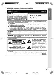
..., do not stare directly into the beam of actual set. CAUTION RISK OF ELECTRIC SHOCK. DO NOT REMOVE SCREWS EXCEPT SPECIFIED USER SERVICE SCREWS. CAUTION: TO REDUCE THE RISK OF ELECTRIC SHOCK, DO NOT REMOVE COVER. See bottom of light, or view directly. NO USER-SERVICEABLE PARTS EXCEPT LAMP UNIT. The lightning flash with the projector. 1. U.S.A. Model No.: XV-Z10000 Serial No.: There are two important reasons for prompt warranty...
..., do not stare directly into the beam of actual set. CAUTION RISK OF ELECTRIC SHOCK. DO NOT REMOVE SCREWS EXCEPT SPECIFIED USER SERVICE SCREWS. CAUTION: TO REDUCE THE RISK OF ELECTRIC SHOCK, DO NOT REMOVE COVER. See bottom of light, or view directly. NO USER-SERVICEABLE PARTS EXCEPT LAMP UNIT. The lightning flash with the projector. 1. U.S.A. Model No.: XV-Z10000 Serial No.: There are two important reasons for prompt warranty...

Operation Manual
Page 3
... rules. These limits are located in a residential installation. Ensure the cooling fan has stopped before disconnecting the power cord. For disposal or recycling information, please contact your local authorities or, if you may be determined by turning the equipment off always use the power (OFF) button on the projector or on page 76. Caution Concerning the Lamp Replacement See "Replacing the Lamp" on the remote control.
... rules. These limits are located in a residential installation. Ensure the cooling fan has stopped before disconnecting the power cord. For disposal or recycling information, please contact your local authorities or, if you may be determined by turning the equipment off always use the power (OFF) button on the projector or on page 76. Caution Concerning the Lamp Replacement See "Replacing the Lamp" on the remote control.
Operation Manual
Page 4
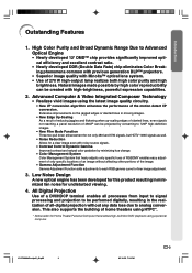
.... • Noise Reduction Allows for finer image adjustment. 3. High Color Purity and Broad Dynamic Range Due to analog conversion. Low Noise Design A new optical engine has been developed for undisturbed viewing. 4. All Digital Projection Use of a DVI/HDCP terminal enables all processes from input to signal processing and projection to be performed digitally, resulting in minimized fan noise for this product resulting in the...
.... • Noise Reduction Allows for finer image adjustment. 3. High Color Purity and Broad Dynamic Range Due to analog conversion. Low Noise Design A new optical engine has been developed for undisturbed viewing. 4. All Digital Projection Use of a DVI/HDCP terminal enables all processes from input to signal processing and projection to be performed digitally, resulting in minimized fan noise for this product resulting in the...
Operation Manual
Page 5
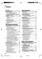
... Color 51 Resetting User-Defined Color Settings 52 Overview of All Color Settings 52 Adjusting Computer Images 53 When Auto Sync is OFF 53 Saving Adjustment Settings 53 Selecting Adjustment Settings 54 Special Mode Settings 54 Checking the Input Signal 55 Auto Sync Adjustment 55 Auto Sync Display Function 56 Easy to the Projector .... 24 Using the Adjustment Feet 25 Adjusting the Lens 26 Using the Lens Shift 27 Selecting the HIGH CONTRAST/ HIGH BRIGHTNESS MODE 27 Setting up your projector 8 How to Access the PDF Operation Manuals of SharpVision Manager 9 Part...
... Color 51 Resetting User-Defined Color Settings 52 Overview of All Color Settings 52 Adjusting Computer Images 53 When Auto Sync is OFF 53 Saving Adjustment Settings 53 Selecting Adjustment Settings 54 Special Mode Settings 54 Checking the Input Signal 55 Auto Sync Adjustment 55 Auto Sync Display Function 56 Easy to the Projector .... 24 Using the Adjustment Feet 25 Adjusting the Lens 26 Using the Lens Shift 27 Selecting the HIGH CONTRAST/ HIGH BRIGHTNESS MODE 27 Setting up your projector 8 How to Access the PDF Operation Manuals of SharpVision Manager 9 Part...
Operation Manual
Page 6
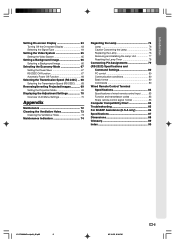
... Maintenance Indicators 74 Regarding the Lamp 76 Lamp 76 Caution Concerning the Lamp 76 Replacing the Lamp 76 Removing and Installing the Lamp Unit 77 Resetting the Lamp Timer 78 Connecting Pin Assignments 79 (RS-232C) Specifications and Command Settings 80 PC control 80 Communication conditions 80 Basic format 80 Commands 80 Wired Remote Control Terminal Specifications 83 Specifications of wired remote control input 83 Function and transmisson codes 83 Sharp remote control signal format 83 Computer Compatibility Chart 84 Troubleshooting...
... Maintenance Indicators 74 Regarding the Lamp 76 Lamp 76 Caution Concerning the Lamp 76 Replacing the Lamp 76 Removing and Installing the Lamp Unit 77 Resetting the Lamp Timer 78 Connecting Pin Assignments 79 (RS-232C) Specifications and Command Settings 80 PC control 80 Communication conditions 80 Basic format 80 Commands 80 Wired Remote Control Terminal Specifications 83 Specifications of wired remote control input 83 Function and transmisson codes 83 Sharp remote control signal format 83 Computer Compatibility Chart 84 Troubleshooting...
Operation Manual
Page 9
... and dim the lights when setting up the screen in and turn on how to make the connections AFTER turning off , the temperature warning indicator on page 74 for long hours continuously will blink in direct sunlight or room light. I Position the screen so that it to +35°C). Rest your eyes occasionally. Avoid locations with the lens. This does not indicate a malfunction. Remove the projector power cord from 41...
... and dim the lights when setting up the screen in and turn on how to make the connections AFTER turning off , the temperature warning indicator on page 74 for long hours continuously will blink in direct sunlight or room light. I Position the screen so that it to +35°C). Rest your eyes occasionally. Avoid locations with the lens. This does not indicate a malfunction. Remove the projector power cord from 41...

Operation Manual
Page 11
... lens. -10 XV-Z10000#Print#p06_14.p65 10 32 Power (ON/OFF) buttons For turning the power on the menu. Replace the lamp when the indicator illuminates red. 32 Power indicator Illuminates red, when the projector is explained. UNDO button 37 For undoing an operation or returning to the main pages in this operation manual where the topic is in standby. Part Names Numbers in refer to the default settings. 32 MENU button For displaying adjustment and setting screens. 58 RESIZE button...
... lens. -10 XV-Z10000#Print#p06_14.p65 10 32 Power (ON/OFF) buttons For turning the power on the menu. Replace the lamp when the indicator illuminates red. 32 Power indicator Illuminates red, when the projector is explained. UNDO button 37 For undoing an operation or returning to the main pages in this operation manual where the topic is in standby. Part Names Numbers in refer to the default settings. 32 MENU button For displaying adjustment and setting screens. 58 RESIZE button...

Operation Manual
Page 13
...button For displaying adjustment and setting screens. 32 Adjustment buttons For selecting menu items. 32 INPUT buttons For switching to the respective input modes. 58 RESIZE button For switching the screen size (NORMAL, STRETCH, etc.) 47 PICTURE SETTING button For selecting the picture memory setting. AUTO SYNC button 55 For automatically adjusting images when connected to the respective input signal type. 32 Power (ON/OFF) buttons For turning the power on the menu. button 18 For switching to a computer. Part Names Remote Control (Front View) KEYSTONE button 36 For adjusting Keystone...
...button For displaying adjustment and setting screens. 32 Adjustment buttons For selecting menu items. 32 INPUT buttons For switching to the respective input modes. 58 RESIZE button For switching the screen size (NORMAL, STRETCH, etc.) 47 PICTURE SETTING button For selecting the picture memory setting. AUTO SYNC button 55 For automatically adjusting images when connected to the respective input signal type. 32 Power (ON/OFF) buttons For turning the power on the menu. button 18 For switching to a computer. Part Names Remote Control (Front View) KEYSTONE button 36 For adjusting Keystone...

Operation Manual
Page 30
Setup Screen Size and Projection Distance x yz Connections and Setup When using a wide screen (16:9) In case of displaying the 16:9 picture on the whole of the 16:9 screen. 16 9 : Picture area Screen size (16:9) Diag. (x) 300" 250" 200" 150" 133" 106" 100" 92" 84"...Screen size (diag.) (inches) y : Projection distance (feet) z : Distance from the lens center to the lower edge of the screen (feet) Note • There is an error of ±3% in the formula above . • Values with a minus (-) sign indicate the distance of the lens center below the bottom of the screen. -29 XV-Z10000...
Setup Screen Size and Projection Distance x yz Connections and Setup When using a wide screen (16:9) In case of displaying the 16:9 picture on the whole of the 16:9 screen. 16 9 : Picture area Screen size (16:9) Diag. (x) 300" 250" 200" 150" 133" 106" 100" 92" 84"...Screen size (diag.) (inches) y : Projection distance (feet) z : Distance from the lens center to the lower edge of the screen (feet) Note • There is an error of ±3% in the formula above . • Values with a minus (-) sign indicate the distance of the lens center below the bottom of the screen. -29 XV-Z10000...

Operation Manual
Page 33
... turned off and immediately switched on again, the lamp replacement indicator may take time to start operation. Red: The lamp should be replaced. • If the power is ready to illuminate. • When controlling the projector using RS-232C commands from a computer, wait for at the factory is English. Power (OFF) button ENTER button Power indicator MENU button INPUT button Power (OFF) button Power (ON) button Power (ON) button MENU button ', ", \, | buttons INPUT buttons -32 XV-Z10000#Print#p31_39.p65 32 02.10.25, 7:29 PM Blue blinking: The lamp is ready. Blue...
... turned off and immediately switched on again, the lamp replacement indicator may take time to start operation. Red: The lamp should be replaced. • If the power is ready to illuminate. • When controlling the projector using RS-232C commands from a computer, wait for at the factory is English. Power (OFF) button ENTER button Power indicator MENU button INPUT button Power (OFF) button Power (ON) button Power (ON) button MENU button ', ", \, | buttons INPUT buttons -32 XV-Z10000#Print#p31_39.p65 32 02.10.25, 7:29 PM Blue blinking: The lamp is ready. Blue...

Operation Manual
Page 39
... +30 Reset (This Color) Reset (All Colors) View Settings Standard Custom 1 Custom 3 [R] Red [Y] Yellow [G] Green [C] Cyan [B] Blue [M] Magenta Main menu Fine Sync Page 53 Options Page 62 Language Page 34 Sub menu Clock -150 +150 Phase -60 +60 H-Pos -150 +150 V-Pos -60 +60 Reset Save Setting Select Setting Special Modes Signal Info Auto Sync Auto Sync Disp [ON/OFF] Digital Shift -XX +XX Subtitle -XX +XX Reset DNR Lamp Timer OSD Display * Signal Type Background Economy Mode RS...
... +30 Reset (This Color) Reset (All Colors) View Settings Standard Custom 1 Custom 3 [R] Red [Y] Yellow [G] Green [C] Cyan [B] Blue [M] Magenta Main menu Fine Sync Page 53 Options Page 62 Language Page 34 Sub menu Clock -150 +150 Phase -60 +60 H-Pos -150 +150 V-Pos -60 +60 Reset Save Setting Select Setting Special Modes Signal Info Auto Sync Auto Sync Disp [ON/OFF] Digital Shift -XX +XX Subtitle -XX +XX Reset DNR Lamp Timer OSD Display * Signal Type Background Economy Mode RS...

Operation Manual
Page 45
... "Reset" and press . -44 XV-Z10000#Print#p40_56.p65 44 02.10.25, 7:30 PM Note • Picture adjustment settings differ depending on the type of an image For less color intensity For more sharpness Increases color temperature for details. Adjusting the Picture You can be stored separately in each input mode. • Some parameters may not be able to be adjusted depending on the menu screen. ➝...
... "Reset" and press . -44 XV-Z10000#Print#p40_56.p65 44 02.10.25, 7:30 PM Note • Picture adjustment settings differ depending on the type of an image For less color intensity For more sharpness Increases color temperature for details. Adjusting the Picture You can be stored separately in each input mode. • Some parameters may not be able to be adjusted depending on the menu screen. ➝...
Operation Manual
Page 75
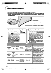
...warning indicator or the lamp replacement indicator will illuminate red, and the power will turn off. Power indicator Lamp replacement indicator Temperature warning indicator About the temperature warning indicator If the temperature inside the projector. jector increases, due to red, the lamp will be shut off. When the cumulative hours of use reach 2,000, " " will change to blockage of the picture. Power Blue on/ indicator Red on Red blinks The power indicator blinks in red. perature warning indicator will blink, the cooling fan will run for advice. -74 XV-Z10000...
...warning indicator or the lamp replacement indicator will illuminate red, and the power will turn off. Power indicator Lamp replacement indicator Temperature warning indicator About the temperature warning indicator If the temperature inside the projector. jector increases, due to red, the lamp will be shut off. When the cumulative hours of use reach 2,000, " " will change to blockage of the picture. Power Blue on/ indicator Red on Red blinks The power indicator blinks in red. perature warning indicator will blink, the cooling fan will run for advice. -74 XV-Z10000...
Operation Manual
Page 77
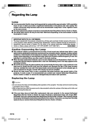
... -screen display icon are illuminated or flash, it is recommended you contact your nearest Authorized SharpVision Service Center or Dealer. I If the new lamp does not light after operation of the projector. In such a case, it is recommended that the lamp be replaced with a new one hour after the power cord is disconnected to allow the surface of the lamp unit to note that failure can be checked...
... -screen display icon are illuminated or flash, it is recommended you contact your nearest Authorized SharpVision Service Center or Dealer. I If the new lamp does not light after operation of the projector. In such a case, it is recommended that the lamp be replaced with a new one hour after the power cord is disconnected to allow the surface of the lamp unit to note that failure can be checked...
Operation Manual
Page 79
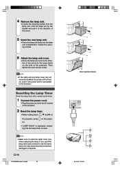
... the projector. Then tighten the user service screw. on , even if the power cord is reset. If you reset the lamp timer and continue to use the same lamp, this may cause the lamp to reset the lamp timer only when replacing the lamp. Info • Make sure to become damaged or explode. -78 XV-Z10000#Print#p71_84.p65 78 2 1 User service screws 02.10.25, 7:34 PM Resetting the Lamp Timer Reset the lamp timer after replacing the lamp. 1 Connect the power cord...
... the projector. Then tighten the user service screw. on , even if the power cord is reset. If you reset the lamp timer and continue to use the same lamp, this may cause the lamp to reset the lamp timer only when replacing the lamp. Info • Make sure to become damaged or explode. -78 XV-Z10000#Print#p71_84.p65 78 2 1 User service screws 02.10.25, 7:34 PM Resetting the Lamp Timer Reset the lamp timer after replacing the lamp. 1 Connect the power cord...

Operation Manual
Page 81
... for connection.) Communication conditions Set the serial port settings of the computer to match that of the projector, the projector's operating status cannot be read by transmitting the display commands for each command only after the response code for the previous command from the projector is verified. • In the case of transmitting commands during standby, it takes a maximum of INPUT 1 image adjustment is turned on during standby with the on-screen display. Signal format...
... for connection.) Communication conditions Set the serial port settings of the computer to match that of the projector, the projector's operating status cannot be read by transmitting the display commands for each command only after the response code for the previous command from the projector is verified. • In the case of transmitting commands during standby, it takes a maximum of INPUT 1 image adjustment is turned on during standby with the on-screen display. Signal format...
Operation Manual
Page 87
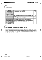
... address is blinking in red. Replace the lamp. • Picture adjustments are incorrectly set. • In the case of transmitting RS-232C commands from a computer during standby, it takes a maximum of the computer to receive the response code. Check • Change the input signal type setting. • The lamp replacement indicator is http://www.sharpusa.com/ . -86 XV-Z10000#Print#p85_92.p65 86 02.10.25, 7:35 PM Troubleshooting Problem Picture is pink (no green...
... address is blinking in red. Replace the lamp. • Picture adjustments are incorrectly set. • In the case of transmitting RS-232C commands from a computer during standby, it takes a maximum of the computer to receive the response code. Check • Change the input signal type setting. • The lamp replacement indicator is http://www.sharpusa.com/ . -86 XV-Z10000#Print#p85_92.p65 86 02.10.25, 7:35 PM Troubleshooting Problem Picture is pink (no green...
Operation Manual
Page 88
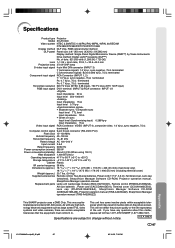
... Remote control, Two AA size batteries, Power cord (11'10", 3.6 m), Terminal cover, Lens cap (attached), SharpVision Manager Software CD-ROM, Projector operation manual, SharpVision Manager operation manual Replacement parts Lamp unit (Lamp/cage module) (BQC-XVZ100001), Remote control (RRMCGA128WJSA), AA size batteries , Power cord (CACCDA010DE01), Terminal cover (CCOVA1985CE02), Lens cap (PCAPHA1056CESA), SharpVision Manager Software CD-ROM (UDSKAA019WJZZ), Projector operation manual (TINS-A440WJZZ), SharpVision Manager operation manual (TINS-A452WJZZ) This SHARP projector uses a DMD Chip...
... Remote control, Two AA size batteries, Power cord (11'10", 3.6 m), Terminal cover, Lens cap (attached), SharpVision Manager Software CD-ROM, Projector operation manual, SharpVision Manager operation manual Replacement parts Lamp unit (Lamp/cage module) (BQC-XVZ100001), Remote control (RRMCGA128WJSA), AA size batteries , Power cord (CACCDA010DE01), Terminal cover (CCOVA1985CE02), Lens cap (PCAPHA1056CESA), SharpVision Manager Software CD-ROM (UDSKAA019WJZZ), Projector operation manual (TINS-A440WJZZ), SharpVision Manager operation manual (TINS-A452WJZZ) This SHARP projector uses a DMD Chip...
Operation Manual
Page 91
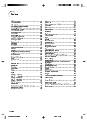
... 13 Replacing the lamp 76 RESIZE button 58 Reversing/Inverting Projected Images 69 RS-232C terminal 23 Save Setting 53 Select Setting 54 Selecting the on-screen display language .......... 34 Signal Info 55 Signal Type 64 SMART STRETCH 59 Special Modes 54 Status 70 STRETCH 59 Supplied accessories 14 Target 50 Temperature warning indicator 74 UNDO button 37 Video System 65 WIRED R/C JACK 24 WIRED REMOTE control input terminal 24 Zoom knob 26 -90 XV-Z10000...
... 13 Replacing the lamp 76 RESIZE button 58 Reversing/Inverting Projected Images 69 RS-232C terminal 23 Save Setting 53 Select Setting 54 Selecting the on-screen display language .......... 34 Signal Info 55 Signal Type 64 SMART STRETCH 59 Special Modes 54 Status 70 STRETCH 59 Supplied accessories 14 Target 50 Temperature warning indicator 74 UNDO button 37 Video System 65 WIRED R/C JACK 24 WIRED REMOTE control input terminal 24 Zoom knob 26 -90 XV-Z10000...
Operation Manual
Page 92
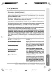
... OF PURCHASE SET FORTH BELOW. THIS WARRANTY GIVES YOU SPECIFIC LEGAL RIGHTS. Model Specific Section (In-Home Service) Your Product Model Number & Description: Warranty Period for this Product: Additional Item(s) Excluded from Warranty Coverage (if any filter. Labor & materials required to remove and reinstall a projector in complex systems including, but not limited to, projectors installed in custom enclosures, projectors connected to third party control and automation...
... OF PURCHASE SET FORTH BELOW. THIS WARRANTY GIVES YOU SPECIFIC LEGAL RIGHTS. Model Specific Section (In-Home Service) Your Product Model Number & Description: Warranty Period for this Product: Additional Item(s) Excluded from Warranty Coverage (if any filter. Labor & materials required to remove and reinstall a projector in complex systems including, but not limited to, projectors installed in custom enclosures, projectors connected to third party control and automation...


