
Service Manual
Page 2
... work . This may cause land separation or may exceed the heat-resistive temperature of tin, the iron tip may cause a breakdown or an accident. XE-A203U/XE-A203A LEAD-FREE SOLDER If the soldering iron tip is confirmed. If different-kind solder remains on the PWB's and the Service Manual mean "Lead-Free...
... work . This may cause land separation or may exceed the heat-resistive temperature of tin, the iron tip may cause a breakdown or an accident. XE-A203U/XE-A203A LEAD-FREE SOLDER If the soldering iron tip is confirmed. If different-kind solder remains on the PWB's and the Service Manual mean "Lead-Free...
Service Manual
Page 3
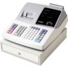
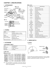
...XE-A203A SPECIFICATIONS - 1 - These keys can be inserted or removed only in the "REG" or "OFF" position. CHAPTER 1. manager (MA) and operator (OP) keys. APPEARANCE Front view Operator display Printer cover Receipt paper Keyboard Drawer Drawer lock Printer Take-up spool Print roller arm Print...key Non-add code/Time display/Subtotal key Total/Amount tender/No Sale key 4. RATING Model Dimensions Weight Power source Power consumption Working temperature XE-A203 13.8 (W) x 16.9 (D) x 11.1 (H) in each key indicates functions or characters which can be used for character entries for ...
...XE-A203A SPECIFICATIONS - 1 - These keys can be inserted or removed only in the "REG" or "OFF" position. CHAPTER 1. manager (MA) and operator (OP) keys. APPEARANCE Front view Operator display Printer cover Receipt paper Keyboard Drawer Drawer lock Printer Take-up spool Print roller arm Print...key Non-add code/Time display/Subtotal key Total/Amount tender/No Sale key 4. RATING Model Dimensions Weight Power source Power consumption Working temperature XE-A203 13.8 (W) x 16.9 (D) x 11.1 (H) in each key indicates functions or characters which can be used for character entries for ...
Service Manual
Page 4
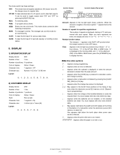
... Color of a transaction when the electronic journal (EJ) memory is nearly full. Number of the installed batteries is not set or out. When you have registered ten times, the display will show "0." (2 3 3 ..... 9 3 0 3 1 3 2 ... ) Receipt function status: The indicator "_" appears in the RCPT OFF...the OP X/Z, REG, or MGR mode. XE-A203U/XE-A203A SPECIFICATIONS - 2 - OP X/Z: To take flash reports. You must replace with new ones immediately. : May appear right below the tenth place when power save mode is effective. : Appears when the print roller arm is not locked. : Appears ...
... Color of a transaction when the electronic journal (EJ) memory is nearly full. Number of the installed batteries is not set or out. When you have registered ten times, the display will show "0." (2 3 3 ..... 9 3 0 3 1 3 2 ... ) Receipt function status: The indicator "_" appears in the RCPT OFF...the OP X/Z, REG, or MGR mode. XE-A203U/XE-A203A SPECIFICATIONS - 2 - OP X/Z: To take flash reports. You must replace with new ones immediately. : May appear right below the tenth place when power save mode is effective. : Appears when the print roller arm is not locked. : Appears ...
Service Manual
Page 5
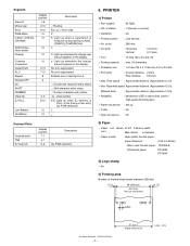
... to 0.08mm Nihon seisi thermal paper : TF50KS-E Oil thermal paper: PD150R, PD160R 3) Logo stamp • No 4) Printing area Number of thermal head heater elements 288 dots (4.75) 48 (288 dots) print area (max.24 characters) (4.75) 0.167 XE-A203U/XE-A203A SPECIFICATIONS - 3 - 57.5±0.5 (Paper dimension) (units : mm) Segment Amount Minus sign Error PGM Mode CASH, CHECK, CHARGE SUB TOTAL...
... to 0.08mm Nihon seisi thermal paper : TF50KS-E Oil thermal paper: PD150R, PD160R 3) Logo stamp • No 4) Printing area Number of thermal head heater elements 288 dots (4.75) 48 (288 dots) print area (max.24 characters) (4.75) 0.167 XE-A203U/XE-A203A SPECIFICATIONS - 3 - 57.5±0.5 (Paper dimension) (units : mm) Segment Amount Minus sign Error PGM Mode CASH, CHECK, CHARGE SUB TOTAL...

Service Manual
Page 6
To unlock it , turn 90 degrees counterclockwise. Battery condition will disappear after New dry batteries are needed. 1. XE-A203U/XE-A203A SPECIFICATIONS - 4 - To lock it , turn to "REG" mode. 3) Release the OLD dry batteries (3 pieces). 4) Insert the NEW dry batteries (3 pieces). 5) Confirm the low battery symbol "L" ...
To unlock it , turn 90 degrees counterclockwise. Battery condition will disappear after New dry batteries are needed. 1. XE-A203U/XE-A203A SPECIFICATIONS - 4 - To lock it , turn to "REG" mode. 3) Release the OLD dry batteries (3 pieces). 4) Insert the NEW dry batteries (3 pieces). 5) Confirm the low battery symbol "L" ...
Service Manual
Page 7
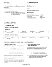
...immediately.) After finalization "F 12.34": Battery is OK. OPTIONS (NONE) 2. SERVICE OPTIONS (NONE) 3. SUPPLIES NO NAME 1 Thermal roll paper 4. MASTER RESETTING Master resetting clears the entire memory and resumes initial values. Master resetting can be without clearing memory. ...lost and the machine does not work properly after the "POWER OFF". 10. XE-A203U/XE-A203A OPTIONS - 5 - [Display sample] " 0.00": Battery is OK. SD MEMORY CARD [Device] SD Card (Version. 1.01) [Outline] XE-A203U has a SD Memory Card slot. [Specidications] 1) Variable clock rate : ...
...immediately.) After finalization "F 12.34": Battery is OK. OPTIONS (NONE) 2. SERVICE OPTIONS (NONE) 3. SUPPLIES NO NAME 1 Thermal roll paper 4. MASTER RESETTING Master resetting clears the entire memory and resumes initial values. Master resetting can be without clearing memory. ...lost and the machine does not work properly after the "POWER OFF". 10. XE-A203U/XE-A203A OPTIONS - 5 - [Display sample] " 0.00": Battery is OK. SD MEMORY CARD [Device] SD Card (Version. 1.01) [Outline] XE-A203U has a SD Memory Card slot. [Specidications] 1) Variable clock rate : ...
Service Manual
Page 8
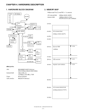
... 08000h External RAM 128KByte /CS2 27000h 28000h USB controller 30000h Segment Latch Address /CS1 /CS0 80000h B0000h CPU internal MASK ROM 320KByte B0000h-FFFFFh FFFFFh XE-A203U/XE-A203A HARDWARE DESCRIPTION - 6 - HARDWARE DESCRIPTION 1. MEMORY MAP 1MByte mode/The CS area PM13 = 1 is selected. HARDWARE BLOCK DIAGRAM POWER DRY Battery 5.8V 5.0V BUZZER 3.3V...
... 08000h External RAM 128KByte /CS2 27000h 28000h USB controller 30000h Segment Latch Address /CS1 /CS0 80000h B0000h CPU internal MASK ROM 320KByte B0000h-FFFFFh FFFFFh XE-A203U/XE-A203A HARDWARE DESCRIPTION - 6 - HARDWARE DESCRIPTION 1. MEMORY MAP 1MByte mode/The CS area PM13 = 1 is selected. HARDWARE BLOCK DIAGRAM POWER DRY Battery 5.8V 5.0V BUZZER 3.3V...
Service Manual
Page 9
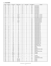
... CONTROLLER SRAM UNUSED WRITE STROBE SIGNAL UNUSED READ STROBE SIGNAL UNUSED UNUSED UNUSED VCC PULL UP DRAWER DRIVE SIGNAL SD CLK SD RXD SD TXD XE-A203U/XE-A203A HARDWARE DESCRIPTION - 7 -
... CONTROLLER SRAM UNUSED WRITE STROBE SIGNAL UNUSED READ STROBE SIGNAL UNUSED UNUSED UNUSED VCC PULL UP DRAWER DRIVE SIGNAL SD CLK SD RXD SD TXD XE-A203U/XE-A203A HARDWARE DESCRIPTION - 7 -
Service Manual
Page 10
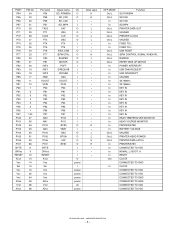
...: L / BOOT: H RESET CLOCK CONNECTED TO GND CLOCK CONNECTED TO VDD CONNECTED TO VDD CONNECTED TO GND CONNECTED TO GND CONNECTED TO VDD CONNECTED TO VDD XE-A203U/XE-A203A HARDWARE DESCRIPTION - 8 - PORT P64 P65 P66 P67 P70 P71 P72 P73 P74 P75 P76 P77 P80 P81 P82 P83 P84 P85 P86 P87 P90...
...: L / BOOT: H RESET CLOCK CONNECTED TO GND CLOCK CONNECTED TO VDD CONNECTED TO VDD CONNECTED TO GND CONNECTED TO GND CONNECTED TO VDD CONNECTED TO VDD XE-A203U/XE-A203A HARDWARE DESCRIPTION - 8 - PORT P64 P65 P66 P67 P70 P71 P72 P73 P74 P75 P76 P77 P80 P81 P82 P83 P84 P85 P86 P87 P90...
Service Manual
Page 11
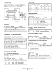
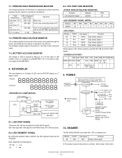
...7. PRINTER CONTROL 6-1. CPU PORT Use signal Function 89 P107 STRB1# Printer STB1# 94 P102 STRB2# Printer STB2# 30 P70 DAT Printer print data 28 P72 PCLK Printer forwarding clock 90 P106 LATCH# Printer data latch 91 P105 VPON Printer head motor power 6-3. PAPER TAKE UP ... Function 97 AN0/P100 TM Printer head temperature monitor 95 AN1/P101 VPTEST Printer head voltage monitor 93 AN3/P103 VBAT Battery voltage monitor XE-A203U/XE-A203A HARDWARE DESCRIPTION - 9 - PORT Strobe signal Function 6 P91 /S4 Printer out of paper detection (It reads according to the /CS1...
...7. PRINTER CONTROL 6-1. CPU PORT Use signal Function 89 P107 STRB1# Printer STB1# 94 P102 STRB2# Printer STB2# 30 P70 DAT Printer print data 28 P72 PCLK Printer forwarding clock 90 P106 LATCH# Printer data latch 91 P105 VPON Printer head motor power 6-3. PAPER TAKE UP ... Function 97 AN0/P100 TM Printer head temperature monitor 95 AN1/P101 VPTEST Printer head voltage monitor 93 AN3/P103 VBAT Battery voltage monitor XE-A203U/XE-A203A HARDWARE DESCRIPTION - 9 - PORT Strobe signal Function 6 P91 /S4 Printer out of paper detection (It reads according to the /CS1...
Service Manual
Page 12
...and divided by the thermistor for the printer is judged as follow: 55ms (max) 50ms (min) XE-A203U/XE-A203A HARDWARE DESCRIPTION - 10 - PORT 80 P10 79 P11 78 P12 77 P13 Use signal Function KST0...A203A is of 7 digits of a drawer port. For an A/D value of VDD is judged as LED DIGIT signals. POWER TRANS. BATTERY VOLTAGE MONITOR The voltage of 189 (3.69V) or less, it is inputted to the AN1 pin. CPU PORT AND REGISTER... 929~1023 Motor lock -10°C ~ Less than 0°C 869~928 Print in the conduction time at 0°C. 0°C ~ Less than 70°C 232~868...
...and divided by the thermistor for the printer is judged as follow: 55ms (max) 50ms (min) XE-A203U/XE-A203A HARDWARE DESCRIPTION - 10 - PORT 80 P10 79 P11 78 P12 77 P13 Use signal Function KST0...A203A is of 7 digits of a drawer port. For an A/D value of VDD is judged as LED DIGIT signals. POWER TRANS. BATTERY VOLTAGE MONITOR The voltage of 189 (3.69V) or less, it is inputted to the AN1 pin. CPU PORT AND REGISTER... 929~1023 Motor lock -10°C ~ Less than 0°C 869~928 Print in the conduction time at 0°C. 0°C ~ Less than 70°C 232~868...
Service Manual
Page 13
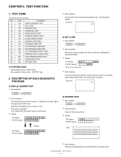
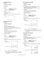
...** *** 4 End of testing The test will shift in steps of testing You can exit the test mode by pressing any key. End print: 101 3) PRINTER TEST 1 Key operation 102 RCPT/PO 2 Test procedure 3 lines of 24 Z's are as follows. TEST FUNCTION 1. Code... operation 100 RCPT/PO 2 Test procedure The decimal point will automatically be terminated after the printer prints. XE-A203U/XE-A203A TEST FUNCTION - 11 - The following is repeated. The printer prints as follows. This mode is printed. NO. At the same time, the buzzer sounds continuously. 3 Display OP display: 1. ...
...** *** 4 End of testing The test will shift in steps of testing You can exit the test mode by pressing any key. End print: 101 3) PRINTER TEST 1 Key operation 102 RCPT/PO 2 Test procedure 3 lines of 24 Z's are as follows. TEST FUNCTION 1. Code... operation 100 RCPT/PO 2 Test procedure The decimal point will automatically be terminated after the printer prints. XE-A203U/XE-A203A TEST FUNCTION - 11 - The following is repeated. The printer prints as follows. This mode is printed. NO. At the same time, the buzzer sounds continuously. 3 Display OP display: 1. ...
Service Manual
Page 14
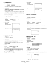
... "PGM" position again. When the data are in the proper sequence. End print: yymmdd-hhmmss 107 (*) yy = year mm = month dd = day hh = hour mm = min ss = sec XE-A203U/XE-A203A TEST FUNCTION - 12 - If the test is completed normally, the end print is made. m m s s (*) hh = hour mm = min ss... = sec 4 Check that the positions are printed and the test mode will terminated. Check that A) Check "-" blinks at an...
... "PGM" position again. When the data are in the proper sequence. End print: yymmdd-hhmmss 107 (*) yy = year mm = month dd = day hh = hour mm = min ss = sec XE-A203U/XE-A203A TEST FUNCTION - 12 - If the test is completed normally, the end print is made. m m s s (*) hh = hour mm = min ss... = sec 4 Check that the positions are printed and the test mode will terminated. Check that A) Check "-" blinks at an...
Service Manual
Page 15
... test program checks that The drawer opens normally. 5 End of testing The test will automatically be terminated and the printer prints as follows. When an error occurs: RAM ERROR X *****h 120 ROM XE-A203U/XE-A203A TEST FUNCTION - 13 - a) Data in the test area is tested in the following procedure. The lower two digits of...
... test program checks that The drawer opens normally. 5 End of testing The test will automatically be terminated and the printer prints as follows. When an error occurs: RAM ERROR X *****h 120 ROM XE-A203U/XE-A203A TEST FUNCTION - 13 - a) Data in the test area is tested in the following procedure. The lower two digits of...
Service Manual
Page 16
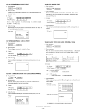
...Key operation 550 RCPT/PO 2 Test procedure Check to the error print.) XE-A203U/XE-A203A TEST FUNCTION - 14 - POPUP display: 4 End of testing The test will automatically be terminated and the printer prints as follows. Ver. 12) AD CONVERSION PORT TEST 1 Key ... X **** POPUP display: (*) X = 1: Head temperature X = 2: Head voltage X = 3: Battery voltage A /D value 4 End of testing When any key is pressed, the SD card register is read error 3 Display OP display: 620 POPUP display: X-Y X-Y (*) X = SD card detection 1 SD card YES 0 : SD card NO (*) Y = WP detection 1 ...
...Key operation 550 RCPT/PO 2 Test procedure Check to the error print.) XE-A203U/XE-A203A TEST FUNCTION - 14 - POPUP display: 4 End of testing The test will automatically be terminated and the printer prints as follows. Ver. 12) AD CONVERSION PORT TEST 1 Key ... X **** POPUP display: (*) X = 1: Head temperature X = 2: Head voltage X = 3: Battery voltage A /D value 4 End of testing When any key is pressed, the SD card register is read error 3 Display OP display: 620 POPUP display: X-Y X-Y (*) X = SD card detection 1 SD card YES 0 : SD card NO (*) Y = WP detection 1 ...

Service Manual
Page 17
CIRCUIT DIAGRAM AND PWB LAYOUT ■ MAIN PWB 1/4 XE-A203U/XE-A203A CIRCUIT DIAGRAM AND PWB LAYOUT - 15 - CPU CIRCUIT VCC D ...3 2 C13 2 P96 2 P95 1 1000pF 2 2 P94 P93 VDD 2 P92 2 P91 2 P90 R58 1K /RESUSB 2 10K 10K R50 R42 XE-A20W ONLY DAT 2 10K CLK 2 D1 R40 B +BZ1 R52 PIEZO BZ 10K D0 D1 D2 D3 D4 D5 D6 D7 2 3 4 5 A0 ...C21 27pF 32.768KHz 1 2 3 /DREQUSB /INTUSB X3 MOTOR /POFF 2 3 VCC 1 1SS133 VCC3 D0 D1 C24 D2 D3 D4 0.1uF D5 D6 D7 10K R40 XE-A203U/A ONLY 1 2 3 4 5 6 7 8 9 10 11 2 1 VDD + C17 C16 0.1uF IC7 A0 2 A1 3 A2 4 A3 5 A4 ...
CIRCUIT DIAGRAM AND PWB LAYOUT ■ MAIN PWB 1/4 XE-A203U/XE-A203A CIRCUIT DIAGRAM AND PWB LAYOUT - 15 - CPU CIRCUIT VCC D ...3 2 C13 2 P96 2 P95 1 1000pF 2 2 P94 P93 VDD 2 P92 2 P91 2 P90 R58 1K /RESUSB 2 10K 10K R50 R42 XE-A20W ONLY DAT 2 10K CLK 2 D1 R40 B +BZ1 R52 PIEZO BZ 10K D0 D1 D2 D3 D4 D5 D6 D7 2 3 4 5 A0 ...C21 27pF 32.768KHz 1 2 3 /DREQUSB /INTUSB X3 MOTOR /POFF 2 3 VCC 1 1SS133 VCC3 D0 D1 C24 D2 D3 D4 0.1uF D5 D6 D7 10K R40 XE-A203U/A ONLY 1 2 3 4 5 6 7 8 9 10 11 2 1 VDD + C17 C16 0.1uF IC7 A0 2 A1 3 A2 4 A3 5 A4 ...

Service Manual
Page 18
... R71 56KF 8 3 + 2 - 4 1 IC8A BA10393 1 R75 5.1KF VO 1,3 TCOFF 3 4 3 VO 2,3 8 5 + 7 6 - 4 IC8B BA10393 2 1 2/4 VP NOT INSTALL C28 0.1uF CN4 1 2 EH-2A 2 1 MOTOR R76 1 1K Q1 2SD2212 D MOTOR 3 XE-A203U/XE-A203A CIRCUIT DIAGRAM AND PWB LAYOUT - 16 -
... R71 56KF 8 3 + 2 - 4 1 IC8A BA10393 1 R75 5.1KF VO 1,3 TCOFF 3 4 3 VO 2,3 8 5 + 7 6 - 4 IC8B BA10393 2 1 2/4 VP NOT INSTALL C28 0.1uF CN4 1 2 EH-2A 2 1 MOTOR R76 1 1K Q1 2SD2212 D MOTOR 3 XE-A203U/XE-A203A CIRCUIT DIAGRAM AND PWB LAYOUT - 16 -

Service Manual
Page 19
XE-A203U/XE-A203A CIRCUIT DIAGRAM AND PWB LAYOUT - 17 - 8 7 6 5 4 3 2 1 POWER CIRCUIT 3/4 F2 Q1:HEAT SINK 3C 3C 4 D5 VP 3.15A IPEAK>12A :100% D CN7 2 C42 3- +1 MYLAR Q5 L1 2 ...
XE-A203U/XE-A203A CIRCUIT DIAGRAM AND PWB LAYOUT - 17 - 8 7 6 5 4 3 2 1 POWER CIRCUIT 3/4 F2 Q1:HEAT SINK 3C 3C 4 D5 VP 3.15A IPEAK>12A :100% D CN7 2 C42 3- +1 MYLAR Q5 L1 2 ...

Service Manual
Page 20
XE-A203U/XE-A203A CIRCUIT DIAGRAM AND PWB LAYOUT - 18 - 8 7 6 5 4 3 SD CARD CIRCUIT S:1pin VCC3 VCC3 D:2,3,4,5pin 3 5 G:6pin 1 2 4 1 14Pin : VCC3 + C66 1 6 7Pin : GND 100uF/50V + C56 D VCC3 2 Q9 HAT1089C ...
XE-A203U/XE-A203A CIRCUIT DIAGRAM AND PWB LAYOUT - 18 - 8 7 6 5 4 3 SD CARD CIRCUIT S:1pin VCC3 VCC3 D:2,3,4,5pin 3 5 G:6pin 1 2 4 1 14Pin : VCC3 + C66 1 6 7Pin : GND 100uF/50V + C56 D VCC3 2 Q9 HAT1089C ...

Service Manual
Page 24
XE-A203U/XE-A203A CIRCUIT DIAGRAM AND PWB LAYOUT - 22 - 8 7 6 5 4 3 2 ■ MODE SWITCH CIRCUIT D SW1 MODE SWITCH 0 GND 000 /VON 00 C GND 1 2 3 4 5 6 7 8 9 10 /S7 /S6 /S5 /S4 /S3 MOR/S2 /S1 /S0 /RESET 12 11 10 9 8 7 6 5 4 3 2 1 B CN1 P:2.0mm HOLE ONLY FOR KEY I/F BOARD 13 A 8 7 6 5 4 3 2 1 1/1 D C B A 1
XE-A203U/XE-A203A CIRCUIT DIAGRAM AND PWB LAYOUT - 22 - 8 7 6 5 4 3 2 ■ MODE SWITCH CIRCUIT D SW1 MODE SWITCH 0 GND 000 /VON 00 C GND 1 2 3 4 5 6 7 8 9 10 /S7 /S6 /S5 /S4 /S3 MOR/S2 /S1 /S0 /RESET 12 11 10 9 8 7 6 5 4 3 2 1 B CN1 P:2.0mm HOLE ONLY FOR KEY I/F BOARD 13 A 8 7 6 5 4 3 2 1 1/1 D C B A 1


