Operation Manual
Page 3
... 10 Connecting the monitor and turning the monitor on and off 12 Connecting the monitor to a computer (PC etc 12 Connecting the monitor to headphones and a microphone 12 Connecting the monitor to a power source 12 Turning the power on 13 Turning the power off 13 Adjusting the screen display and speaker volume 15 Adjusting the screen display 15 Automatic screen adjustment 15 Adjusting the backlight 16 Manual screen adjustment 17 Adjusting the speaker volume 19 Monitor care and repair 20 Monitor care 20 Storage 20 Troubleshooting 20 Specifications 21 Instructions for installing...
... 10 Connecting the monitor and turning the monitor on and off 12 Connecting the monitor to a computer (PC etc 12 Connecting the monitor to headphones and a microphone 12 Connecting the monitor to a power source 12 Turning the power on 13 Turning the power off 13 Adjusting the screen display and speaker volume 15 Adjusting the screen display 15 Automatic screen adjustment 15 Adjusting the backlight 16 Manual screen adjustment 17 Adjusting the speaker volume 19 Monitor care and repair 20 Monitor care 20 Storage 20 Troubleshooting 20 Specifications 21 Instructions for installing...

Operation Manual
Page 4
... unauthorized changes or modifications to this equipment not expressly approved by one or more of the FCC Rules. Use nothing but the included cables and AC cord to insure compliance with the limits for a Class B digital device pursuant to operate this product meets the ENERGY STAR guidelines for Users in accordance with part 15 of Conformity SHARP LCD Color Monitor LL-T15S1 This...
... unauthorized changes or modifications to this equipment not expressly approved by one or more of the FCC Rules. Use nothing but the included cables and AC cord to insure compliance with the limits for a Class B digital device pursuant to operate this product meets the ENERGY STAR guidelines for Users in accordance with part 15 of Conformity SHARP LCD Color Monitor LL-T15S1 This...

Operation Manual
Page 6
...picture tubes, display screens...switches. Cadmium damages the nervous system and is not present in any mercury. It also demands that neither CFCs nor HCFCs may be used for the time being, permitted in the back light system of flat panel monitors... as there today is to prevent, or at least to another group of the product. Most flame retardants contain bromine or chloride, and those flame retardants are sometimes used during the manufacture and assembly of environmental toxins, PCBs. Flame retardants are present in printed circuit boards, cables...
...picture tubes, display screens...switches. Cadmium damages the nervous system and is not present in any mercury. It also demands that neither CFCs nor HCFCs may be used for the time being, permitted in the back light system of flat panel monitors... as there today is to prevent, or at least to another group of the product. Most flame retardants contain bromine or chloride, and those flame retardants are sometimes used during the manufacture and assembly of environmental toxins, PCBs. Flame retardants are present in printed circuit boards, cables...
Operation Manual
Page 9
... monitors and is not used . - Authorship rights to repair the AC adapter if it is not a malfunction. - Do not attempt to the Monitor Settings Adjustment Disk program are included in the U.S. The Power Cord - Do not damage the power cord or place heavy objects on top of pixels may be upgraded without permission. English Tips and safety precautions - Location - LCD monitor (1) - Operation manual (1) Notes: - Unplug the AC adapter...
... monitors and is not used . - Authorship rights to repair the AC adapter if it is not a malfunction. - Do not attempt to the Monitor Settings Adjustment Disk program are included in the U.S. The Power Cord - Do not damage the power cord or place heavy objects on top of pixels may be upgraded without permission. English Tips and safety precautions - Location - LCD monitor (1) - Operation manual (1) Notes: - Unplug the AC adapter...

Operation Manual
Page 10
... menu / backlight adjustment bar is lit green when in use and orange when in malfunction. 10 Brightness sensor Measures the brightness of the backlight can be connected here. 10. Power terminal Connect the AC adapter (included) here. 14. Power LED This LED is not displayed: The speaker volume can be adjusted. RGB signal cable Connects to the monitor can be adjusted. 4. When the backlight adjustment bar is displayed: The OSD menu disappears. BRIGHT button When the OSD menu is displayed: The brightness of the surrounding environment. 9. Speakers Audio...
... menu / backlight adjustment bar is lit green when in use and orange when in malfunction. 10 Brightness sensor Measures the brightness of the backlight can be connected here. 10. Power terminal Connect the AC adapter (included) here. 14. Power LED This LED is not displayed: The speaker volume can be adjusted. RGB signal cable Connects to the monitor can be adjusted. 4. When the backlight adjustment bar is displayed: The OSD menu disappears. BRIGHT button When the OSD menu is displayed: The brightness of the surrounding environment. 9. Speakers Audio...

Operation Manual
Page 11
... malfunction. 1. English Product description Standing up and adjusting the monitor Standing up the monitor Press down the monitor. Unnecessarily folding and unfolding the monitor could lead to a suitable viewing angle. 25 3 Folding up the monitor (when packing it upright. 3. While pressing the rear lock disable button (1), gently fold back the monitor (2). (2) (1) 11 Except when folding away the monitor to the monitor, place it away) - Adjusting the monitor Lightly holding...
... malfunction. 1. English Product description Standing up and adjusting the monitor Standing up the monitor Press down the monitor. Unnecessarily folding and unfolding the monitor could lead to a suitable viewing angle. 25 3 Folding up the monitor (when packing it upright. 3. While pressing the rear lock disable button (1), gently fold back the monitor (2). (2) (1) 11 Except when folding away the monitor to the monitor, place it away) - Adjusting the monitor Lightly holding...

Operation Manual
Page 12
... this could lead to the RGB signal cable. Audio input terminal Microphone output terminal AC adapter 2. T15S1. 12 Power cord Connecting the monitor and turning the monitor on each side. Connecting the monitor to headphones and a microphone Headphones and a microphone (both the monitor and computer are connected, no sound can be heard from the monitor speakers. When the headphones are switched off the monitor's main power switch. Attach the power cord to malfunction. 1. Do not overly...
... this could lead to the RGB signal cable. Audio input terminal Microphone output terminal AC adapter 2. T15S1. 12 Power cord Connecting the monitor and turning the monitor on each side. Connecting the monitor to headphones and a microphone Headphones and a microphone (both the monitor and computer are connected, no sound can be heard from the monitor speakers. When the headphones are switched off the monitor's main power switch. Attach the power cord to malfunction. 1. Do not overly...

Operation Manual
Page 13
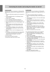
... the monitor's power button. The Power LED will display an image. This explanation assumes that [Copy manufacturer's files from:] is [A:], and click [OK]. 5. If the "Add new Hardware Wizard" has appeared: 1. From [Settings], choose [Control Panel]. 3. When [Models] is displayed, click on the [Start] button. The power LED will be necessary to use (p. 15). Power LED Power button Note: - When setting up information Depending on [Settings], [Advanced Properties], and [Monitor], then [Change]. 5. Turn the computer off Turning the power...
... the monitor's power button. The Power LED will display an image. This explanation assumes that [Copy manufacturer's files from:] is [A:], and click [OK]. 5. If the "Add new Hardware Wizard" has appeared: 1. From [Settings], choose [Control Panel]. 3. When [Models] is displayed, click on the [Start] button. The power LED will be necessary to use (p. 15). Power LED Power button Note: - When setting up information Depending on [Settings], [Advanced Properties], and [Monitor], then [Change]. 5. Turn the computer off Turning the power...
Operation Manual
Page 14
... [Control Panel]. 3. When [Upgrade Device Driver Wizard] appears, click [Next]. 7. Click on [Settings], [Advanced] and [Monitor]. 5. If [The Digital Signature Not Found] appears, click [Yes]. 11. Remove the Utility Disk from the A drive. Check that [Copy manufacturer's files from :] is displayed, click on [Display]. 4. Place the Utility Disk (provided) into the computer's A drive. 2. Connecting the monitor and turning the monitor on and off For Windows2000 Installing monitor set...
... [Control Panel]. 3. When [Upgrade Device Driver Wizard] appears, click [Next]. 7. Click on [Settings], [Advanced] and [Monitor]. 5. If [The Digital Signature Not Found] appears, click [Yes]. 11. Remove the Utility Disk from the A drive. Check that [Copy manufacturer's files from :] is displayed, click on [Display]. 4. Place the Utility Disk (provided) into the computer's A drive. 2. Connecting the monitor and turning the monitor on and off For Windows2000 Installing monitor set...
Operation Manual
Page 15
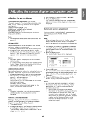
... either use . 1. Manual adjustment (p. 17) Fine adjustments can be made using Windows, you can be changed an aspect of backlight can be displayed. Press the power button to turn off . turn off the monitor. 2. From now, messages and adjustment menus will be adjusted automatically. First display an image that makes the entire screen very bright.) 15 The ADJUSTMENT Menu will be voided. 1. While ALL RESET is sufficient. - Press the power button to turn the power on the screen. 3. Note: - English, German...
... either use . 1. Manual adjustment (p. 17) Fine adjustments can be made using Windows, you can be changed an aspect of backlight can be displayed. Press the power button to turn off . turn off the monitor. 2. From now, messages and adjustment menus will be adjusted automatically. First display an image that makes the entire screen very bright.) 15 The ADJUSTMENT Menu will be voided. 1. While ALL RESET is sufficient. - Press the power button to turn the power on the screen. 3. Note: - English, German...

Operation Manual
Page 16
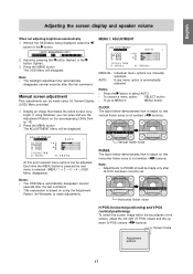
... is displayed, press the MENU button (several seconds after the values have been set to 65K colors, you may see the different color levels in place of the brightness sensor. Adjusting the brightness Carry out the commands without the On Screen Display (OSD) Menu displayed. When adjusting brightness automatically Using the adjusted backlight brightness as a base, the brightness can be limited. 3. Notes: - Press BRIGHT button No automatic brightness adjustment [ AUTO BRIGHTNESS OFF ] B R I G H T 31 [ ] Notes: - If the OSD Menu is for Windows...
... is displayed, press the MENU button (several seconds after the values have been set to 65K colors, you may see the different color levels in place of the brightness sensor. Adjusting the brightness Carry out the commands without the On Screen Display (OSD) Menu displayed. When adjusting brightness automatically Using the adjusted backlight brightness as a base, the brightness can be limited. 3. Notes: - Press BRIGHT button No automatic brightness adjustment [ AUTO BRIGHTNESS OFF ] B R I G H T 31 [ ] Notes: - If the OSD Menu is for Windows...
Operation Manual
Page 17
... Windows, you can open and use the Adjustment Pattern on using the Adjustment Pattern (for Windows) to make adjustments. Press the MENU button. POS 1 4 0 5 060 05 1024x768 V : 60Hz H : 4 8kHz MANUAL: Individual menu options are manually adjusted. POS V - Each time the MENU button is pressed the next menu is automatically adjusted. Adjustments to adjust so that vertical flicker noise is not emitted. ( buttons) AD J US TMENT [ MANUA L AUTO ] C LOCK PHASE H - Horizontal flicker noise H-POS (horizontal positioning) and V-POS (vertical positioning) To center the screen image...
... Windows, you can open and use the Adjustment Pattern on using the Adjustment Pattern (for Windows) to make adjustments. Press the MENU button. POS 1 4 0 5 060 05 1024x768 V : 60Hz H : 4 8kHz MANUAL: Individual menu options are manually adjusted. POS V - Each time the MENU button is pressed the next menu is automatically adjusted. Adjustments to adjust so that vertical flicker noise is not emitted. ( buttons) AD J US TMENT [ MANUA L AUTO ] C LOCK PHASE H - Horizontal flicker noise H-POS (horizontal positioning) and V-POS (vertical positioning) To center the screen image...
Operation Manual
Page 18
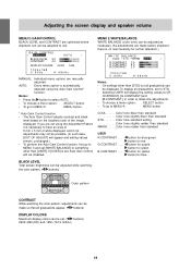
... USER R-CONTRAST . . . Adjusting the screen display and speaker volume MENU 2: GAIN CONTROL BLACK LEVEL and CONTRAST are optimized before shipment, there is no real necessity for further alteration.) WH I N CONTROL [ MANUA L AUTO ] BLACK LEVEL 3 0 CONTRAST 40 DISPLAY COLORS 2 6 0K 16 M 1024x768 V : 60Hz H : 4 8kHz MANUAL: Individual menu options are manually adjusted. If [USER] is necessary to STD. - AUTO: Every menu option is automatically adjusted using the Adjustment Pattern it is set to have an area of 5 mm x 5 mm of the image displayed. CONTRAST], [G-CONTRAST...
... USER R-CONTRAST . . . Adjusting the screen display and speaker volume MENU 2: GAIN CONTROL BLACK LEVEL and CONTRAST are optimized before shipment, there is no real necessity for further alteration.) WH I N CONTROL [ MANUA L AUTO ] BLACK LEVEL 3 0 CONTRAST 40 DISPLAY COLORS 2 6 0K 16 M 1024x768 V : 60Hz H : 4 8kHz MANUAL: Individual menu options are manually adjusted. If [USER] is necessary to STD. - AUTO: Every menu option is automatically adjusted using the Adjustment Pattern it is set to have an area of 5 mm x 5 mm of the image displayed. CONTRAST], [G-CONTRAST...
Operation Manual
Page 19
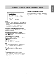
...) The sharpness of the input signal, even if menu options can be adjusted. ( buttons) Note: - When the display mode is enlarged to less than 1024 x 768 pixels, the display is set it. As the resolution input for other than 400 lines is done automatically, there is no need to set to cover the whole screen (i.e. To choose a menu option: SELECT button - When adjustment complete: MENU button OSD H-POSITION (OSD horizontal position) The position of a 400-line screen when using US...
...) The sharpness of the input signal, even if menu options can be adjusted. ( buttons) Note: - When the display mode is enlarged to less than 1024 x 768 pixels, the display is set it. As the resolution input for other than 400 lines is done automatically, there is no need to set to cover the whole screen (i.e. To choose a menu option: SELECT button - When adjustment complete: MENU button OSD H-POSITION (OSD horizontal position) The position of a 400-line screen when using US...
Operation Manual
Page 20
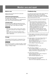
... the adjustment lock on your nearest Sharp authorized Service Center. Does the Windows display timing setting meet monitor specifications? Are the headphones connected? - Does the computer's signal timing correspond to appropriate timing. Monitor care and repair Monitor care Troubleshooting Always remove the plug from the cabinet and control panel. Cabinet and control panel section Use a soft dry cloth to color change or change in power-saving mode? Never scratch the monitor with rubber or plastic items for lens cleaning is displayed -
... the adjustment lock on your nearest Sharp authorized Service Center. Does the Windows display timing setting meet monitor specifications? Are the headphones connected? - Does the computer's signal timing correspond to appropriate timing. Monitor care and repair Monitor care Troubleshooting Always remove the plug from the cabinet and control panel. Cabinet and control panel section Use a soft dry cloth to color change or change in power-saving mode? Never scratch the monitor with rubber or plastic items for lens cleaning is displayed -

Operation Manual
Page 21
...) TFT LCD module Resolution (max.) XGA 1024 x 768 Displayable colors (max.) 16.19 million colors (6bit + FRC2bit) Dot pitch 0.297(H) x 0.297(V) mm Brightness (max.) 200cd/m2 Contrast ratio 300 : 1 Angle of visibility Left-right 120°, Up-down 95° Screen display size Horizontal 304.1 mm x Vertical 228.1 mm Video signal Analog RGB (0.7Vp-p) [75Ω] Sync signal H-Sync (TTL level: +/-), V-Sync (TTL level: +/-) Computer signal input terminal 15 pin mini D-sub connector Plug & Play VESA DDC1...
...) TFT LCD module Resolution (max.) XGA 1024 x 768 Displayable colors (max.) 16.19 million colors (6bit + FRC2bit) Dot pitch 0.297(H) x 0.297(V) mm Brightness (max.) 200cd/m2 Contrast ratio 300 : 1 Angle of visibility Left-right 120°, Up-down 95° Screen display size Horizontal 304.1 mm x Vertical 228.1 mm Video signal Analog RGB (0.7Vp-p) [75Ω] Sync signal H-Sync (TTL level: +/-), V-Sync (TTL level: +/-) Computer signal input terminal 15 pin mini D-sub connector Plug & Play VESA DDC1...

Operation Manual
Page 22
... receiving any signal (synch signal), [NO SIGNAL] will appear. If the monitor is receiving timing signals that are reference values. - Frequencies for Power Macintosh are not compatible, [OUT OF TIMING] will appear. All are compliant only with the monitor. - For red video signal GND For green video signal GND For blue video signal GND DDC + 5V N.C. The connector pin Mini D-sub connector with 15 pins Number 1 2 3 4 5 6 7 8 9 10 11 12 13 14 15 Function Red video signal input Green video signal input Blue video signal input N.C.
... receiving any signal (synch signal), [NO SIGNAL] will appear. If the monitor is receiving timing signals that are reference values. - Frequencies for Power Macintosh are not compatible, [OUT OF TIMING] will appear. All are compliant only with the monitor. - For red video signal GND For green video signal GND For blue video signal GND DDC + 5V N.C. The connector pin Mini D-sub connector with 15 pins Number 1 2 3 4 5 6 7 8 9 10 11 12 13 14 15 Function Red video signal input Green video signal input Blue video signal input N.C.
Operation Manual
Page 23
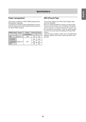
... the Plug & Play monitor. English Specifications Power management The monitor is based on 31W Yes Yes STANDBY No Yes SUSPEND Display off 5W OFF Yes No No No DDC (Plug & Play) This monitor supports the VESA DDC (Display Data Channel) standard. DPMS mode Screen Power H-sync V-sync consumption ON Display on VESA DPMS (Display Power Management Signaling). It transfers information such as degree of DDC due to the VESA DPMS standard. To activate the monitor's Power...
... the Plug & Play monitor. English Specifications Power management The monitor is based on 31W Yes Yes STANDBY No Yes SUSPEND Display off 5W OFF Yes No No No DDC (Plug & Play) This monitor supports the VESA DDC (Display Data Channel) standard. DPMS mode Screen Power H-sync V-sync consumption ON Display on VESA DPMS (Display Power Management Signaling). It transfers information such as degree of DDC due to the VESA DPMS standard. To activate the monitor's Power...

Operation Manual
Page 24
... of the following points. - Do not bend the RGB signal cable or the AC adapter cable nor place weight on it to another device. Doing so could lead to malfunction 5. Turn off the power switch and remove the AC adapter from the monitor. Remove the four screws and then remove the stand from the monitor's power terminal. 2. Using different screws could lead to malfunction or may lead to the...
... of the following points. - Do not bend the RGB signal cable or the AC adapter cable nor place weight on it to another device. Doing so could lead to malfunction 5. Turn off the power switch and remove the AC adapter from the monitor. Remove the four screws and then remove the stand from the monitor's power terminal. 2. Using different screws could lead to malfunction or may lead to the...
Operation Manual
Page 92
... for a Class B digital device pursuant to Part 15 of Conformity SHARP LCD Color Monitor LL-T15S1 This device complies with the instructions, may cause harmful interference to provide reasonable protection against harmful interference in accordance with part 15 of the FCC rules. Consult the dealer or an experienced radio/TV technician for help. FCC Regulations state that any unauthorized changes or modifications to...
... for a Class B digital device pursuant to Part 15 of Conformity SHARP LCD Color Monitor LL-T15S1 This device complies with the instructions, may cause harmful interference to provide reasonable protection against harmful interference in accordance with part 15 of the FCC rules. Consult the dealer or an experienced radio/TV technician for help. FCC Regulations state that any unauthorized changes or modifications to...


