Operation Manual
Page 3
... technician for help. Declaration of Conformity SHARP LCD Color Monitor LL-T15G4-H/LL-T15G4-B This device complies with the limits for a Class B digital device pursuant to comply with part 15 of the FCC Rules. This product utilizes tin-lead solder, and fluorescent lamp containing a small amount of loss or theft, please record the monitor's model and serial numbers in the space provided. Connect the equipment...
... technician for help. Declaration of Conformity SHARP LCD Color Monitor LL-T15G4-H/LL-T15G4-B This device complies with the limits for a Class B digital device pursuant to comply with part 15 of the FCC Rules. This product utilizes tin-lead solder, and fluorescent lamp containing a small amount of loss or theft, please record the monitor's model and serial numbers in the space provided. Connect the equipment...

Operation Manual
Page 7
... the monitor to a power source 12 Turning the power on 13 Changing between input terminals 13 Turning the power off 13 Adjusting the screen display and speaker volume 14 Adjusting the backlight 14 Adjusting the speaker volume 15 Setting display mode 15 Adjusting the screen display (When using an analog signal 16 Automatic screen adjustment 16 Manual screen adjustment 17 Adjusting the screen display (When using a digital signal 20 Monitor care 22 Monitor care 22 Storage 22 Troubleshooting 22 Specifications 23 Installing set-up information and the ICC profile (For Windows 26...
... the monitor to a power source 12 Turning the power on 13 Changing between input terminals 13 Turning the power off 13 Adjusting the screen display and speaker volume 14 Adjusting the backlight 14 Adjusting the speaker volume 15 Setting display mode 15 Adjusting the screen display (When using an analog signal 16 Automatic screen adjustment 16 Manual screen adjustment 17 Adjusting the screen display (When using a digital signal 20 Monitor care 22 Monitor care 22 Storage 22 Troubleshooting 22 Specifications 23 Installing set-up information and the ICC profile (For Windows 26...
Operation Manual
Page 8
... see the screen. Insert the power plug directly into contact with LCD displays. 0NIT17A3-U007 (LL-T15G4-B)) - If the brightness is turned off or the monitor (model name: 0NIT15G4-0015 (LL-T15G4-H) / switches to remain. We recommend using included in this manual, Microsoft Windows XP will not affect the performance of high temperature, as this may be transported. - Analog signal cable (1) - When the power is adjusted to the minimum setting it...
... see the screen. Insert the power plug directly into contact with LCD displays. 0NIT17A3-U007 (LL-T15G4-B)) - If the brightness is turned off or the monitor (model name: 0NIT15G4-0015 (LL-T15G4-H) / switches to remain. We recommend using included in this manual, Microsoft Windows XP will not affect the performance of high temperature, as this may be transported. - Analog signal cable (1) - When the power is adjusted to the minimum setting it...

Operation Manual
Page 9
... Screen Display) Menu. 3. / MODE button When the OSD Menu is displayed: This button is displayed: These buttons are used to set DISPLAY MODE. 4. The analog signal cable included should be transported. Audio input terminal A computer's audio output terminal can be possible. 10. buttons When the OSD Menu is used . 12. DVI-D input terminal The computer's digital RGB output terminal can be connected here. 13. Power button Pressing this may lead to adjust backlight brightness and speaker volume. 5. The audio cable included should be heard. 8. Security lock...
... Screen Display) Menu. 3. / MODE button When the OSD Menu is displayed: This button is displayed: These buttons are used to set DISPLAY MODE. 4. The analog signal cable included should be transported. Audio input terminal A computer's audio output terminal can be possible. 10. buttons When the OSD Menu is used . 12. DVI-D input terminal The computer's digital RGB output terminal can be connected here. 13. Power button Pressing this may lead to adjust backlight brightness and speaker volume. 5. The audio cable included should be heard. 8. Security lock...

Operation Manual
Page 11
... the cable. When adjusting the viewing angle, cables and cords may be stored inside of the stand. Remove the cover. If connecting to a D-sub15 pin 2 row Apple Power Macintosh, attach a Macintosh conversion adapter (commercially available) to a computer Analog connection - Therefore, ensure that both sides. Pull the cover open while pushing the right and left tabs of the stand. English Français Deutsch Italiano Connecting the monitor and turning the monitor...
... the cable. When adjusting the viewing angle, cables and cords may be stored inside of the stand. Remove the cover. If connecting to a D-sub15 pin 2 row Apple Power Macintosh, attach a Macintosh conversion adapter (commercially available) to a computer Analog connection - Therefore, ensure that both sides. Pull the cover open while pushing the right and left tabs of the stand. English Français Deutsch Italiano Connecting the monitor and turning the monitor...

Operation Manual
Page 13
... input terminals Use the INPUT button to display only the LCD monitor. Analog RGB input terminal DVI-D input terminal INPUT INPUT INPUT Note: - Press the monitor's power button. 2. Turn the computer off 1. Power LED Power button - If the input terminal to be used for the first time. - Power LED Power button If the monitor is not going to which the computer is connected has not been selected, the screen will display an image. 1. In this case, change the setting to switch between signal input terminals. The power LED will be lit green...
... input terminals Use the INPUT button to display only the LCD monitor. Analog RGB input terminal DVI-D input terminal INPUT INPUT INPUT Note: - Press the monitor's power button. 2. Turn the computer off 1. Power LED Power button - If the input terminal to be used for the first time. - Power LED Power button If the monitor is not going to which the computer is connected has not been selected, the screen will display an image. 1. In this case, change the setting to switch between signal input terminals. The power LED will be lit green...
Operation Manual
Page 14
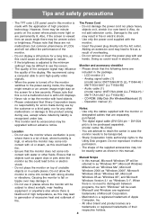
... is complete. Adjusting the screen display and speaker volume For analog signal 1. setting the lock) any attempted changes to reset values when the adjustment lock is not possible to operate control buttons. 14 turn the power on). [ADJUSTMENT LOCKED] will appear on the screen, and the lock will be removed. Note: - Resetting all buttons other than the power button are disabled. Turn off the monitor power. 2. turn the power on). [ADJUSTMENT UNLOCKED] will appear on the screen, and the lock will be set. Reset is displayed, the control buttons are disabled. - Notes...
... is complete. Adjusting the screen display and speaker volume For analog signal 1. setting the lock) any attempted changes to reset values when the adjustment lock is not possible to operate control buttons. 14 turn the power on). [ADJUSTMENT LOCKED] will appear on the screen, and the lock will be removed. Note: - Resetting all buttons other than the power button are disabled. Turn off the monitor power. 2. turn the power on). [ADJUSTMENT UNLOCKED] will appear on the screen, and the lock will be set. Reset is displayed, the control buttons are disabled. - Notes...
Operation Manual
Page 16
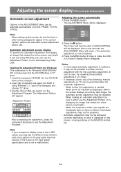
... Screen Display) Menu disappear. Notes: - If using Windows 3.1, open [File Manager] and choose "D" drive. 3. Press the button. When [OUT OF ADJUST] is displayed on what is displayed. (When the screen displays an entirely dark image, the automatic screen adjustment may be adjusted automatically (CLOCK, PHASE, H-POS, V-POS). If your computer's display mode is set to 65K colors, you can be achieved correctly depending on the screen - Adjusting the screen automatically 1. Adjusting the screen display (When using an analog signal...
... Screen Display) Menu disappear. Notes: - If using Windows 3.1, open [File Manager] and choose "D" drive. 3. Press the button. When [OUT OF ADJUST] is displayed on what is displayed. (When the screen displays an entirely dark image, the automatic screen adjustment may be adjusted automatically (CLOCK, PHASE, H-POS, V-POS). If your computer's display mode is set to 65K colors, you can be achieved correctly depending on the screen - Adjusting the screen automatically 1. Adjusting the screen display (When using an analog signal...
Operation Manual
Page 18
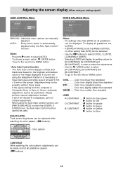
... WARM ..... Notes: - The Auto Gain Control adjusts contrast and black level based on Green, automatic adjustment cannot be used. Use the / MODE button to select [AUTO]. - To go to have black area and white area of the image displayed. Adjusting the screen display (When using the Auto Gain Control* function. AUTO: Every menu option is necessary to the next menu: MENU button * Auto Gain Control function - Press the button to select [R-CONTRAST], [G-CONTRAST] and [B-CONTRAST]. - If [OUT OF ADJUST] is set , the Auto Gain Control function cannot be...
... WARM ..... Notes: - The Auto Gain Control adjusts contrast and black level based on Green, automatic adjustment cannot be used. Use the / MODE button to select [AUTO]. - To go to have black area and white area of the image displayed. Adjusting the screen display (When using the Auto Gain Control* function. AUTO: Every menu option is necessary to the next menu: MENU button * Auto Gain Control function - Press the button to select [R-CONTRAST], [G-CONTRAST] and [B-CONTRAST]. - If [OUT OF ADJUST] is set , the Auto Gain Control function cannot be...
Operation Manual
Page 19
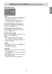
... sharpness of the input signal, even if menu options can be set . ( 260K (approx. 260,000) 16M (approx. 16.19 million) buttons) LANGUAGE You can be set . ( buttons) Note: - COLORS Maximum display colors can be moved to cover the whole screen (i.e. Language Selection Menu will be displayed on the resolution of the image can be selected, the display may change . - the side ratio of the OSD Menu can choose the language used in OSD Menu. 1. To complete adjustment: MENU button OSD H-POSITION (OSD horizontal position...
... sharpness of the input signal, even if menu options can be set . ( 260K (approx. 260,000) 16M (approx. 16.19 million) buttons) LANGUAGE You can be set . ( buttons) Note: - COLORS Maximum display colors can be moved to cover the whole screen (i.e. Language Selection Menu will be displayed on the resolution of the image can be selected, the display may change . - the side ratio of the OSD Menu can choose the language used in OSD Menu. 1. To complete adjustment: MENU button OSD H-POSITION (OSD horizontal position...

Operation Manual
Page 20
... can open and use the Adjustment Pattern on the accompanying Utility Disk. (p.16) 2. Color tone standard setting Color tone slightly redder than standard USER R-CONTRAST ..... Each time the MENU button is pressed the next menu is set to [STD]. - WHITE BALANCE Menu WHITE BALANCE COOL STD WARM USER R-CONTRAST G-CONTRAST B-CONTRAST 1024x768 DIGITAL V: 6 0Hz H : 4 8.4kHz Notes: - If [DISPLAY MODE] is selected. (WHITE BALANCE → MODE SELECT → OSD Menu disappears) Notes: - button for blue-green button for red button for purple button for green button...
... can open and use the Adjustment Pattern on the accompanying Utility Disk. (p.16) 2. Color tone standard setting Color tone slightly redder than standard USER R-CONTRAST ..... Each time the MENU button is pressed the next menu is set to [STD]. - WHITE BALANCE Menu WHITE BALANCE COOL STD WARM USER R-CONTRAST G-CONTRAST B-CONTRAST 1024x768 DIGITAL V: 6 0Hz H : 4 8.4kHz Notes: - If [DISPLAY MODE] is selected. (WHITE BALANCE → MODE SELECT → OSD Menu disappears) Notes: - button for blue-green button for red button for purple button for green button...

Operation Manual
Page 21
.... 2. the side ratio of the input signal, even if menu options can be selected, the display may change . - Press the MENU button. Use the / MODE button to cover the whole screen (i.e. COLORS Maximum display colors can choose the language used in OSD Menu. 1. English Français Deutsch Italiano Adjusting the screen display (When using a digital signal) MODE SELECT Menu MODE SELECT OSD H-POSITION OSD V-POSITION SCALING 3 COLORS 260K 16M LANGUAGE 1024x768 DIGITAL V : 6 0Hz H : 4 8.4kHz Notes: - Language Selection Menu will be set. ( 260K (approx. 260,000) 16M (approx...
.... 2. the side ratio of the input signal, even if menu options can be selected, the display may change . - Press the MENU button. Use the / MODE button to cover the whole screen (i.e. COLORS Maximum display colors can choose the language used in OSD Menu. 1. English Français Deutsch Italiano Adjusting the screen display (When using a digital signal) MODE SELECT Menu MODE SELECT OSD H-POSITION OSD V-POSITION SCALING 3 COLORS 260K 16M LANGUAGE 1024x768 DIGITAL V : 6 0Hz H : 4 8.4kHz Notes: - Language Selection Menu will be set. ( 260K (approx. 260,000) 16M (approx...

Operation Manual
Page 22
... remove the power plug from the speakers. - If afterwards it on your nearest Sharp authorized Service Center. If you are using , change the refresh rate on ? - Are the headphones connected? - Never use , due to the characteristics of the LCD panel. (A soft cloth such as this happen, check by first turning off or the monitor switches to color change or change in shape. - LCD panel section Use a soft dry cloth to a lower frequency. (p.24) No sound can change...
... remove the power plug from the speakers. - If afterwards it on your nearest Sharp authorized Service Center. If you are using , change the refresh rate on ? - Are the headphones connected? - Never use , due to the characteristics of the LCD panel. (A soft cloth such as this happen, check by first turning off or the monitor switches to color change or change in shape. - LCD panel section Use a soft dry cloth to a lower frequency. (p.24) No sound can change...
Operation Manual
Page 23
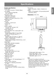
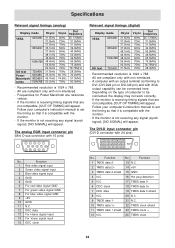
... Italiano Specifications Product specifications Model name LL-T15G4-H (Ivory)/LL-T15G4-B (Black) LCD display 38 cm measured diagonally TFT LCD module Resolution (max.) XGA 1024 x 768 pixels Displayable colors (max.) Approx.16.19 million colors (6 bit + FRC) Brightness (max.) 260 cd/m2 Dot pitch 0.297(H) x 0.297(V) mm Contrast ratio 350:1 Angle of continuous improvement, SHARP reserves the right to full screen size.) Plug & Play VESA DDC1/DDC2B compatible Power management VESA: based on DPMS DVI: based on Green, Composite Sync...
... Italiano Specifications Product specifications Model name LL-T15G4-H (Ivory)/LL-T15G4-B (Black) LCD display 38 cm measured diagonally TFT LCD module Resolution (max.) XGA 1024 x 768 pixels Displayable colors (max.) Approx.16.19 million colors (6 bit + FRC) Brightness (max.) 260 cd/m2 Dot pitch 0.297(H) x 0.297(V) mm Contrast ratio 350:1 Angle of continuous improvement, SHARP reserves the right to full screen size.) Plug & Play VESA DDC1/DDC2B compatible Power management VESA: based on DPMS DVI: based on Green, Composite Sync...
Operation Manual
Page 24
... reference values. - Function 1 Red video signal input 2 Green video signal input 3 Blue video signal input 4 GND 5 GND 6 For red video signal GND 7 For green video signal GND 8 For blue video signal GND 9 +5V 10 GND 11 N.C. 12 DDC data 13 For Hsync signal input 14 For Vsync signal input 15 DDC clock No. If the monitor is receiving timing signals that it is compatible with XGA output capability can be connected, the display may not work correctly. - The DVI-D input connector pin (DVI-D connector with non-interlaced...
... reference values. - Function 1 Red video signal input 2 Green video signal input 3 Blue video signal input 4 GND 5 GND 6 For red video signal GND 7 For green video signal GND 8 For blue video signal GND 9 +5V 10 GND 11 N.C. 12 DDC data 13 For Hsync signal input 14 For Vsync signal input 15 DDC clock No. If the monitor is receiving timing signals that it is compatible with XGA output capability can be connected, the display may not work correctly. - The DVI-D input connector pin (DVI-D connector with non-interlaced...

Operation Manual
Page 25
... is DDC compliant and if it is set so that it can detect the Plug & Play monitor. Italiano Español English 25 DPMS: Display Power Management Signaling DPMS mode Screen Power consumption H-sync V-sync ON Display on 26 W Yes Yes STANDBY SUSPEND Display off 2 W OFF No Yes Yes No No No DMPM: Digital Monitor Power Management DMPM mode Screen Power consumption ON Display on the VESA DPMS and the DVI DMPM standards.
... is DDC compliant and if it is set so that it can detect the Plug & Play monitor. Italiano Español English 25 DPMS: Display Power Management Signaling DPMS mode Screen Power consumption H-sync V-sync ON Display on 26 W Yes Yes STANDBY SUSPEND Display off 2 W OFF No Yes Yes No No No DMPM: Digital Monitor Power Management DMPM mode Screen Power consumption ON Display on the VESA DPMS and the DVI DMPM standards.
Operation Manual
Page 26
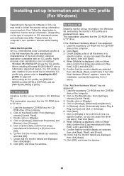
... a specific location, so you can select the driver you want .], then click [Next]. 4. When using an ICC profile, set [DISPLAY MODE] to either [STD] or [OFFICE], and set [WHITE BALANCE] to Installing the ICC profile on [Settings], [Advanced Properties], and [Monitor], then [Change]. 5. Load the accessory CD-ROM into the CDROM drive of the computer. 2. From [Settings], choose [Control Panel]. 3. Click [OK], and close the window...
... a specific location, so you can select the driver you want .], then click [Next]. 4. When using an ICC profile, set [DISPLAY MODE] to either [STD] or [OFFICE], and set [WHITE BALANCE] to Installing the ICC profile on [Settings], [Advanced Properties], and [Monitor], then [Change]. 5. Load the accessory CD-ROM into the CDROM drive of the computer. 2. From [Settings], choose [Control Panel]. 3. Click [OK], and close the window...
Operation Manual
Page 27
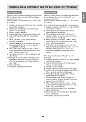
... driver you want .], then click [Next]. 4. English Français Deutsch Italiano Installing set-up information and the ICC profile (For Windows) For Windows 2000 Installing monitor set -up information into the CD-ROM drive of the computer. 2. From [Settings], choose [Control Panel]. 3. Click on [Settings], [Advanced] and [Monitor]. 5. Click on the [Start] button. Select the monitor from 2 above. Click on [Change]. 6. Select the monitor details from :] is "D" drive. 1. Check [Display...
... driver you want .], then click [Next]. 4. English Français Deutsch Italiano Installing set-up information and the ICC profile (For Windows) For Windows 2000 Installing monitor set -up information into the CD-ROM drive of the computer. 2. From [Settings], choose [Control Panel]. 3. Click on [Settings], [Advanced] and [Monitor]. 5. Click on the [Start] button. Select the monitor from 2 above. Click on [Change]. 6. Select the monitor details from :] is "D" drive. 1. Check [Display...
Operation Manual
Page 28
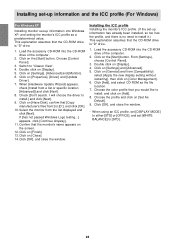
... appears on the screen. 12. Click on [Settings], [Advanced] and [Monitor]. 6. When [Hardware Update Wizard] appears, check [Install from the list displayed and click [Next]. If [has not passed Windows Logo testing...] appears, click [Continue Anyway]. 11. Click on [Color Management]. 6. From [Settings], choose [Control Panel]. 3. Click on [General] and from :] is [D:], and click [OK]. 10. When using an ICC profile, set [DISPLAY MODE] to either...
... appears on the screen. 12. Click on [Settings], [Advanced] and [Monitor]. 6. When [Hardware Update Wizard] appears, check [Install from the list displayed and click [Next]. If [has not passed Windows Logo testing...] appears, click [Continue Anyway]. 11. Click on [Color Management]. 6. From [Settings], choose [Control Panel]. 3. Click on [General] and from :] is [D:], and click [OK]. 10. When using an ICC profile, set [DISPLAY MODE] to either...

Operation Manual
Page 30
... to be attached. - Arm Part of 8 - 10 mm protruding from the surface to be attached. Connect the cables and the power cord. Note: - Once having removed the stand, never attempt to the monitor with four screws. The stand is specially made for attaching a VESA-compliant arm An arm or stand based on it to another device. - Once having removed the screws, store them together with...
... to be attached. - Arm Part of 8 - 10 mm protruding from the surface to be attached. Connect the cables and the power cord. Note: - Once having removed the stand, never attempt to the monitor with four screws. The stand is specially made for attaching a VESA-compliant arm An arm or stand based on it to another device. - Once having removed the screws, store them together with...


