Service Manual
Page 2
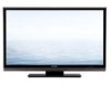
... list LC-C4655U (No. S78N2LC42D65U) Service Manual. Description PRINTED WIRING BOARD ASSEMBLIES R/C, LED Unit KEY Unit MAIN Unit POWER Unit LC-42D65U (No. R1LK460D3LW60Z VHPGPFSV51M-1 VHIS24CS02JBES VHIS24CS02JDES VHIS24CS02JCES VHIS24CS02JFES VHIS24CS02JEES VRS-CZ1JF470JY VRS-CZ1JF470JY Note Some parts changed some parts. MAIN Unit ... to a Parts list PACKING PARTS AND ACCESSORIES Please refer to the LC-42D65U (No. Delete Add Change Change Change Change Change Change Change Change i LC-C4655U LOCU-C4T6L55IUNE AND DIFFERENCES FROM BASE MSOerDvEicLe Manual OUTLINE This model is ...
... list LC-C4655U (No. S78N2LC42D65U) Service Manual. Description PRINTED WIRING BOARD ASSEMBLIES R/C, LED Unit KEY Unit MAIN Unit POWER Unit LC-42D65U (No. R1LK460D3LW60Z VHPGPFSV51M-1 VHIS24CS02JBES VHIS24CS02JDES VHIS24CS02JCES VHIS24CS02JFES VHIS24CS02JEES VRS-CZ1JF470JY VRS-CZ1JF470JY Note Some parts changed some parts. MAIN Unit ... to a Parts list PACKING PARTS AND ACCESSORIES Please refer to the LC-42D65U (No. Delete Add Change Change Change Change Change Change Change Change i LC-C4655U LOCU-C4T6L55IUNE AND DIFFERENCES FROM BASE MSOerDvEicLe Manual OUTLINE This model is ...
Service Manual
Page 20
... the factory before shipping. Plug in the AC cord with a USB port. • The file system of Main Board terminals, under INPUT3 terminal. 3. MAIN Unit: DUNTKE716FM01 2. Follow the steps below appears within 20-40 seconds. Now the USB Memory for version upgrade.... following. • When replacing the following units, make an adjustment according to upgrade the software 1. Unplug the AC cord. 2. LC-C4655U LCC-HC4A655PUTER 5. Software version upgrade The model employs the following procedure. 1. ADJUSTMENT Service Manual [1] ADJUSTMENT PROCEDURE The adjustment values are ...
... the factory before shipping. Plug in the AC cord with a USB port. • The file system of Main Board terminals, under INPUT3 terminal. 3. MAIN Unit: DUNTKE716FM01 2. Follow the steps below appears within 20-40 seconds. Now the USB Memory for version upgrade.... following. • When replacing the following units, make an adjustment according to upgrade the software 1. Unplug the AC cord. 2. LC-C4655U LCC-HC4A655PUTER 5. Software version upgrade The model employs the following procedure. 1. ADJUSTMENT Service Manual [1] ADJUSTMENT PROCEDURE The adjustment values are ...

Service Manual
Page 22
...screen will be shown during a minor upgrade. NOTE: When you are done with power button pressed down. 4. Plug in the "Main software version upgrade". After the unit startup, the upgrade starts. Unplug the AC cord and remove the USB Memory for monitor microprocessor ...upgrade is ongoing, never power off the unit. Up on completion of Main Board terminals, under INPUT3 terminal. 3. After 5 seconds, unpress the power button. Also, the upgrade failure screen will be the cause. 7. LC-C4655U 2.3. The power led will stop blinking. UPGRADE SUCCESS SDB655 8. itor ...
...screen will be shown during a minor upgrade. NOTE: When you are done with power button pressed down. 4. Plug in the "Main software version upgrade". After the unit startup, the upgrade starts. Unplug the AC cord and remove the USB Memory for monitor microprocessor ...upgrade is ongoing, never power off the unit. Up on completion of Main Board terminals, under INPUT3 terminal. 3. After 5 seconds, unpress the power button. Also, the upgrade failure screen will be the cause. 7. LC-C4655U 2.3. The power led will stop blinking. UPGRADE SUCCESS SDB655 8. itor ...

Service Manual
Page 23
SDB655 5. Upon completion of Main Board terminals, under INPUT3 terminal. 3. Plug in the process will trigger the upgrade failure screen. UPGRADE FAILURE SDB655 6. Unplug the AC cord and remove the USB Memory for version upgrade (prepared as explained in the "Main software version upgrade". Now the software ... After the unit startup, the system upgrade screen as shown below appears within 20-40 seconds. UPGRADE SUCCESS SDB6555 7. LC-C4655U 2.4. Unplug the AC cord. 2. Copy the file LAKELAxx.USB and LAKELDxx.LCD to USB memory. 2.4.1 How to upgrade the software 1.
SDB655 5. Upon completion of Main Board terminals, under INPUT3 terminal. 3. Plug in the process will trigger the upgrade failure screen. UPGRADE FAILURE SDB655 6. Unplug the AC cord and remove the USB Memory for version upgrade (prepared as explained in the "Main software version upgrade". Now the software ... After the unit startup, the system upgrade screen as shown below appears within 20-40 seconds. UPGRADE SUCCESS SDB6555 7. LC-C4655U 2.4. Unplug the AC cord. 2. Copy the file LAKELAxx.USB and LAKELDxx.LCD to USB memory. 2.4.1 How to upgrade the software 1.
Service Manual
Page 41
... are subject to replace these parts with " " are arranged in alphabetical order. MODEL CONTENTS LC-C4655U [1] PRINTED WIRING BOARD ASSEMBLIES [2] LCD PANEL (NOTE: THE PARTS HERE SHOWN ARE SUPPLIED AS AN ASSEMBLY BUT NOT INDEPENDENTLY.) [3] DUNTKE264FM02 (R/C, LED Unit) [4] DUNTKE716FM01 (MAIN Unit) [5] CABINET AND MECHANICAL PARTS [6] SUPPLIED ACCESSORIES [7] PACKING PARTS (NOT REPLACEMENT ITEM) [8] SERVICE... service only. Be sure to change without notice. This document has been published to be used for maintaining the safety of the set . PartsGuide LC-C4655U PARTS GUIDE No.
... are subject to replace these parts with " " are arranged in alphabetical order. MODEL CONTENTS LC-C4655U [1] PRINTED WIRING BOARD ASSEMBLIES [2] LCD PANEL (NOTE: THE PARTS HERE SHOWN ARE SUPPLIED AS AN ASSEMBLY BUT NOT INDEPENDENTLY.) [3] DUNTKE264FM02 (R/C, LED Unit) [4] DUNTKE716FM01 (MAIN Unit) [5] CABINET AND MECHANICAL PARTS [6] SUPPLIED ACCESSORIES [7] PACKING PARTS (NOT REPLACEMENT ITEM) [8] SERVICE... service only. Be sure to change without notice. This document has been published to be used for maintaining the safety of the set . PartsGuide LC-C4655U PARTS GUIDE No.

Service Manual
Page 42
... CODE PRICE NEW PART RANK MARK DELIVERY DESCRIPTION [1] PRINTED WIRING BOARD ASSEMBLIES N DUNTKE264FM02 AP N DUNTKE266FM02 AG N DUNTKE716FM01 CC N RDENCA295WJQZ BR X R/C, LED Unit X KEY Unit X MAIN Unit X POWER Unit [2] LCD PANEL (NOTE: THE PARTS... VRS-CJ1JF103JY AA R124 VRS-CJ1JF103JY AA R135 VRS-CY1JF000JY AA RMC101 RRMCUA053WJZZ AE SLD101 PSLDPA076WJFW AD [4] DUNTKE716FM01 (MAIN Unit) J Capacitor, 2.2 16V Ceramic J Capacitor, 10 16V Electrolytic J Capacitor, 0.01 50V Ceramic J ... J Resistor, 47 1/16W Metal Oxide J Resistor, 47 1/16W Metal Oxide 2 LC-C4655U NO.
... CODE PRICE NEW PART RANK MARK DELIVERY DESCRIPTION [1] PRINTED WIRING BOARD ASSEMBLIES N DUNTKE264FM02 AP N DUNTKE266FM02 AG N DUNTKE716FM01 CC N RDENCA295WJQZ BR X R/C, LED Unit X KEY Unit X MAIN Unit X POWER Unit [2] LCD PANEL (NOTE: THE PARTS... VRS-CJ1JF103JY AA R124 VRS-CJ1JF103JY AA R135 VRS-CY1JF000JY AA RMC101 RRMCUA053WJZZ AE SLD101 PSLDPA076WJFW AD [4] DUNTKE716FM01 (MAIN Unit) J Capacitor, 2.2 16V Ceramic J Capacitor, 10 16V Electrolytic J Capacitor, 0.01 50V Ceramic J ... J Resistor, 47 1/16W Metal Oxide J Resistor, 47 1/16W Metal Oxide 2 LC-C4655U NO.


