Service Manual
Page 1
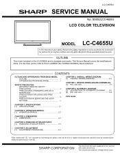
...FREE SOLDER iv PRECAUTIONS IN SERVICING THE HDCPKEY ROM v CHAPTER 6. SCHEMATIC DIAGRAM [1] DESCRIPTION OF SCHEMATIC DIAGRAM .........8-1 [2] R/C, LED Unit 8-2 Parts Guide CHAPTER 1. DIMENSIONS [1] DIMENSIONS 3-1 CHAPTER 4. PRINTED WIRING BOARD ASSEMBLIES [1] R/C, LED Unit 7-1 CHAPTER 8. This document has been published to those specified should be used . OPERATION MANUAL [1] OPERATION MANUAL 2-1 CHAPTER 3. TopPage LC-C4655U SERVICE MANUAL... by safety regulations in some parts. S08S2LCC4655U LCD COLOR TELEVISION MODEL LC-C4655U In the interests of the set.
...FREE SOLDER iv PRECAUTIONS IN SERVICING THE HDCPKEY ROM v CHAPTER 6. SCHEMATIC DIAGRAM [1] DESCRIPTION OF SCHEMATIC DIAGRAM .........8-1 [2] R/C, LED Unit 8-2 Parts Guide CHAPTER 1. DIMENSIONS [1] DIMENSIONS 3-1 CHAPTER 4. PRINTED WIRING BOARD ASSEMBLIES [1] R/C, LED Unit 7-1 CHAPTER 8. This document has been published to those specified should be used . OPERATION MANUAL [1] OPERATION MANUAL 2-1 CHAPTER 3. TopPage LC-C4655U SERVICE MANUAL... by safety regulations in some parts. S08S2LCC4655U LCD COLOR TELEVISION MODEL LC-C4655U In the interests of the set.
Service Manual
Page 5
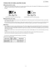
... with polarity indication on the PWB silk. The LF symbol indicates lead-free solder, and is blackened during use a dedicated soldering bit, if you confirm the steady soldering condition. PRECAUTIONS FOR USING LEAD-FREE SOLDER LC-C4655U „Employing lead-free solder • "PWBs" of the soldering bit is attached on the PWBs and service manuals.
... with polarity indication on the PWB silk. The LF symbol indicates lead-free solder, and is blackened during use a dedicated soldering bit, if you confirm the steady soldering condition. PRECAUTIONS FOR USING LEAD-FREE SOLDER LC-C4655U „Employing lead-free solder • "PWBs" of the soldering bit is attached on the PWBs and service manuals.


