Sharp LC-26SH12U Support Question
Sharp LC-26SH12U Support Question
Find answers below for this question about Sharp LC-26SH12U - 26" LCD HDTV.Need a Sharp LC-26SH12U manual? We have 1 online manual for this item!
Question posted by tom1ridley on October 15th, 2022
Owners Manual
Where Can I Get A Owners Manual For The Lc-26sh12u
Current Answers
Answer #1: Posted by HelpHero on October 15th, 2022 8:29 PM
HelpHero

Member since:
September 3rd, 2022 Points: 523,390

Member since:
September 3rd, 2022 Points: 523,390
Get the manual here.
https://www.manualslib.com/products/Sharp-Lc-26sh12u-26-Lcd-Hdtv-2784825.html
I hope this is helpful? PLEASE "ACCEPT" and mark it "HELPFUL" to complement my little effort. Hope to bring you more detailed answers.
Helphero
Answer #2: Posted by SonuKumar on October 15th, 2022 10:22 PM
SonuKumar

Member since:
May 9th, 2021 Points: 16,619,310
Member since:
May 9th, 2021 Points: 16,619,310
Please respond to my effort to provide you with the best possible solution by using the "Acceptable Solution" and/or the "Helpful" buttons when the answer has proven to be helpful.
Regards,
Sonu
Your search handyman for all e-support needs!!
Related Sharp LC-26SH12U Manual Pages
Service Manual - Page 1

... ...I-1, I-2 • MECHANICAL EXPLODED VIEWS J-1~J-3 • REPLACEMENT PARTS LIST K1-1~K2-9
This document has been published to be used for after sales service only. S3701LC26SH12
LCD COLOR TELEVISION
MODEL LC-26SH12U
In the interests of user-safety (Required by safety regulations in some countries) the set should be restored to its original condition and only...
Service Manual - Page 2

... original positions.
6. USE THE DESIGNATED PARTS
The parts in the operation manual.
2. BE CAREFUL WITH THE LCD PANEL
Avoid a shock to the IC and Transistor). Take enough care to...the VERSION LETTER.) 1. PERFORM A SAFETY CHECK AFTER SERVICING
Confirm that these parts in your SERVICE MANUAL. Check the insulation between the cord plug
terminals and the eternal exposure metal [Note 2] should...
Service Manual - Page 4

...No
No
-- Min
Sec
A2-1 GENERAL SPECIFICATIONS
G-1 TV System
G-2 Tuning System
G-3 Signal
LCD
Color System Speaker
Sound Output Broadcasting System Tuner and Receive CH Intermediate Digital Frequency Analog
Preset ...CH Stereo/Dual TV Sound Tuner Sound Muting Video Signal
LCD Size / Visual Size LCD Type Number of Pixels
View Range
Position Size Impedance Max 10%(Typical) ...
Service Manual - Page 7

...;480p (4:3)
720×480p (16:9)
720×576i (4:3)
720×576i (16:9)
720×576p (4:3)
720×576p (16:9)
1280×720p
1920×1080i
Owner's Manual
Language
w/Guarantee Card
Remote Control Unit
Rod Antenna
Poles
Terminal
Loop Antenna
Terminal
U/V Mixer
DC Car Cord (Center+)
Guarantee Card
Warning Sheet
Circuit Diagram
Antenna...
Service Manual - Page 9

...Refer to Fig. 1-4)
1. Disconnect the following connectors: (CP406, CP1001 and CP2407).
2. Remove the LCD Block in the direction of arrow (B). 7. Remove the Plate Button Ass'y in the direction of arrow... direction of arrow.
11
Remocon PCB
1 1 1
1
1 1 1 Back Cabinet
Fig. 1-3
1-4: LCD BLOCK (Refer to Fig. 1-3) 1. REMOVAL OF MECHANICAL PARTS AND P.C. Remove the 4 screws 3. 8.
...
Service Manual - Page 10

...1. Remove the 9 screws 4. 7. Remove the Digital PCB and Shield Digital in the direction of arrow (B).
1 2 3 2
4 4
Shield Digital
1-7: COVER LCD (Refer to Fig. 1-5)
1. Remove the Cover LCD in the
direction of arrow.
1 1
1 1
Cover LCD
LCD Panel
(A) Plate Jack
(B)
Digital PCB
Fig. 1-7
Fig. 1-5
1-6: POWER PCB (Refer to Fig. 1-6)
1. Disconnect the following connector: (CP3401...
Service Manual - Page 14
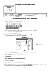
...After the Up-Date, the screen will now have the correct DATA for more than 2 seconds. APJG176121
Parts Name
2007 USA DTV LCD ROM DISC
Remarks Up-Date of the USB connector cover, remove the USB connector cover. Insert the AC CORD of the set and... to the initializing of WINDOWS2000 is used . The computer of shipping. 9. SERVICING FIXTURES AND TOOLS
JG176 2007 USA DTV LCD ROM DISC
Ref.
Service Manual - Page 15
...
button (8) on the POWER. 11.
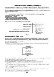
Please refer to the TV mode. 2. MICON Version Digital TV MICON Fimware
HCS CHK SUM : 07EA HRM CHK SUM : 9BD4 LCD PWR ON : 0000 OEC6088A_T039 DTV CA03B72232
FIG. 1
Initial setting data check sum. WHEN REPLACING EEPROM (MEMORY) IC
CONFIRMATION OF CHECK SUM, POWER ON TOTAL HOURS...
Service Manual - Page 16

... the INPUT button on the remote control until the contrast step No. FUNCTION 23 BAK LIGHT CENT 24 BAK LIGHT MAX 25 BAK LIGHT MIN 26 BRIGHT CENT 27 BRIGHT MAX 28 BRIGHT MIN 29 TINT 30 SHARP CENT 31 SHARP MAX 32 SHARP MIN 33 CONTRAST CENT 34 CONTRAST MAX...
Service Manual - Page 17

... Aging Test for more than 15 minutes. 2. Check if the picture is normal. 6. Activate the adjustment mode display of Fig. 2-1 and
press the channel button (26) on the remote control to select "BRIGHT CENT". 6. Activate the adjustment mode display of Fig. 1-1 and
press the channel button (03) on the remote control...
Service Manual - Page 19

... B DRIVEʢWʣ 20 B CUTOFFʢWʣ 21 H POSI 60
22 V POSI 60
23 BAK LIGHT CENT
24 BAK LIGHT MAX
25 BAK LIGHT MIN
26 BRIGHT CENT
27 BRIGHT MAX
28 BRIGHT MIN
29 TINT
30 SHARP CENTER
31 SHARP MAX
32 SHARP MIN
33 CONT CENTER
34 CONT MAX...
Service Manual - Page 21
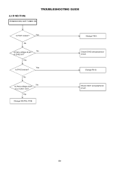
Check IC402 and peripheral circuit.
Check IC401 and peripheral circuit. E-1 TROUBLESHOOTING GUIDE
(LCD SECTION)
POWER DOES NOT TUNER ON
Is F401 broken? No
No Is there voltage at pin 1 No of IC401 19V?
Change R412.
Change F401.
Yes
Change DIGITAL PCB. Yes
No
Is there voltage at pin 10 of IC402 6V? Yes
Yes Is R412 broken?
Service Manual - Page 26
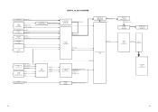
... IC IC1002
NJW1173V(TE1)
TONE AUDIO L/R
SOUND AMP IC IC1001
AN17808B
AMP L/R
SPEAKER L/R SP1001, SP1002
S0412F03
LVDS IC IC2405 ICSV385AGLFT
Tx OUT
CP2407 20389-Y30E
LCD PANEL V2301
LK255T3LZ5AZ
F-1
F-2
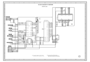
Service Manual - Page 27

...CP3401
1 SOUND +B 2
3 4
SOUND GND
5
6
GND
7
8 SW +12V 9
10 LCD+B
11 POWR_ON_H
12 LIGHTE_CTL
13 INVERTER_H
14
AT +5V
15
16 POWER FAIL
17
18
GND
19
...SW +1.5V 23
REG+9V IC3404 P.CON +9V BA00BC0WFP
SOUND AMP IC1001
AN17808B
AV SW IC701 AN15853B-E1
Q3410 LCD +B RSQ035P03
PANEL V2301 LK255T3LZ5A
Q3406 P.CON +5V 2SB1132
AD CONVERTER IC6601
MST3583M-LF-110
SUBɹMICON IC101
...
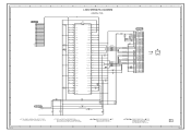
Service Manual - Page 35
... NFIO1 NFIO0
C2503 0.1 B
7
48 47 46 45 44 43 42 41 40 39 38 37 36 35 34 33 32 31 30 29 28 27 26 25
HY27US08281A-TP
FLASH MEMORY IC
FOR FIRM UPDATE
CP2401 YKF45-0036N
1
+5V
2
USBN
3
USBP
6
4
GND
JG2412 JG2413 JG2414
R2422 15K R2423 15K
FROM/TO...
Service Manual - Page 38

...+-1%
4 SOUND GND
5.0
6
5
GND
6
GND
7
GND
8
SW+12V
9
SW+12V
10
LCD+B
11 SYS_POWER_H
12 LIGHT_POWER_H
13 INVETER_H
14
AT+5V
S801X
B3407 HCB3216KF-391T20
B3403 FCM1608KF-102T02 B3404 FCM1608KF-... 0.22 B
5.0
0 SW Q3408 KRC102SRTK S802Y
4.7
4.7 4.7
4
5
6
S
D
D
LCD+B POWER_ON-H
LCD+B
LCD+B_SW IC Q3410
RSQ035P03
R3438 10K
15
AT+5V
16 POWER FAIL
5
17
GND
18
GND
19...
Service Manual - Page 39
...G
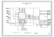
LVDS SHEMATIC DIAGRAM
(DIGITAL PCB)
C2591 0.1 B
C2593 0.1 B C2592 6.3V 220
V-S
C2594 0.1 B
3.3 Vcc
1
28 27 26 25 24 23 22 21 20 19 18 17 16 15 14 13 12 11 10 9
R7
2
3.3 TxIN5
R5
3
3.3 TxIN6
...220
V-S
B2502 FCM1608KF-151T06
R2507 180
B2503
FCM1608KF-151T06
B2504
FCM1608KF-151T06
CD7201 CHRU1301
LCD PANEL
V2301 LK255T3LZ5AZ
C2595 6.3V 220 V-S
NOTE:THE DC VOLTAGE AT EACH PART ...
Service Manual - Page 40
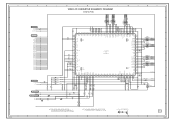
...
NC
NC
GND
VSYNC
HSYNC
VREFN
0.7
3.3
B6602
VDDC AVDD_PLL
1 2 3 4 5 6 7 8 9 10 11 12 13 14 15 16 17 18 19 20 21 22 23 24 25 26 27 28 29 30 31 32 33 34 35 36 37 38
1.0 2.5 2.5 3.3 0 0.7
0 1.3 1.0
0 0.7
00000000000000000 NC NC NC NC NC NC NC NC NC NC NC NC...
Service Manual - Page 41
...TO FLASH
TX_[X242]
RX_[X242]
FROM/TO FRONT END AFT_1 AFT_2 SD-H AFT
5
FROM/TO POWER3
DTV_ON-H LIGHT_CTL
LCD-H INVETER_H POWER_ON-H POWER_FAIL
P.CON+5V
4
FROM/TO SOUND
POWER_ON_MUTE_H
5.0 LCD_ON
5.0 LCD_H
5.0 NC NC
0 NC NC...NC
0 REMOCON_IN
5.0
LED-H DTV_ON-H POWER_ON-H
C102 0.01 B
R104
100
33 32 31 30 29 28 27 26 25 24 23
44 43 42 41 40 39 38 37 36 35 34
5.0
VAREF
NC
NC
0
5.0
...
Service Manual - Page 49

...GND
7
7
GND
GND
7
SW+12V 8
8
SW+12V
GND
8
7
SW+12V 9
9
SW+12V
GND
9
LCD+B
10
10
LCD+B
GND
10
POWER_ON_H 11
11 POWER_ON_H
Analog/Dimming 11
LIGHTE_CTL 12
12 LIGHTE_CTL
ON/OFF
12
INVETER_H 13
13 INVETER_H
PWM/Dimming ... LA NOMENCLATURE DES PIECES
C
D
TO LCD PANEL CD7201
LCD PANEL V2301
E
21
GND
22
NC
23
GND
24
GND
25
GND
26
GND
27
GND
28 VDD+5V
29 ...
Similar Questions


Manual Setup For Television Model 13lm100b
Set up without remote control?
Set up without remote control?
(Posted by Choco8me2 10 years ago)


Manual For Sharp Lc26sh12u Lcd Tv
We had the TV mounted on the wall, but now want to stand it up and my husband misplaced the stand. I...
We had the TV mounted on the wall, but now want to stand it up and my husband misplaced the stand. I...
(Posted by dooleytree 13 years ago)
My Sharp Lc-26sh12u Will Not Work Through My Stero System On Channel 60.
I have hooked up my sharp T.v. to my Philips stero system through both the digital input and regular...
I have hooked up my sharp T.v. to my Philips stero system through both the digital input and regular...
(Posted by sailrv88 13 years ago)