
Service Manual
Page 1
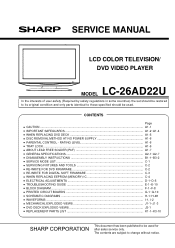
... FOR DIGITAL SOFT FIRMWARE C-3 • WHEN REPLACING EEPROM (MEMORY) IC C-4 • ELECTRICAL ADJUSTMENTS D-1~D-5 • TROUBLESHOOTING GUIDE E-1~E-10 • BLOCK DIAGRAM ...F-1~F-8 • PRINTED CIRCUIT BOARDS G-1~G-10 • SCHEMATIC DIAGRAMS ...H-1~H-48 • WAVEFORMS ...I-1, I-2 • MECHANICAL EXPLODED VIEWS J1-1~J1-3 • DVD DECK EXPLODED VIEWS J2-1 • REPLACEMENT PARTS LIST K1-1~K3-10 This document has been published to be used for after sales service only. LCD COLOR TELEVISION/ DVD VIDEO PLAYER MODEL LC-26AD22U In the interests of user...
... FOR DIGITAL SOFT FIRMWARE C-3 • WHEN REPLACING EEPROM (MEMORY) IC C-4 • ELECTRICAL ADJUSTMENTS D-1~D-5 • TROUBLESHOOTING GUIDE E-1~E-10 • BLOCK DIAGRAM ...F-1~F-8 • PRINTED CIRCUIT BOARDS G-1~G-10 • SCHEMATIC DIAGRAMS ...H-1~H-48 • WAVEFORMS ...I-1, I-2 • MECHANICAL EXPLODED VIEWS J1-1~J1-3 • DVD DECK EXPLODED VIEWS J2-1 • REPLACEMENT PARTS LIST K1-1~K3-10 This document has been published to be used for after sales service only. LCD COLOR TELEVISION/ DVD VIDEO PLAYER MODEL LC-26AD22U In the interests of user...

Service Manual
Page 3
... or when unused for replacement of time. 14) Refer all instructions. 5) Do not use attachments/accessories specified by the manufacturer. 12) Use only with the cart, stand, tripod, bracket, or table specified by the manufacturer, or sold with the manufacturer's instructions. 8) Do not install near water. 6) Clean only with one wider than the other electric light or power circuits, or where it...
... or when unused for replacement of time. 14) Refer all instructions. 5) Do not use attachments/accessories specified by the manufacturer. 12) Use only with the cart, stand, tripod, bracket, or table specified by the manufacturer, or sold with the manufacturer's instructions. 8) Do not install near water. 6) Clean only with one wider than the other electric light or power circuits, or where it...
Service Manual
Page 4
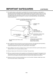
... the minimum level before you turn off the power and unplug all of the equipment from the wall outlet. Otherwise, sudden high volume sound may cause an electric shock and serious personal injury. IMPORTANT SAFEGUARDS (CONTINUED) 19) If an outside antenna or cable system is connected to the unit, be sure the service technician uses replacement parts specified by the manufacturer or...
... the minimum level before you turn off the power and unplug all of the equipment from the wall outlet. Otherwise, sudden high volume sound may cause an electric shock and serious personal injury. IMPORTANT SAFEGUARDS (CONTINUED) 19) If an outside antenna or cable system is connected to the unit, be sure the service technician uses replacement parts specified by the manufacturer or...
Service Manual
Page 5
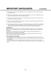
... the room rises suddenly. If the liquid gets in the panel. In such cases, change the location of time. IMPORTANT SAFEGUARDS (CONTINUED) 25) Do not allow the product to the point of cable entry as practical. CONDENSATION Moisture will be connected to the grounding system of the building, as close to output distorted sound for at a moderate level. A1-4
... the room rises suddenly. If the liquid gets in the panel. In such cases, change the location of time. IMPORTANT SAFEGUARDS (CONTINUED) 25) Do not allow the product to the point of cable entry as practical. CONDENSATION Moisture will be connected to the grounding system of the building, as close to output distorted sound for at a moderate level. A1-4
Service Manual
Page 6
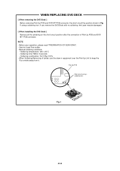
... with no soldering, the Laser may be damaged. [ When installing the DVD Deck ] Remove all the soldering on the short circuit position after the connection of solder, use the draw in Fig. 1 using a soldering iron. NOTE • Before your operation, please read "PREPARATION OF SERVICING". • Use the Lead Free solder. • Manual soldering conditions • Soldering temperature: 320 ± 20...
... with no soldering, the Laser may be damaged. [ When installing the DVD Deck ] Remove all the soldering on the short circuit position after the connection of solder, use the draw in Fig. 1 using a soldering iron. NOTE • Before your operation, please read "PREPARATION OF SERVICING". • Use the Lead Free solder. • Manual soldering conditions • Soldering temperature: 320 ± 20...
Service Manual
Page 7
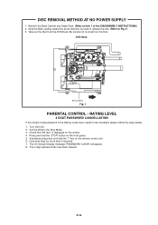
... Level menu needs to scratch on the remote control unit. 6. The 4 digit password has now been cleared. DVD Deck Belt Loading Fig. 1 PARENTAL CONTROL - Take out the Disc from the DVD Deck. Turn Unit ON. 2. Check that 'No disc' is displayed on the front panel. 5. Press and hold the '7' key on the Disc. Simultaneously press and hold the 'STOP' button on the screen. 4. A1-6 Set the DVD...
... Level menu needs to scratch on the remote control unit. 6. The 4 digit password has now been cleared. DVD Deck Belt Loading Fig. 1 PARENTAL CONTROL - Take out the Disc from the DVD Deck. Turn Unit ON. 2. Check that 'No disc' is displayed on the front panel. 5. Press and hold the '7' key on the Disc. Simultaneously press and hold the 'STOP' button on the screen. 4. A1-6 Set the DVD...
Service Manual
Page 9
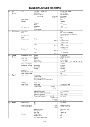
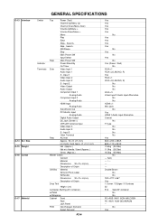
... G-4 Signal Slow speed Broadcasting System Tuner and Receive CH Intermediate Digital Frequency Analog Preset CH Stereo/Dual TV Sound Tuner Sound Muting Video Signal Fwd Rev Analog Digital System Destination CH Coverage Picture(FP) Sound(FS) FP-FS Input Level Output Level S/N Ratio (Weighted) Horizontal Resolution at DVD Mode Actual Actual RGB Signal Audio Signal Output Level Input Level Output Level at DVD at TV G-5 Power Power Source Power Consumption Protector Digital Output Level S/N Ratio at DVD (Weighted) Harmonic Distortion Frequency Response : at DVD at Video CD...
... G-4 Signal Slow speed Broadcasting System Tuner and Receive CH Intermediate Digital Frequency Analog Preset CH Stereo/Dual TV Sound Tuner Sound Muting Video Signal Fwd Rev Analog Digital System Destination CH Coverage Picture(FP) Sound(FS) FP-FS Input Level Output Level S/N Ratio (Weighted) Horizontal Resolution at DVD Mode Actual Actual RGB Signal Audio Signal Output Level Input Level Output Level at DVD at TV G-5 Power Power Source Power Consumption Protector Digital Output Level S/N Ratio at DVD (Weighted) Harmonic Distortion Frequency Response : at DVD at Video CD...
Service Manual
Page 10
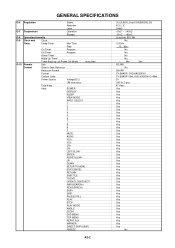
... No A2-2 ENTER RIGHT/SLOW+ UP DOWN SETUP/TV MENU EXIT/CANCEL RETURN SUBTITLE TV/DVD OPEN/CLOSE(EJECT) FWD(SEARCH+) REV(SEARCH-) SKIP+ SKIP- GENERAL SPECIFICATIONS G-6 G-7 G-8 G-9 G-10 Regulation Safety Radiation Laser Temperature Operation Storage Operating Humidity Clock and Clock Timer Sleep Timer Max Time Step On Timer Program Off Timer Program Game Timer Wake Up Timer Timer Back-up (at Power Off Mode) more than 80% RH No 120 Min...
... No A2-2 ENTER RIGHT/SLOW+ UP DOWN SETUP/TV MENU EXIT/CANCEL RETURN SUBTITLE TV/DVD OPEN/CLOSE(EJECT) FWD(SEARCH+) REV(SEARCH-) SKIP+ SKIP- GENERAL SPECIFICATIONS G-6 G-7 G-8 G-9 G-10 Regulation Safety Radiation Laser Temperature Operation Storage Operating Humidity Clock and Clock Timer Sleep Timer Max Time Step On Timer Program Off Timer Program Game Timer Wake Up Timer Timer Back-up (at Power Off Mode) more than 80% RH No 120 Min...
Service Manual
Page 11
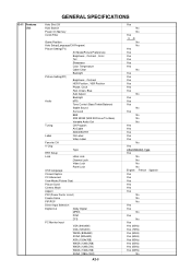
... Red, Green, Blue Auto Adjust Backlight Audio MTS Tone Control (Bass/Treble/Balance) Stable Sound Surround BBE SRS WOW (SRS 3D/Focus/Tru Bass) Variable Audio Out Tuning CH Program Air/Cable ADD/DELETE Label CH Label Video Label Favorite CH V-Chip Type RRT Setup Lock Hotel Lock Channel Lock Video Lock Panel Lock OSD Language Closed Caption CC Advanced View Mode (Picture Size) Picture Scroll Cinema Mode Aspect PFC(Power Factor circuit) Freeze frame PIP/POP Direct Input Selection Digital Out Dolby Digital...
... Red, Green, Blue Auto Adjust Backlight Audio MTS Tone Control (Bass/Treble/Balance) Stable Sound Surround BBE SRS WOW (SRS 3D/Focus/Tru Bass) Variable Audio Out Tuning CH Program Air/Cable ADD/DELETE Label CH Label Video Label Favorite CH V-Chip Type RRT Setup Lock Hotel Lock Channel Lock Video Lock Panel Lock OSD Language Closed Caption CC Advanced View Mode (Picture Size) Picture Scroll Cinema Mode Aspect PFC(Power Factor circuit) Freeze frame PIP/POP Direct Input Selection Digital Out Dolby Digital...
Service Manual
Page 14
... --- Input 2 Video Output Audio Output Component Input 1 Analog Audio Component Input 2 Analog Audio HDMI Input Analog Audio Sub Woofer Out PC Monitor Input Analog Audio Digital Audio Output DC Jack (Center +) VHF/UHF Antenna Input Video Input 3 Audio Input 3 S - W x D x H (mm) w/o Handle, Stand Approx. Input 1 Video Input 2 Audio Input 2 S - G-13 Interface G-14 Set Size G-15 Weight G-16 Carton G-17 Material GENERAL SPECIFICATIONS Switch Indicator Terminals Top Power (Tact) Channel Up/Menu Up Channel Down/Menu Down Volume Up/Menu > Volume Down/Menu < Menu Play...
... --- Input 2 Video Output Audio Output Component Input 1 Analog Audio Component Input 2 Analog Audio HDMI Input Analog Audio Sub Woofer Out PC Monitor Input Analog Audio Digital Audio Output DC Jack (Center +) VHF/UHF Antenna Input Video Input 3 Audio Input 3 S - W x D x H (mm) w/o Handle, Stand Approx. Input 1 Video Input 2 Audio Input 2 S - G-13 Interface G-14 Set Size G-15 Weight G-16 Carton G-17 Material GENERAL SPECIFICATIONS Switch Indicator Terminals Top Power (Tact) Channel Up/Menu Up Channel Down/Menu Down Volume Up/Menu > Volume Down/Menu < Menu Play...
Service Manual
Page 16
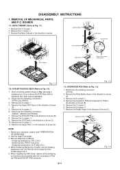
... (B). 5. Remove the 4 screws 3. 9. Use the Lead Free solder. 3. When installing the DVD Deck, remove all the soldering on the short circuit position after the connection of arrow (A). 3. Remove the Plate Button Ass'y in the direction of arrow. 1 222 2 11 2 12 1 2 1 1 1 1 1 1 1 1 1 1 11 1 1 SHIELD MPEG (C) DVD Deck (B) 3 3 Pick Up PCB 3 3 DVD MT PCB 2 2 22 (A) 4 4 Angle DVD-1 Short circuit using a soldering iron. Remove the 6 screws 1. 4. Remove the Operation PCB and Operation 2 PCB...
... (B). 5. Remove the 4 screws 3. 9. Use the Lead Free solder. 3. When installing the DVD Deck, remove all the soldering on the short circuit position after the connection of arrow (A). 3. Remove the Plate Button Ass'y in the direction of arrow. 1 222 2 11 2 12 1 2 1 1 1 1 1 1 1 1 1 1 11 1 1 SHIELD MPEG (C) DVD Deck (B) 3 3 Pick Up PCB 3 3 DVD MT PCB 2 2 22 (A) 4 4 Angle DVD-1 Short circuit using a soldering iron. Remove the 6 screws 1. 4. Remove the Operation PCB and Operation 2 PCB...

Service Manual
Page 18
...;cm (Screw 4, 5) Fig. 2-2-A Check Lock Check Hook Check Lock Fig. 2-1-B 40 ± 5mm Loader Ass'y Check Hook Fig. 2-1-C NOTE 1. Then install it correctly as shown Fig. 2-2-B to align the teeth as shown Fig. 2-2-E. If the repair is needed if the disassembly is correct. 3. Unlock the 2 supports 2. 3. Remove the Gear Motor. Remove the screw 2. 6. Remove the screw 3. 8. Remove the 3 screws 1. 2. Remove the Gear Middle. 5. Minute adjustments are needed except listed parts, replace the DVD MECHA...
...;cm (Screw 4, 5) Fig. 2-2-A Check Lock Check Hook Check Lock Fig. 2-1-B 40 ± 5mm Loader Ass'y Check Hook Fig. 2-1-C NOTE 1. Then install it correctly as shown Fig. 2-2-B to align the teeth as shown Fig. 2-2-E. If the repair is needed if the disassembly is correct. 3. Unlock the 2 supports 2. 3. Remove the Gear Motor. Remove the screw 2. 6. Remove the screw 3. 8. Remove the 3 screws 1. 2. Remove the Gear Middle. 5. Minute adjustments are needed except listed parts, replace the DVD MECHA...
Service Manual
Page 22
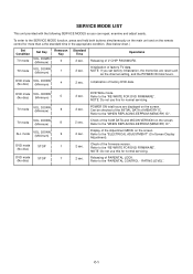
... VERSION on the screen. NOTE: Do not use this for normal servicing. DOWN (No disc) (Minimum) 4 2 sec. DOWN (No disc) (Minimum) 5 TV mode VOL. POWER ON total hours are reset such as the channel setting, and the POWER ON total hours. SERVICE MODE LIST This unit provided with the following SERVICE MODES so you set factory initialization, the memories are displayed on the remote control for normal servicing. Refer to...
... VERSION on the screen. NOTE: Do not use this for normal servicing. DOWN (No disc) (Minimum) 4 2 sec. DOWN (No disc) (Minimum) 5 TV mode VOL. POWER ON total hours are reset such as the channel setting, and the POWER ON total hours. SERVICE MODE LIST This unit provided with the following SERVICE MODES so you set factory initialization, the memories are displayed on the remote control for normal servicing. Refer to...
Service Manual
Page 23
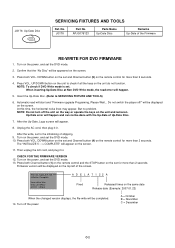
... Non DVD Write mode, the read will appear. 8. Up-Date error will happen. 5. Press both Channel button (1) on the remote control and the STOP button on the power, and set for more than 2 seconds. F/W Ver. ADELA7122A Initialize: Complete Laser drive time DVD LD: 0Hour CD LD : 0Hour A D E L A 7 1 22 A Fixed Released times on the same date Release date (Example: 2007.01.22) When the changed version displays...
... Non DVD Write mode, the read will appear. 8. Up-Date error will happen. 5. Press both Channel button (1) on the remote control and the STOP button on the power, and set for more than 2 seconds. F/W Ver. ADELA7122A Initialize: Complete Laser drive time DVD LD: 0Hour CD LD : 0Hour A D E L A 7 1 22 A Fixed Released times on the same date Release date (Example: 2007.01.22) When the changed version displays...
Service Manual
Page 24
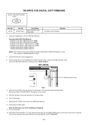
... "update.dat" in CD to normal screen. 6. Set the minus driver to the topside of the Firmware 1. Turn on the power. RE-WRITE FOR DIGITAL SOFT FIRMWARE JG176 USA HD DTV ROM DISC Ref. Insert the USB Flash Memory to USB connector. (Refer to the initializing of WINDOWS2000 is plugged out. 3. Unplug the AC CORD, and remove the USB Flash Memory. 8. After the data input, set and turn on the power...
... "update.dat" in CD to normal screen. 6. Set the minus driver to the topside of the Firmware 1. Turn on the power. RE-WRITE FOR DIGITAL SOFT FIRMWARE JG176 USA HD DTV ROM DISC Ref. Insert the USB Flash Memory to USB connector. (Refer to the initializing of WINDOWS2000 is plugged out. 3. Unplug the AC CORD, and remove the USB Flash Memory. 8. After the data input, set and turn on the power...
Service Manual
Page 25
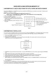
... select DATA. After the data input, set and Channel button (1) on the remote, step through the DATA using UP/DOWN button until all data has been checked. Press both VOL. DOWN button on the set to the TV mode. 2. Turn POWER on the remote control for the new MEMORY IC. ADDRESS and DATA should be checked on the POWER, and set and Channel button (6) on . 10. When satisfied...
... select DATA. After the data input, set and Channel button (1) on the remote, step through the DATA using UP/DOWN button until all data has been checked. Press both VOL. DOWN button on the set to the TV mode. 2. Turn POWER on the remote control for the new MEMORY IC. ADDRESS and DATA should be checked on the POWER, and set and Channel button (6) on . 10. When satisfied...
Service Manual
Page 26
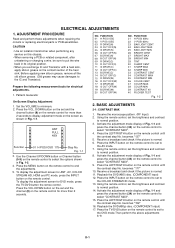
... assemblies. CAUTION • Use an isolation transformer when performing any service on the contact section of Fig. 1-1 and press the channel button (34) on the remote control to minimum. 2. DOWN button on the set to select the options shown in Fig. 1-1. Press the MENU button on the remote control to display adjustment mode on the remote control for ANT, AV, COLOR STREAM HD, HDMI and PC mode, press the INPUT button on the remote control...
... assemblies. CAUTION • Use an isolation transformer when performing any service on the contact section of Fig. 1-1 and press the channel button (34) on the remote control to minimum. 2. DOWN button on the set to select the options shown in Fig. 1-1. Press the MENU button on the remote control to display adjustment mode on the remote control for ANT, AV, COLOR STREAM HD, HDMI and PC mode, press the INPUT button on the remote control...
Service Manual
Page 27
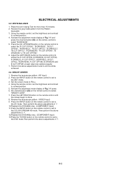
Receive the gray scale pattern from the Pattern Generator. 3. Press the CH. Using the remote control, set the brightness and contrast to normal position. 5. Receive the monoscope pattern. (VIDEO Input) 9. Then perform the above adjustments 2~7. Set the screen mode to set in Aging Test for more than 15 minutes. 2. D-2 ELECTRICAL ADJUSTMENTS 2-2: WHITE BALANCE 1. Activate the adjustment mode display of Fig. 1-1 press 6. the channel button (26) on the remote control until the white achieved. 2-3: BRIGHT CENTER 1. Using the remote control, set the...
Receive the gray scale pattern from the Pattern Generator. 3. Press the CH. Using the remote control, set the brightness and contrast to normal position. 5. Receive the monoscope pattern. (VIDEO Input) 9. Then perform the above adjustments 2~7. Set the screen mode to set in Aging Test for more than 15 minutes. 2. D-2 ELECTRICAL ADJUSTMENTS 2-2: WHITE BALANCE 1. Activate the adjustment mode display of Fig. 1-1 press 6. the channel button (26) on the remote control until the white achieved. 2-3: BRIGHT CENTER 1. Using the remote control, set the...

Service Manual
Page 30
Change F401. Yes Change DIGITAL PCB. Check IC402 and peripheral circuit. Change R412. Check IC401 and peripheral circuit. E-1 Yes No Is there voltage at pin 10 of IC402 6V? TROUBLESHOOTING GUIDE (LCD SECTION) POWER DOES NOT TUNER ON Is F401 broken? Yes Yes Is R412 broken? No No Is there voltage at pin No 1 of IC401 19V?
Change F401. Yes Change DIGITAL PCB. Check IC402 and peripheral circuit. Change R412. Check IC401 and peripheral circuit. E-1 Yes No Is there voltage at pin 10 of IC402 6V? TROUBLESHOOTING GUIDE (LCD SECTION) POWER DOES NOT TUNER ON Is F401 broken? Yes Yes Is R412 broken? No No Is there voltage at pin No 1 of IC401 19V?

Service Manual
Page 34
Yes Check IC701 and peripheral circuit. TROUBLESHOOTING GUIDE THE COLOR DOES NOT APPEAR Is setting of IC701? Yes No Is the color signal received? Change DIGITAL PCB. Check Q701,Q702 and peripheral circuit. No Is there color signal at Yes pins A9 and A13 of IC2401? Yes Is there color signal at No pins 33 and 35 of color No normal? Adjust the color. Receive the color signal. E-5
Yes Check IC701 and peripheral circuit. TROUBLESHOOTING GUIDE THE COLOR DOES NOT APPEAR Is setting of IC701? Yes No Is the color signal received? Change DIGITAL PCB. Check Q701,Q702 and peripheral circuit. No Is there color signal at Yes pins A9 and A13 of IC2401? Yes Is there color signal at No pins 33 and 35 of color No normal? Adjust the color. Receive the color signal. E-5


