
Sharp LC-26AD22U Support Question
Sharp LC-26AD22U Support Question
Find answers below for this question about Sharp LC-26AD22U.Need a Sharp LC-26AD22U manual? We have 1 online manual for this item!
Question posted by Jdcpanet on November 29th, 2014
Connecting Samsung Sound Bar
Tried RCA cables to digital audio input; also tried digital cable to digital audio input. Sound bar does not "find TV" so No Sound. What am I doing wrong?
Current Answers
Answer #1: Posted by TommyKervz on December 18th, 2014 3:56 AM
TommyKervz

Member since:
January 10th, 2013 Points: 17,776,783

Member since:
January 10th, 2013 Points: 17,776,783
Check connections instructions below
Related Sharp LC-26AD22U Manual Pages
Service Manual - Page 1
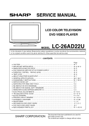
...; SERVICING FIXTURES AND TOOLS C-2 • RE-WRITE FOR DVD FIRMWARE C-2 • RE-WRITE FOR DIGITAL SOFT FIRMWARE C-3 • WHEN REPLACING EEPROM (MEMORY) IC C-4 • ELECTRICAL ADJUSTMENTS D-1~D-5 •... AT NO POWER SUPPLY A1-6 • PARENTAL CONTROL - LCD COLOR TELEVISION/ DVD VIDEO PLAYER
MODEL LC-26AD22U
In the interests of user-safety (Required by safety regulations in some ...
Service Manual - Page 4
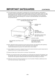
...cable system is closing. Unauthorized substitutions may result in proper operating condition.
22) Keep your fingers clear of antenna discharge unit, connection to grounding electrodes, and requirements for the grounding electrode. Otherwise, sudden high volume sound...
(CONTINUED)
19) If an outside antenna or cable system is connected to the unit, be sure the service technician uses...
Service Manual - Page 5
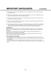
... Moisture will be connected to the grounding system of the building, as close to the point of the player if the player is provided to call the cable TV system installer's attention...sound, it on, or make absolutely sure that the cable ground shall be impaired. HOW TO HANDLE THE LCD PANEL • Do not press hard or jolt the LCD panel. If the liquid gets in the operating section of cable...
Service Manual - Page 6
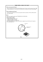
... Deck with no soldering, the Laser may be damaged.
[ When installing the DVD Deck ] Remove all the soldering on the short circuit position after the connection of solder, use the draw in Fig. 1 using a soldering iron.
NOTE • Before your operation, please read "PREPARATION OF SERVICING". • Use the Lead Free...
Service Manual - Page 9
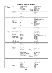
...TV Sound Tuner Sound Muting Video Signal
Fwd
Rev
Analog Digital System Destination CH Coverage
Picture(FP) Sound(FS) FP-FS
Input Level Output Level S/N Ratio (Weighted) Horizontal Resolution at DVD Mode
Actual Actual
RGB Signal Audio Signal
Output Level Input Level Output Level
at DVD at TV... times -US System M ATSC(8VSB)/QAM 1Tuner US (W/CABLE) 2~69, 4A, A-5~A-1, A~I, J~W, W+1~W+84 44.00MHz ...
Service Manual - Page 11
...
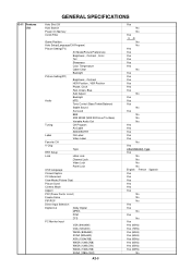
Tone Control (Bass/Treble/Balance)
Stable Sound
Surround
BBE
SRS WOW (SRS 3D/Focus/Tru Bass)
Variable Audio Out
Tuning
CH Program
Air/Cable
ADD/DELETE
Label
CH Label
Video Label
Favorite CH
V-Chip
Type
RRT Setup
Lock
Hotel Lock
Channel Lock
Video Lock
Panel Lock
OSD Language
Closed Caption
CC Advanced
View Mode...
Service Manual - Page 14
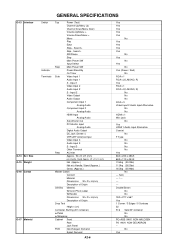
... (40' container)
w/Pallet
w/Wrapping
Cabinet Front
Rear
Jack Panel
PCB
Non-Halogen Demand
Eyelet Demand
A2-6
Yes Yes Yes Yes Yes
No Yes Yes Yes Yes
No Yes
No Yes
No Yes (Green / Red)
No RCA x 1 RCA x 2(L/MONO, R) Yes RCA x 1 RCA x 2(L/MONO, R)
No No No RCA x 3 Video Input 2 Audio Input Alternative No No HDMI x 1 Mini Jack No Yes HDMI...
Service Manual - Page 16
...
PCB 3 22
3
22
2
2
(C)
2
(A)
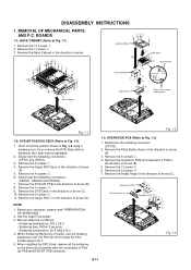
Fig. 1-3
B1-1 Remove the 14 screws 1. 2. When installing the DVD Deck, remove all the soldering on the short circuit position after the connection of solder, use the drawing equipment over the Pick Up Unit to Fig. 1-1)
1. Remove the 6 screws 1. 4. Remove the 2 screws 3. 7. Back Cabinet
(D)
Fig. 1-1
1-2: DVD MT PCB...
Service Manual - Page 31

... Is there signal at pins 1 and 20 of IC1001?
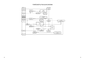
E-2 TROUBLESHOOTING GUIDE
THE PICTURE APPEARS, BUT THE AUDIO DOES NOT APPEARS. (ATRFMODE)
No Is CP1001 connected? No
Yes Is there signal at pin 15 of CP1001? Connect CP1001. Check IC1002 and peripheral circuit.
No
Change TU2801.
Check IC901 and peripheral circuit. Change SP1001.
Yes...
Service Manual - Page 32

... at pins 7, Yes 8, 10, 11, 13, 14, 16, 17, 19 and 20 of CP406
12V? Yes
Connected CD7201.
TROUBLESHOOTING GUIDE
THE PICTURE DOES NOT APPEAR (1)
No Does backlight shine? Yes
Check DIGITAL PCB.
Change V2301(PANEL). Yes
Is there signal at pins
No
1, 2,3, 4and 5 of CD7201?
Change IC2405.
No
No Is there signal...
Service Manual - Page 37

No
Does CD2001 connect Yes with CP2301 correctly? No
Is the voltage between JG017 and JG018 less than 0.6V? No
Connect CD2301.
Yes
Does this display
Yes
"INCORRECT DISC"? Yes
No Does disc rotate?
Change DVD DECK.
Change IC4001.
Yes
Change IC4001.
TROUBLESHOOTING GUIDE
DOES NOT PLAY DVD
Does this display
No
reading mark? Change DVD DECK.
E-8
Service Manual - Page 38

Change DVD DECK. Yes
Change IC4001. E-9
Yes
Does this display
Yes
"INCORRECT DISC"?
Yes
No Does disc rotate? Change DVD DECK. No
Is the voltage between JG019 and JG018 less than 0.6V?
No
Does CD2001 connect Yes with CP2301 correctly? No
Connect CD2301.
Change IC4001.
TROUBLESHOOTING GUIDE
DOES NOT PLAY CD
Does this display
No
reading mark?
Service Manual - Page 42
...23
SW +1.5V
REG+9V IC3404 P.CON +9V BA00BC0WFP
SOUND AMP IC1001
AN17808B
AV SW IC701 AN15853B-E1
Q3410 LCD +B RSQ035P03
PANEL V2301 LK255T3LZ5A
Q3406 P.CON +5V 2SB1132
AD CONVERTER IC6601
...MST3583M-LF-110
SUBɹMICON IC101
OEC6088A
IC3403 BD3504FVM
Q3402 2SB1132
DTV +5V
ATSC/CLEAR CABLE ASIC IC ...
Service Manual - Page 54
...D
E
F
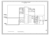
AV OUT SCHEMATIC DIAGRAM
8
(DIGITAL PCB)
G
H
8
7
6
FROM/TO ... B
C2563 0.1 B
C2562 0.1 B
C2561 0.1 B
C2560 0.1 B
ATSC/CLEAR CABLE ASIC IC IC2401 X242 (13/14 VIDEO ENCODER)
2.5 Y4 A1VDD
0 Y3 2.5 AB4...
C2585 10 C
X242_SPDIF W900
P.CON+9V W901
C2586 0.001 B
7
6
5
4
FROM/TO SOUND AUDIO_R_OUT AUDIO_L_OUT
3
C2587 0.001 B
2
NOTE: THIS SCHEMATIC DIAGRAM IS THE LATEST AT THE TIME
...
Service Manual - Page 55

... OUT GND +3.3V +2.5V_IO
3
FROM/TO SDRAM
+2.5V_IO
+3.3V
VDDC_1.0V
MEM[1.8V]
GND
2
PCBDH0 CEF276
1
H
H-24 A
B
C
D
E
F
G
POWER3 SCHEMATIC DIAGRAM
8
(DIGITAL PCB)
REG+9V IC IC3404 BA00BC0WFP
FROM/TO SOUND
SOUND_GND
SOUND+B
AT+5V
7
P.CON+5V
P.CON+9V
+3.3V
GND
V_C V_IN GND V_OUT V_ADJ
1
2
6
4
5
5.0 12.0 0
9.0 4.5
SW+1.5V[DTV]
SW+12V AT+5V...
Service Manual - Page 58

...
(DIGITAL PCB)
G
H
8
7
7
REMOCON_IN C_SYNC
KEY_B KEY_A
AFT
POWER_ON_MUTE_H INVETER_H LCD-H
FROM/TO AV SWITCH/JACK C_SYNC
START_SW DVD_RESET DVD_POWER
FROM/TO ASIC DTV_RESET
6
FROM/TO FLASH
TX_[X242]
RX_[X242]
FROM/TO FRONT END AFT_1 AFT_2 SD-H AFT
FROM/TO POWER3
5
DTV_ON-H LIGHT_CTL
LCD-H INVETER_H
POWER_ON-H POWER_FAIL
P.CON+5V
4
FROM/TO SOUND...
Service Manual - Page 60

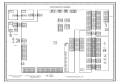
...SOUND SCHEMATIC DIAGRAM
8
(DIGITAL PCB)
G
H
8
7
FROM/TO FRONT END
DVD_A_SW_DVD-H
FROM/TO POWER3 +3.3V
FROM/TO AV SWITCH JACK ZERO_MUTE
FROM/TO POWER3
6
AT+5V
FROM/TO FRONT END AUDIO_MUTE-H
FROM/TO POWER3
GND
SOUND... JACK
SW_A_OUT_R
SW_A_OUT_L
2
R1021 8.2K
R1022 4.7K
R1026 15K
C1038 10 B
C1039 10 B
AUDIO SW IC IC1004 MM1501XNRE
5.3
0
1
6
Vin1 SW
0
4.6
2
5
GND OUT
5.3
...
Service Manual - Page 63

...WAS MEASURED WITH THE DIGITAL TESTER WHEN THE COLOR...C443
47 0.1 B
W828
R456 2.2K +-1%
SOUND+B[SW]
P.CON+5V INV_SW+24V GND SW+12V[UNREG] GND_S SW+5.5V
ERC91-02
1.8 3W
SOUND+B[SW]
D413 1SS355
C419 100P CH D415 ... 47K
0 0.8
0 VCC REGULATOR Q406
KTC3875S_Y_RTK
R427 15K
CAUTION: IS THE LIVE CONNECTION
FEED BACK IC408
PS2561AL1-1-V(W) 2.5
0
FEED BACK IC409
PS2561AL1-1-V(W) 0.8
0
C468 250V0...
Service Manual - Page 64

...DIGITAL TRANSISTOR G
H 8
7
6
5
4
3
2
PCB240 CEF273
1 H
H-42 ATTENTION :POUR UNE PROTECTION CONTINUE LES RISQUES D'INCEIE N'UTILISER QUE DES FUSIBLE DE MEME TYPE 1.6A 125V(F404).
A
B
H-41
CAUTION: IS THE LIVE CONNECTION... 0
R499
100 R483
6.8K +-1%
R484 47 +-1%
SOUND+B[SW] GND_S
GND
CP411(CP3401) TWG-P23P-B1
SOUND+B 1
SOUND+B 2
SOUND GND 3
SOUND GND 4
GND
5
GND
6
GND
7
R493 2.2K...
Service Manual - Page 67
...
TO LCD PANEL CD7201_1
LCD PANEL V2301
D
...TO CHANGE WITHOUT NOTICE
E
F
G
H
8
CP3401
SOUND+B 1
SOUND+B 2
SOUND GND 3
SOUND GND 4
GND
5
GND
6
GND
7
SW+12V ...
D1-
5
D1-S
4
D1+
3
D2-
2
D2-S
1
D2+
HDMI AUDIO IN J4201 1
R3 L2
2
GND
N C
N C
GND
LCD_SH/QD CP2407
...VDD
6
DIGITAL PCB PCBDH0 CEF276
GND
GND
NC
GND
20 RXIN0-
19 RXIN0+
GND
RXIN1- RXIN1+
GND
RXIN2-
Similar Questions


Flat Panel Lc20b4u-sm Is Broken.
Can I replace a broke flat panel lc 20b4u-sm
Can I replace a broke flat panel lc 20b4u-sm
(Posted by Mbermudezford 11 years ago)

Problem Connecting Surround Sound To My Brand New Sharp Lc-70le640u
I can not get any response from my surround sound unit. I have audio thru the tv speakers and I hav...
I can not get any response from my surround sound unit. I have audio thru the tv speakers and I hav...
(Posted by dijom 11 years ago)

Can I Connect/access The Internet In My Sharp Lc 52d62u Tv
(Posted by lotofcash 12 years ago)

Where Can I Purchase A Lcd Screen For My Lc-46sb54u Flat Panel Tv Brand Is Shar
(Posted by allwayswillbe 12 years ago)